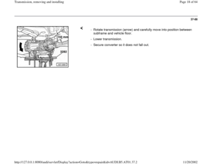
Page 9 of 64
37-79
For 6 cylinder engines except for 2.7 Liter 5V
turbo engine:
- Unclip vent hose for alternator -1-.
- Unbolt bracket for ATF line -2- at oil pan.
- Separate ATF lines -1- to ATF cooler.
- Plug ATF lines with clean plug.
- Unbolt bracket for ATF line -3-.
- Remove transmission side starter bolt -2-.
Pa
ge 9 of 64 Transmission, removin
g and installin
g
11/20/2002 htt
p://127.0.0.1:8080/audi/servlet/Dis
play?action=Goto&t
yp
e=re
pair&id=AUDI.B5.AT01.37.2
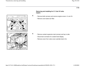
Page 10 of 64
37-80
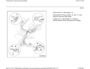
Vehicles with 4 cylinder engine
- Remove bolt -12- to separate bracket for ATF
line -11- from engine.
- Remove bolt -1-.
- Pull off lines -2- and -3- from transmission.
- Plug lines and openings at transmission with
clean plugs.
- Lay lines aside so they are not damaged.
Pa
ge 10 of 64 Transmission, removin
g and installin
g
11/20/2002 htt
p://127.0.0.1:8080/audi/servlet/Dis
play?action=Goto&t
yp
e=re
pair&id=AUDI.B5.AT01.37.2
Page 11 of 64
37-81
All except 2.7 Liter 5V turbo engine:
- Remove starter.
Repair Manual, Electrical Equipment, Repair
Group 27; Starter, removing and installing
Disconnect torque converter from drive plate
For vehicles with hex bolts:
For vehicles with Torx bolts: - Remove torque converter from drive plate by removing 3 bolts using
special tool V175 (turn crank shaft an additional 1/3 turn every time).
- Unbolt 3 torque converter bolts from drive plate using respective Torx
insert (turn crank shaft an additional 1/3 turn every time).
Pa
ge 11 of 64 Transmission, removin
g and installin
g
11/20/2002 htt
p://127.0.0.1:8080/audi/servlet/Dis
play?action=Goto&t
yp
e=re
pair&id=AUDI.B5.AT01.37.2
Page 12 of 64
37-82
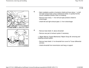
All-wheel-drive vehicles
Repair Manual, Engine Mechanical, Repair Group 26; removing and
installing exhaust system. - Remove heat shield -A- above driveshaft.
- Remove rear part of exhaust system if necessary:- Remove heat shield -2- for driveshaft from cover for Torsen differential
(arrows).
- Unbolt driveshaft from transmission and hang or support.
Pa
ge 12 of 64 Transmission, removin
g and installin
g
11/20/2002 htt
p://127.0.0.1:8080/audi/servlet/Dis
play?action=Goto&t
yp
e=re
pair&id=AUDI.B5.AT01.37.2
Page 13 of 64
37-83
Continuation for all vehicles
Use 3282/19 adjustment plate to position the 3282 transmission support
for Automatic Transmission 01V.
The symbols on the adjustment plate indicate the necessary mounts and
the arrow points toward front of vehicle. - Position 3282 transmission support.
Automatic Transmission 01V with All Wheel Drive is supported at the
same positions as the Front Wheel Drive version. - Roll VAG1383A engine/transmission hoist with 3282 transmission
support under transmission and support transmission.
- Align adjustment plate parallel to transmission.
- Secure transmission on 3282 transmission support using bolt -A-.
- Remove left and right transmission support with transmission mount
page 37
-125
Pa
ge 13 of 64 Transmission, removin
g and installin
g
11/20/2002 htt
p://127.0.0.1:8080/audi/servlet/Dis
play?action=Goto&t
yp
e=re
pair&id=AUDI.B5.AT01.37.2
Page 14 of 64
37-84
- Unbolt multi-function Transmission Range (TR) switch -F125- for
protection against damage (arrows) and expose wiring harness.
- Mark position of mounting bracket for selector lever cable to
transmission housing for re-installation, unbolt mounting bracket
(arrows).
Pa
ge 14 of 64 Transmission, removin
g and installin
g
11/20/2002 htt
p://127.0.0.1:8080/audi/servlet/Dis
play?action=Goto&t
yp
e=re
pair&id=AUDI.B5.AT01.37.2
Page 15 of 64
37-85
- If installed, press off securing brace (arrow) at end of selector lever
cable.
- Pry off selector lever cable from lever/shift rod (arrow).
- Remove upper connecting bolts for engine/transmission.
Pa
ge 15 of 64 Transmission, removin
g and installin
g
11/20/2002 htt
p://127.0.0.1:8080/audi/servlet/Dis
play?action=Goto&t
yp
e=re
pair&id=AUDI.B5.AT01.37.2
Page 16 of 64
37-86
For 6 cylinder TDI engines
Note:
Illustration depicts engine from rear with the transmission removed.
Continuation for all vehicles - Loosen bolt -A- (at rear of turbocharger) several turns and rotate brace
-B- to side in arrow direction. Then re-tighten bolt -A- lightly.
If this is not the case, an axle alignment must be performed after the
carrier is installed. - Before loosening subframe, it must be checked whether holes -1- and -
2- (at least) line up using 3393 testing mandrel.
Pa
ge 16 of 64 Transmission, removin
g and installin
g
11/20/2002 htt
p://127.0.0.1:8080/audi/servlet/Dis
play?action=Goto&t
yp
e=re
pair&id=AUDI.B5.AT01.37.2


 switch -F125- for
protection against damage (arrows) and expose wiring harness.
- Mark position of mounting bracket for selector l")
 at end of selector lever
cable.
- Pry off selector lever cable from lever/shift rod (arrow).
- Remove upper connecting bolts for")
")