Page 49 of 79
01-94
Function test: Traction control button; set measurement range on VAG1526: 20 V =
Test
step VAG
1598/20
sockets Test of
Test requirements
- Additional work stepsSpecified value
Corrective action
22 - Function of
traction control
button Ignition switched off Function of traction control
indicator light -K86- was
already checked in step 21. Multi-pin connector connected
to ABS control module -J104-
and retainer catch engaged.
- Switch on ignition
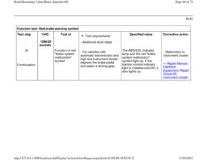
- Press traction control buttonTraction control
indicator light -
K86- lights up - Switch off ignition.
- Detach multi-pin
connector from ABS control
module -J104- and remove.
- Press traction control button
again Traction control
indicator light -
K86- goes out. - Connect VAG1598/20 test
box.
Test step 22: Continued on next page.
Pa
ge 49 of 79 Read Measurin
g Value Block
(function 08
)
11/20/2002 htt
p://127.0.0.1:8080/audi/servlet/Dis
play?action=Goto&t
yp
e=re
pair&id=AUDI.B5.SU02.01.8
Page 50 of 79
01-95
Function test: Traction control button; set measurement range on VAG1526: 20 V =
Test step
VAG
1598/20
sockets Test of
Test requirements
- Additional work
steps Specified
value Corrective action
22 28 + 44 Function of
traction control
button Ignition switched
on.
Continuation:
- Traction control
button not pressed 0.0 to 0.5
V
- Traction control
button pressed 10.0 to 14.5
V
Electrical Wiring Diagrams,
Troubleshooting & Component
Locations - Check wire from terminal 28 to
Ground (GND).
- Check wire from terminal 44 to
traction control button, terminal 6.
- Check voltage supply from terminal 5
of traction control button to terminal 15.
- If no malfunctions can be found using
the procedures in these steps, replace
the traction control button.
Pa
ge 50 of 79 Read Measurin
g Value Block
(function 08
)
11/20/2002 htt
p://127.0.0.1:8080/audi/servlet/Dis
play?action=Goto&t
yp
e=re
pair&id=AUDI.B5.SU02.01.8
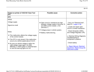
Page 51 of 79
01-96
Voltage measurement; set measurement range on VAG1526: 20 V =
Test
step VAG
1598/20
sockets Test of
Test
requirements
- Additional work
steps Specified
value Corrective action
23 1 + 28
1 + 29 Voltage supply to ABS
control module -J104- via
terminal 15 Ignition
switched on. 10.5 to 14.5
V
Electrical Wiring Diagrams,
Troubleshooting & Component
Locations - Check wiring from terminals 28
and 29 to Ground (GND).
- Check wire from terminal 1 to
terminal 15.
Pa
ge 51 of 79 Read Measurin
g Value Block
(function 08
)
11/20/2002 htt
p://127.0.0.1:8080/audi/servlet/Dis
play?action=Goto&t
yp
e=re
pair&id=AUDI.B5.SU02.01.8
Page 52 of 79
 table
Notes:
Connect the VAG1551 Scan Tool (ST) and select address word 03 \"Brake Electronics\".
Check the control module version page 01
-52
and press th")
01-97
Diagnostic Trouble Code (DTC) table
Notes:
Connect the VAG1551 Scan Tool (ST) and select address word 03 "Brake Electronics".
Check the control module version page 01
-52
and press the button.
Press buttons -0- and -2- to select "Check DTC Memory" function 02. Press -Q- button to confirm input.
Notes:
Each malfunction is assigned a 5-digit Diagnostic Trouble Code (DTC). The DTC is located in the left column of the DTC
table. If you have switched the printer on by pressing the "PRINT" button, the VAG1551 scan tool (ST) prints the message
identifying the malfunction and the DTC. Otherwise, DTCs are not displayed by the VAG1551 scan tool.
The contents of DTC memory remain stored until memory is erased, page 01
-15
.
Sporadically occurring malfunctions are identified via indication of "/SP" on the right-hand side of the display.
Static malfunctions that cannot be detected when the vehicle is stationary are also identified with "/SP" if the ignition has
been switched off and then on again.
The following DTC table includes all the DTCs that can be stored by the ABS control module -J104- and displayed and
printed out by the VAS5051 tester or VAG1551 scan tool. Malfunctions are listed by DTC number.
Pa
ge 52 of 79 Read Measurin
g Value Block
(function 08
)
11/20/2002 htt
p://127.0.0.1:8080/audi/servlet/Dis
play?action=Goto&t
yp
e=re
pair&id=AUDI.B5.SU02.01.8
Page 53 of 79
 table Output on printer of VAG1551
Scan Tool (ST) Possible cause
Corrective action
DTC
00000
No malfunction recognized!
If this display appe")
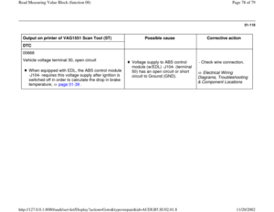
01-98
Diagnostic Trouble Code (DTC) table Output on printer of VAG1551
Scan Tool (ST) Possible cause
Corrective action
DTC
00000
No malfunction recognized!
If this display appears, process
is concluded. No DTCs are
stored in DTC memory.
If corresponding warning lamps
light up anyway, check the
following points:
Voltage supply for ABS control module -J104-
below 10.5 volts at a vehicle speed less than 6
km/h. Open circuit in activation wire for ABS warning
light -K47- between ABS control module (w/EDL) -
J104- and instrument cluster combination
processor -J218-. - See section "Overview of
indicator lamp functions"
If no malfunction can be found, and there is still a
problem, there may be a mechanical malfunction (e.g.
solenoid valve sticking). - Expand troubleshooting to
include "Electrical test", function
test page 01
-68
.
Pa
ge 53 of 79 Read Measurin
g Value Block
(function 08
)
11/20/2002 htt
p://127.0.0.1:8080/audi/servlet/Dis
play?action=Goto&t
yp
e=re
pair&id=AUDI.B5.SU02.01.8
Page 54 of 79
 Possible cause
Corrective action
DTC
00257
Left front ABS inlet
valve -N101-
Open circuit, short circuit to B+ or Ground (")
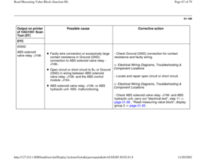
01-99
Output on printer of
VAG1551 Scan Tool
(ST) Possible cause
Corrective action
DTC
00257
Left front ABS inlet
valve -N101-
Open circuit, short circuit to B+ or Ground (GND)
in wiring between ABS hydraulic unit -N55- and
ABS control module -J104-.
Left front ABS inlet valve -N101- malfunctioning - Carry out "electrical test", steps 1 + 13
page 01
-68
.
- If the electrical test does not reveal any
malfunctions, check all wiring and
connectors for loose contacts.
- If no problems are found after
implementing the specified steps, replace
the control module.
00259
Right front ABS inlet
valve -N99-
Open circuit, short circuit to B+ or Ground (GND)
in wiring between ABS hydraulic unit and ABS
control module -J104-.
Right front ABS inlet valve -N99- malfunctioning. - Carry out "electrical test", steps 2 +14
page 01
-68
.
- If the electrical test does not reveal any
malfunctions, check all wiring and
connectors for loose contacts.
- If no problems are found after
implementing the specified steps, replace
the control module.
Pa
ge 54 of 79 Read Measurin
g Value Block
(function 08
)
11/20/2002 htt
p://127.0.0.1:8080/audi/servlet/Dis
play?action=Goto&t
yp
e=re
pair&id=AUDI.B5.SU02.01.8
Page 55 of 79
 Possible cause
Corrective action
DTC
00265
Left front ABS outlet
valve -N102-
Open circuit, short circuit to B+ or Ground")
01-100
Output on printer of
VAG1551 Scan Tool
(ST) Possible cause
Corrective action
DTC
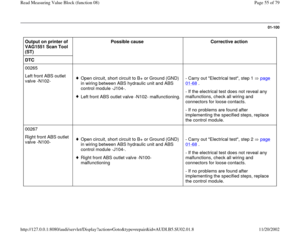
00265
Left front ABS outlet
valve -N102-
Open circuit, short circuit to B+ or Ground (GND)
in wiring between ABS hydraulic unit and ABS
control module -J104-.
Left front ABS outlet valve -N102- malfunctioning. - Carry out "Electrical test", step 1 page
01
-68
.
- If the electrical test does not reveal any
malfunctions, check all wiring and
connectors for loose contacts.
- If no problems are found after
implementing the specified steps, replace
the control module.
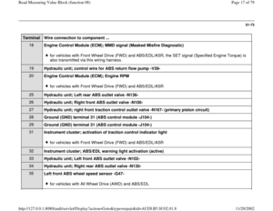
00267
Right front ABS outlet
valve -N100-
Open circuit, short circuit to B+ or Ground (GND)
in wiring between ABS hydraulic unit and ABS
control module -J104-.
Right front ABS outlet valve -N100-
malfunctioning - Carry out "Electrical test", step 2 page
01
-68
.
- If the electrical test does not reveal any
malfunctions, check all wiring and
connectors for loose contacts.
- If no problems are found after
implementing the specified steps, replace
the control module.
Pa
ge 55 of 79 Read Measurin
g Value Block
(function 08
)
11/20/2002 htt
p://127.0.0.1:8080/audi/servlet/Dis
play?action=Goto&t
yp
e=re
pair&id=AUDI.B5.SU02.01.8
Page 56 of 79
 Possible cause
Corrective action
DTC
00273
Right rear ABS inlet
valve -N133-
Open circuit, short circuit to B+ or Ground")
01-101
Output on printer of
VAG1551 Scan Tool
(ST) Possible cause
Corrective action
DTC
00273
Right rear ABS inlet
valve -N133-
Open circuit, short circuit to B+ or Ground (GND)
in wiring between ABS hydraulic unit and ABS
control module -J104-.
Right rear ABS inlet valve -N133- malfunctioning - Carry out "electrical test", steps 4 +16
page 01
-68
.
- If the electrical test does not reveal any
malfunctions, check all wiring and
connectors for loose contacts.
- If no problems are found after
implementing the specified steps, replace
the control module.
00274
Left rear ABS inlet
valve -N134-
Open circuit, short circuit to B+ or Ground (GND)
in wiring between ABS hydraulic unit and ABS
control module -J104-.
Left rear ABS inlet valve -N134- malfunctioning - Carry out "electrical test", steps 3 +15
page 01
-68
.
- If the electrical test does not reveal any
malfunctions, check all wiring and
connectors for loose contacts.
- If no problems are found after
implementing the specified steps, replace
the control module.
Pa
ge 56 of 79 Read Measurin
g Value Block
(function 08
)
11/20/2002 htt
p://127.0.0.1:8080/audi/servlet/Dis
play?action=Goto&t
yp
e=re
pair&id=AUDI.B5.SU02.01.8