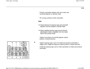
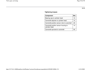
Page 49 of 58
15-83
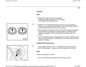
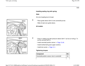
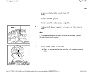
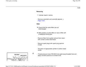
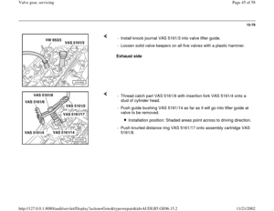
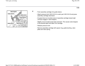
Installing
Note:
A plastic sleeve -A- is enclosed with new valve
shaft seals.
- To prevent damage to new valve stem seals -B-, place plastic sleeve -
A- on valve stem.
- Lightly oil sealing lip of valve stem seal.
- Push valve stem seal onto plastic sleeve.
- Carefully press valve stem seal onto valve guide using presser tool
3365.
- Remove plastic sleeve again.
Note:
The large diameter of the valve keepers points upward. - If valve keepers were taken out of assembly cartridge they must first be
inserted into tool VAS 5161/18.
Pa
ge 49 of 58 Valve
gear, servicin
g
11/21/2002 htt
p://127.0.0.1:8080/audi/servlet/Dis
play?action=Goto&t
yp
e=re
pair&id=AUDI.B5.GE06.15.2
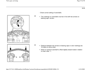
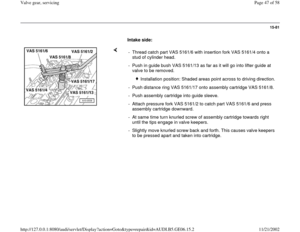
Page 50 of 58
15-84
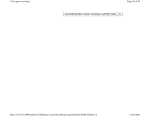
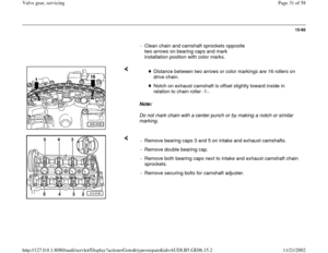
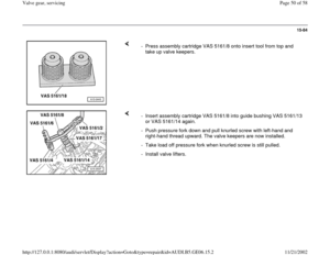
- Press assembly cartridge VAS 5161/8 onto insert tool from top and
take up valve keepers.
- Insert assembly cartridge VAS 5161/8 into guide bushing VAS 5161/13
or VAS 5161/14 again.
- Push pressure fork down and pull knurled screw with left-hand and
right-hand thread upward. The valve keepers are now installed.
- Take load off pressure fork when knurled screw is still pulled.
- Install valve lifters.
Pa
ge 50 of 58 Valve
gear, servicin
g
11/21/2002 htt
p://127.0.0.1:8080/audi/servlet/Dis
play?action=Goto&t
yp
e=re
pair&id=AUDI.B5.GE06.15.2
Page 51 of 58
15-85
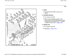
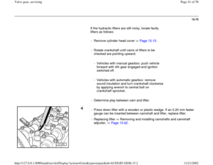
- Install camshafts and camshaft adjuster Page
15
-67
Note:
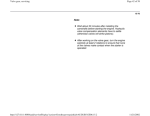
Wait about 30 minutes after installing the
camshafts before starting the engine. Hydraulic
valve compensation elements have to settle
(otherwise valves will strike pistons).
After working on the valve gear, turn the engine
carefully at least 2 rotations to ensure that none
of the valves make contact when the starter is
operated.
Pa
ge 51 of 58 Valve
gear, servicin
g
11/21/2002 htt
p://127.0.0.1:8080/audi/servlet/Dis
play?action=Goto&t
yp
e=re
pair&id=AUDI.B5.GE06.15.2
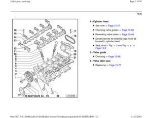
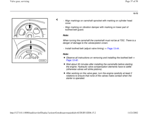
Page 52 of 58
15-86
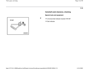
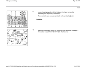
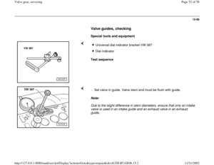
Valve guides, checking
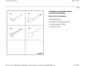
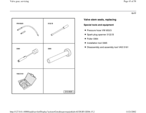
Special tools and equipment
Test sequence
Universal dial indicator bracket VW 387Dial indicator
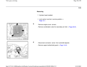
Note:
Due to the slight difference in stem diameters, ensure that only an intake
valve is used in an intake guide and an exhaust valve in an exhaust
guide. - Set valve in guide. Valve stem end must be flush with guide.
Pa
ge 52 of 58 Valve
gear, servicin
g
11/21/2002 htt
p://127.0.0.1:8080/audi/servlet/Dis
play?action=Goto&t
yp
e=re
pair&id=AUDI.B5.GE06.15.2
Page 53 of 58
15-87
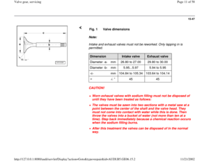
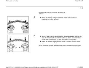
- Determine lateral play.
Wear limit
Intake valve guide
Exhaust valve guide
0.80 mm 0.80 mm
Note:
If the wear limit is exceeded, repeat the
measurement with new valves. Replace valve
guide if wear limit is still exceeded.
If the valve is to be replaced as part of a repair,
use a new valve for the calculation.
Pa
ge 53 of 58 Valve
gear, servicin
g
11/21/2002 htt
p://127.0.0.1:8080/audi/servlet/Dis
play?action=Goto&t
yp
e=re
pair&id=AUDI.B5.GE06.15.2
Page 54 of 58
15-88
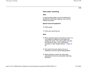
Valve seats, reworking
Note:
If a good seating pattern cannot be obtained by
grinding the valve seats (lapping), they must be
refaced (reworked):
Special tools and equipment
Depth gauge
Valve seat machining tool
Note:
When repairing engines with leaking valves, it is
not sufficient to reface the valve seats and
replace the valves. The valve guides must also
be checked for wear. This is particularly
important on high mileage engines Page 15
-
86
.
Only rework the valve seats as far as is
necessary to ensure a good seating pattern.
Before starting to rework the valve seats,
calculate the maximum permissible reworking
dimension.
Pa
ge 54 of 58 Valve
gear, servicin
g
11/21/2002 htt
p://127.0.0.1:8080/audi/servlet/Dis
play?action=Goto&t
yp
e=re
pair&id=AUDI.B5.GE06.15.2
Page 55 of 58
If the maximum reworking dimension is
exceeded, the hydraulic lifters will not work
properly and the cylinder head will have to be
replaced.
Pa
ge 55 of 58 Valve
gear, servicin
g
11/21/2002 htt
p://127.0.0.1:8080/audi/servlet/Dis
play?action=Goto&t
yp
e=re
pair&id=AUDI.B5.GE06.15.2
Page 56 of 58
15-89
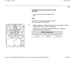
Calculating maximum permissible reworking
dimension
- Insert valve and press firmly against valve
seat.
Note:
If the valve is to be replaced as part of a repair,
use a new valve for the calculation.
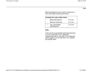
- Measure distance -a- between valve stem end (upper edge) and upper
cylinder head surface -1- with a depth gauge.
- Calculate max. permissible reworking dimension from measured
distance and minimum dimension.
Minimum dimensions
Outer intake valves Central intake valve Exhaust valves
31.0 mm 32.2 mm 31.9 mm
Pa
ge 56 of 58 Valve
gear, servicin
g
11/21/2002 htt
p://127.0.0.1:8080/audi/servlet/Dis
play?action=Goto&t
yp
e=re
pair&id=AUDI.B5.GE06.15.2


, they must be
refaced (reworked):
Special tools and")

