Page 57 of 90
 connection to
one side of the fu")
24-48
Checking for leaks
- Bridge sockets 1 and 65 on the test box using
test leads from VAG1594 A connector test kit.
(This creates an Ground (GND) connection to
one side of the fuel pump relay coil.)
Note:
Once the socket are bridged the fuel pump runs
continuously, even if the engine is not running.
This is because the fuel pump relay receives its
positive voltage supply via the central electrics.
The negative voltage supply for the fuel pump
relay comes via the cable bridge on the test box.
WARNING!
Fire hazard. DO NOT smoke or work near
heaters or have anything in the area that can
ignite fuel!
- Check injectors fuel for leaks (visual check).
When fuel pump is running, only 1 or 2 drops
should escape per minute from each injector.
- If fuel loss is greater, switch off fuel pump
(remove bridge) and replace faulty injector
Page 24
-53
, also observe notes on Page 24
-
53
.
Pa
ge 57 of 90 Motronic Multi
port Fuel In
jection
(MFI
) system, servicin
g
11/22/2002 htt
p://127.0.0.1:8080/audi/servlet/Dis
play?action=Goto&t
yp
e=re
pair&id=AUDI.B5.FU04.24.1
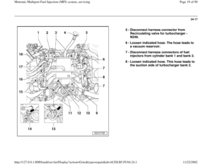
Page 58 of 90
Checking injection quantity
- Place fuel injector which is to be tested into measuring glass from
injection quantity tester VAG1602.
Pa
ge 58 of 90 Motronic Multi
port Fuel In
jection
(MFI
) system, servicin
g
11/22/2002 htt
p://127.0.0.1:8080/audi/servlet/Dis
play?action=Goto&t
yp
e=re
pair&id=AUDI.B5.FU04.24.1
Page 59 of 90
24-49
WARNING!
Make sure test box is inside of passenger compartment.
The fuel pump should run. - Connect one fuel injector terminal to engine Ground (GND) using test
cable and crocodile clamp from VAG1594 connector test kit.
- Connect second fuel injector terminal to B+ using remote control
VAG1348/3 A, adapter cable VAG1348/3-2 and auxiliary cable.
- Bridge sockets 1 and 65 on the test box using test leads from
VAG1594 A connector test kit. (This creates an Ground (GND)
connection to one side of the fuel pump relay coil.)
Pa
ge 59 of 90 Motronic Multi
port Fuel In
jection
(MFI
) system, servicin
g
11/22/2002 htt
p://127.0.0.1:8080/audi/servlet/Dis
play?action=Goto&t
yp
e=re
pair&id=AUDI.B5.FU04.24.1
Page 60 of 90
24-50
- Activate remote control VAG1348/3 A for 30
seconds.
- When all three fuel injectors from the first bank
of cylinders have been activated, place the three
measuring glasses on a level surface.
Specified value for each fuel injector: 135 ... 165
ml
- If measured value for one or more of fuel
injectors is outside tolerance range, switch off
fuel pump (switch ignition off) and replace faulty
fuel injector Page 24
-53
, also observe notes
on Page 24
-53
.
Pa
ge 60 of 90 Motronic Multi
port Fuel In
jection
(MFI
) system, servicin
g
11/22/2002 htt
p://127.0.0.1:8080/audi/servlet/Dis
play?action=Goto&t
yp
e=re
pair&id=AUDI.B5.FU04.24.1
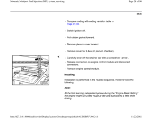
Page 61 of 90
24-51
- Repeat test for fuel injectors from second bank
of cylinders.
- If measured values for all fuel injectors are
outside tolerance range (specification), check
fuel pressure Page 24
-33
.
Note:
When checking the injection quantity, also check
the spray pattern. The spray pattern should be
the same for all the injectors.
Installation of the fuel rail together with injectors
is performed in the reverse sequence. The
following points should be noted when installing:
Replace O-rings at all opened connections.
(When replacing the front O-ring, make sure
not to remove the plastic cap from the
injector head. The O-ring must be pulled off
over the plastic cap.)
Moisten O-rings with clean engine oil.
Pa
ge 61 of 90 Motronic Multi
port Fuel In
jection
(MFI
) system, servicin
g
11/22/2002 htt
p://127.0.0.1:8080/audi/servlet/Dis
play?action=Goto&t
yp
e=re
pair&id=AUDI.B5.FU04.24.1
Page 62 of 90
24-52
Make sure fuel injectors are correctly
positioned, insert vertically into fuel rail and
secure with retainer clips.
Position fuel rail together with injectors
(properly secured) against intake manifold
and press into place evenly all round.
Replace hose clamps and make sure that
they are securely installed.
Pa
ge 62 of 90 Motronic Multi
port Fuel In
jection
(MFI
) system, servicin
g
11/22/2002 htt
p://127.0.0.1:8080/audi/servlet/Dis
play?action=Goto&t
yp
e=re
pair&id=AUDI.B5.FU04.24.1
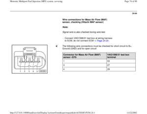
Page 63 of 90
24-53
Fuel rail with fuel injectors, dismantling
and assembling
1 -
Fuel rail
2 -
To intake manifold
3 -
Retaining clip
4 -
O ring
Replace
5 -
Fuel pressure regulator
6 -
O ring Replace
7 -
Injector (N30...N32, N33...N84)
8 -
Retaining clip Must be seated correctly at fuel injector
and fuel rail
Pa
ge 63 of 90 Motronic Multi
port Fuel In
jection
(MFI
) system, servicin
g
11/22/2002 htt
p://127.0.0.1:8080/audi/servlet/Dis
play?action=Goto&t
yp
e=re
pair&id=AUDI.B5.FU04.24.1
Page 64 of 90
24-54
Fuel Pump (FP) relay -J17 and relay
activation, checking
Note:
The fuel pump relay is located in the central electrics in the left-hand
footwell, relay position 4.
A - Checking Fuel Pump (FP) relay -J17
- Remove storage bin in front left-hand footwell.
Electrical Wiring Diagrams, Troubleshooting & Component Locations
The fuel pump relay should pick up (can be felt and heard) and the diode
test lamp should light up. - Remove fuel pump fuse from fuse holder and connect diode test lamp
VAG1527 between Ground and one of the two contacts for the fuel
pump fuse. - Operate starter briefly.
- If fuel pump relay does not pick up, check activation Page 24
-56
.
Pa
ge 64 of 90 Motronic Multi
port Fuel In
jection
(MFI
) system, servicin
g
11/22/2002 htt
p://127.0.0.1:8080/audi/servlet/Dis
play?action=Goto&t
yp
e=re
pair&id=AUDI.B5.FU04.24.1


 using test
cable and crocodile c")

, check
fuel pressure")
")

 relay -J17 and relay
activation, checking
Note:
The fuel pump relay is located in the central electrics in the left-hand
footwell, relay position 4.
A - C")