1998 ACURA INTEGRA anti lock
[x] Cancel search: anti lockPage 35 of 1680

Lubrication Points
No. LUBRICAnON POINTSLUBRICANT
1 E^g,neAPI Service Grade: Use SJ "Energy Conserving" orSH "Energy Conserving ll" grade oil,The oil container may also display the API Certificationmark shown below. Make sure it savs "For GasolineEngines. "
SAE Viscositv: See chart below.
2TransmissionManualHonda Genuine MTF*1
AutomaticGenuine Honda Premium Formula AutomaticTransmission Fluid (ATF)*,
Brake line (lncludes Anti-lock brake line)Genuine Honda DOT3 Brake Fluid13
Clutch lineGenuine Honda DOT3 Brake Fluid*3
Power steering gearboxSteering grease P/N 08733 - 8070E
Release fork lManual transmission)Sup€r High Temp Urea Grease (P/N 08798 - 9002)
1
8
Throttle wire end (Dashboard lower oanel hole)Cruise control actuator wire end(Dashboard lower Danel hole)Silicone grease
o
10
11
14
Throttle cable end (Throttle link)Cruise control actuator cable end (Actuator link)Brake master cvlinder oushrodClutch master cylinder pushrod
Battery terminals
Fuel fill lid
Multi-purpose grease
to
17
18
Engin6 hood hinges and engine hood latchHatch hinges 8od latch or trunk hinges and latchDoor hjnges, upper and lowerDoor ooen detent
Honda White Lithium Grease
19Rear b.ake calipersSilicone grease
20Power steering systemGenuine Honda Power Steering Fluid-V or S*.
21Ai|' conditioning compressorRefrigerant oii ND-O|L8 {P/N38897 - PR7 - A01AH or38899-PR7-A01)(For Refrigerant: HFC-134a (R- 134a))
API SERVICE LABELAPI CERTIFICATION SEAL
Recommended engine oilEngin€ oil viscosity lorambrent lemperature ranges
r(For the details of lubrication points and type of lubricants to be applied, refer to the illustrated index and various work Dro-cedure (such as Assembly/Reassembly, Replacement, Overhaul, Installation. etc.) contained in each section,
*1: Always use Genuine Honda Manual Transmission Fluid (MTF). Using motor oil can cause stiffer shifting because itdoes not contain the proper addtuves.*2: Always use Genuine Honda Premium Formula Automatic Transmission Fluid (ATF). Using a non-Honda ATF can affectshift quality.*3: Always use Genuine Honda DOT 3 B.ake Fluid, Using a non-Honda brake fluid can cause corrosion and decrease thelife of the system.'4: Always use Genuine Honda Power Steering Fluid-V or S. Using any other type of power steering fluid or automatictransmission fluid can cause increase v,/ear and poor steering in cold weather.
L(
{
4-2
Page 199 of 1680

Radiator
Engine Coolant Refilling and Bleeding
CAUTION: When pouring engine coolant, be sure to shut
th6 relay box lid and not to l€t coolant spill on th6 el€c-
trical parts or the paint. lf any coolant spills, rinse it off
immediately.
1. Slide the heater temDerature control lever to maxi-
mum heat.
Make sure the engine and radiator are cool to the
touch.
2. Remove the radiator cap.
3. Loosen the drain plug, and drain the coolant.
4. Remove the drain bolt from the cvlinder block.
ji
Ii'
l:ll
ENGINE DRAIN EOLT78 N.m {8.0 kgt'm,54 lbt.ft)Apply liquid gasket tobolt thread when installing.WASHERReplace.
10-6
5. Apply liquid gasket to the drain bolt threads, then
reinstall the bolt with a new washer and tighten it
securely.
6. Tighten the radiator drain plug securely.
7. Remove, drain and reinstall the reservoir. Fillthe tank
halfway to the MAX mark with water, then up to
MAX mark with antifreeze.
COOLANTRESERVOIR
I
I
I
Page 466 of 1680
![ACURA INTEGRA 1998 Service Repair Manual Troubleshooting Procedures
Checking the Diagnostic Trouble Code (DTC)
with an OBD ll Scan Tool or th€ Honda PGM Tester
When the TCM senses an abnormality in the input or output systems, the lD,] ind](/manual-img/32/56983/w960_56983-465.png "ACURA INTEGRA 1998 Service Repair Manual Troubleshooting Procedures
Checking the Diagnostic Trouble Code (DTC)
with an OBD ll Scan Tool or th€ Honda PGM Tester
When the TCM senses an abnormality in the input or output systems, the lD,] ind")
Troubleshooting Procedures
Checking the Diagnostic Trouble Code (DTC)
with an OBD ll Scan Tool or th€ Honda PGM Tester
When the TCM senses an abnormality in the input or output systems, the lD,] indicator light in the gauge assembly will
blink. When the 16p Data Link Connector (DLC) (located under the dash on the passenger side) is connected to the OBD ll
Scan Tool or Honda PGM Taster as shown, the scan tool or tester will indicate the Diagnostic Trouble Code (DTC) when
the ignition switch is turned ON {ll}.
When the !r indicator light has been reported on, connect the OBD ll Scan Tool confirming to SAE J1978 or Honda PGM
Tester to the DLC (16P) behind the ashtray. Turn the ignition switch ON (ll) and observe the DTC on the screen ofthe OBD
ll Scan Tool or Honda PGM Tester. After determining the DTC, refer to the electrical system Symptom-to-Component
Chart on pages 14-54 and 14-55.
NOTE: SeetheOBDll ScanTool orHonda PGM Tester user's manual for specific instructions.
OBD-IlSCAN TOOL orHONDA PGM TESTER
Some PGM-Fl problems will also make the lol indicator light come on. After repairing the PGM-Fl system. disconnect the
BACK Up fuse (7.5 A) in the under-hood fuse/relay box for more than 10 seconds to reset the TCM memory, then recheck.
NOTE: Disconnecting the BACK UP fuse also cancels the radio anti-theft code, preset stations and the clock setting. Get
the customer's code number, and make note of the radio presets before removing the fuse so you can reset them
uJ trr
ulu
ai
14-50L
DATA LINK CONNECTOR (16P)
I
il
lt
rJq
Page 467 of 1680
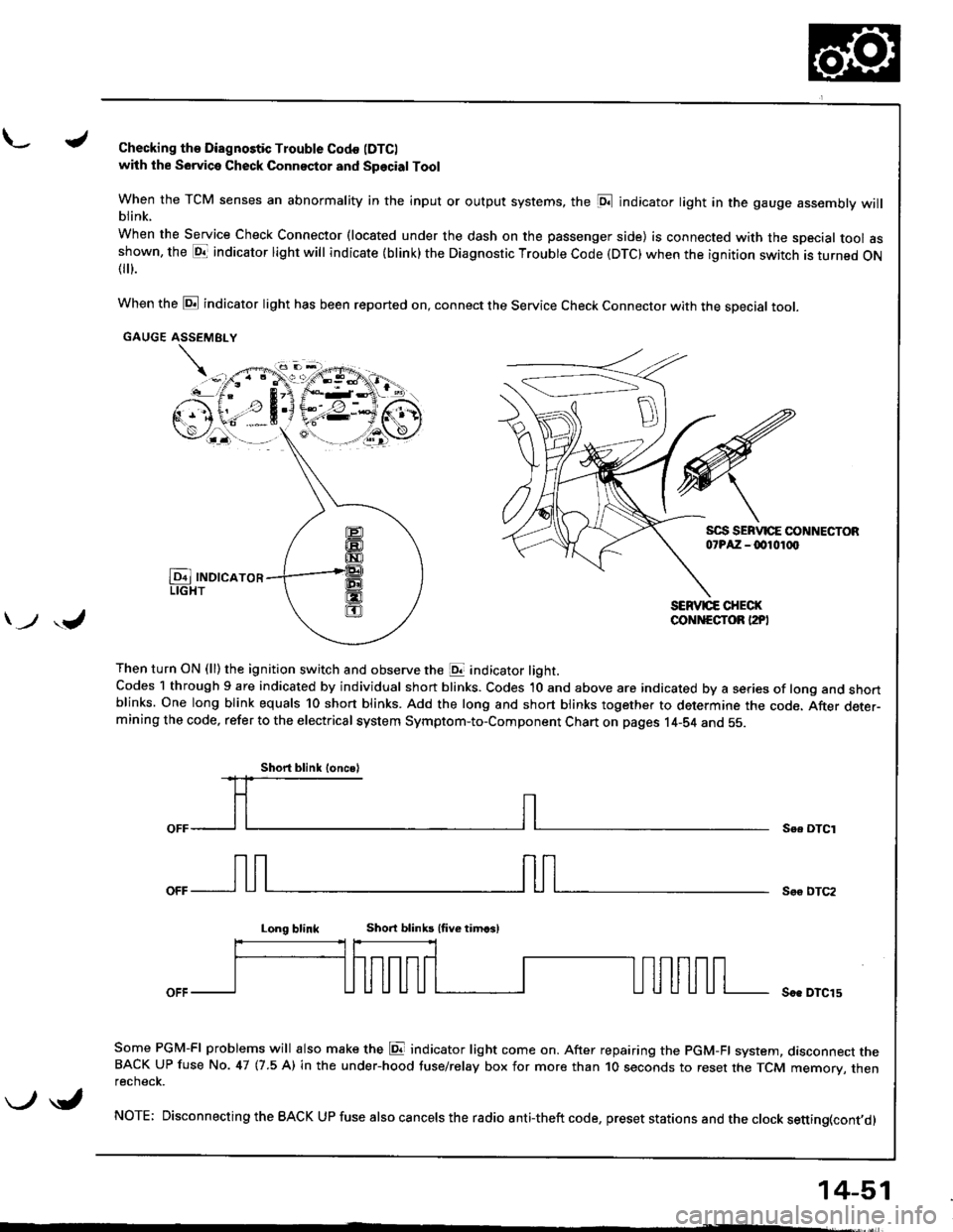
L./Checking th€ Diagnostic Trouble Codo (DTC)
with the Sowica Check Connector and Special Tool
When the TCM senses an abnormality in the input or output systems, the [D;l indicator light in the gauge assembly willblink.
When the Service Check Connector (located under the dash on the passenger side) is connected with the special tool asshown, the E1T indicator light will indicate (blink) the Diagnostic Troubte Code (DTC) when the ignition switch is turned ON{
}.
When the @ indicator light has been reported on, connect the Service Check Connector with the special toot.
GAUGE ASSEMEI.Y
Then turn ON (ll) the ignition switch and observe the E indicator light.Codes 1 through 9 are indicated by individual short blinks. Codes 1O and above are indicated by a series of long and shortblinks. One long blink equals 10 short blinks. Add the long and short blinks together to determine the code. After deter-mining the code, refer to the electrical system Symptom-to-Component Chart on pages 14-S4 and 55.
\-F;ii^r
) ,J
Se. OTCI
Soo DTC2
Long blinkShort blinb lfive timcsl
Soe DTCl5
Some PGM-FI problems will also make the E indicator light come on. After repairing the PGM-FI system, dasconnect theBACK UP fuse No. 47 (7.5 A) in the under-hood tuse/relay box for more than 1O seconds to reset the TCM memory, thenrecnecK.
NOTE; Disconnecting the BACK UP fuse also cancels the radio anti-theft code, preset stations and the clock setting(cont,d)
Short blink loncsl
\-/ \i,
14-51
Page 469 of 1680
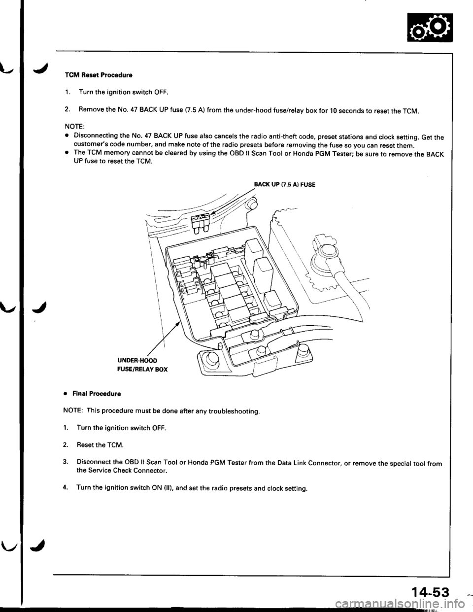
TCM Reset Procodure
1. Turn the ignition switch OFF.
2. Remove the No. 47 BACK UP fuse {7.8 A) from the under-hood fuse/relay box for lO seconds to reset the TCM.
NOTE:
. Disconnecting the No, 47 BACK UP fuse also cancels the radio anti-theft code, preset stations and clock setting, Get thecustomer's code number, and make note of the rsdio presets before removing the fuse so you can reset them.o The TCM memory cannot be cleared by using the OBD ll Scan Tool or Honda pGM Tester; be sure to remove the BACKUP fuse to reset the TCM.
BACK UP (7.5 A) FUSE
J
UNDER.HOOD
FUSE/RELAY BOX
. Final Procodurs
NOTE: This procedure must be done after any trou bleshooting.
1. Turn the ignition switch OFF.
2. Reset the TCM.
3. Disconnect the OBD ll Scan Tool or Honda PGM Tester from the Data Link Connector, or remove the sDecial tool fromthe Service Check Connector.
4. Turn the ignition switch ON (ll), and set the radio presets and clock setting.
14-53
Page 471 of 1680

u.drrf,,
J
J
J
14-55
Diagnostic
Trouble Code(DTC).
Ej
lndicator
Light
SymptomPossible CauseRefer to
Page
P1794
(131Blinks
. No specific symptom appears.. Short or open in LT GRN wire between
82 terminal and ECM. Faulty barometric pressure (BARO)
sensor
NOTE: BARO sensor is built into ECM.
't 4-7 4
P1786
(14)Blinks
. Transmission jerks hard when
shifting.
Short or open in FAS (YEL) wire
between 819 terminal and ECM
Faulty ECM
14-76
P0715
(15)Blinks
. Lock-up clutch does not engage,Disconnected mainshaft speed sensor
connector
Short or open in mainshaft speed sen-
sor wrre
Faulty mainshaft speed senso.
14-74
P0740
{ none,OFF. Lock-up clutch does not engage.Faulty lock-up control system14-80
P0730
I none,
. Fails to shift (between lst - 2nd,
2nd - 3rd, 1st - 4th. 3rd - 4th,
1st - 2nd - 3rd, 1st - 2nd - 4th,
1st - 3rd - 4th, or 2nd - 3rd - 4th
gears onry).. Fails to shift (stuck in 1st gears).
. Faulty shift control system
14-81
P0700
(none)
. Other automatic transmission problem (s)
Inspeclthe a utomatic transmission problem (s)accordingto the DTC (s)indicated with code m700.
(DTC)*: The DTCS in the parentheses are the codes the E indicator light indicates (blinks) when the service cnecK connec-tor is connected with the sDecialtool {SCS service connector).
NOTE: WhentheOBDll Scan Tool orHonda PGM Tester indicates the DTC(S) for the automatic transmission control sys-
tem, the scan tool or tester also indicates code P0700 simultaneously. Code P0700 means detection of some automatic
transmission problem on the PGM-Fl control system.
lf the self-diagnostic E indicator light does not blink. perform an inspection according to the table below.
NOTE:
. lf a custombr describes the symptom for code P1706 (6), P0725 (11) or P0715 (15), it will be necessary to recreate the
symptom by test-driving, then recheck the DTC,. Sometimes the E indicator light and the Malfunction Indicator Lamp (MlL) may come on simultaneously. lf so, check
the PGM-Fl system according to the DTC, then reset the memory by removing the BACK UP fuse in the under-dash
fuse/relay box for more than l0 seconds. Drive the vehicle for several minutes at a speed over 30 mph(50 km/h). then recheck the DTC.
. Disconnecting the BACK UP fuse also cancels the radio anti-theft code, preset stations and the clock setting. Get the
customer's code number, and make note of the radio presets before removing the fuse so you can reset them.
SymptomInspectionR€f. page
E indicator light does not come on for two seconds after ignition is
first turned on (ll).14-42
E indicator light is on constantly (not blinking) wheneverthe ignition is on {ll).14-84
Lock-up clutch does not have duty operation (ON - OFF).Check A,/C signal with Ay'C
on.14-85Lock-up clutch does not engage.
Shift lever cannot be moved from E position with the brake pedal
oeDresseo.Check brake switch signal.14-86
Page 645 of 1680
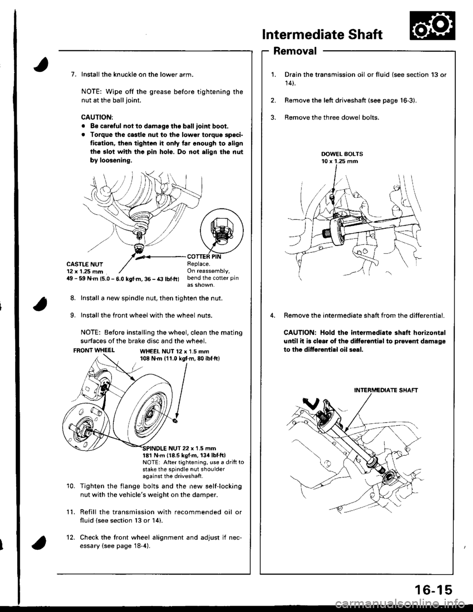
Intermediate Shaft
Removal
Drain the transmission oil or fluid {see section 13 or
14t.
Remove the left driveshaft (see page 16-3).
Bemove the three dowel bolts.
Remove the intermediate sh8ft from the differential.
CAUTION: Hold the intermediate shaft horizontal
until it is clear ot th6 difforantirl to prevont damage
to thc ditf€rential oil seal.
7. Install the knuckle on the lower arm.
NOTE: Wipe off the grease before tightening the
nut at the ball joint.
CAUTION:
. Be careful not to damago the ballioint boot.
. Torque the castle nut to tho low€r torque speci-
tication, then tighten it only lar onough to align
th6 slot whh tho pin hols. Do not align the nut
by loosening.
,.<__coTTEF PtNCASTLE NUT12 x 1.25 mm49 - 59 N.m {5.0 - 5.0 kgf.m, 36 - t3 lbl.ft)
Beplace.On reassembly,bend the cotter pin
8. Install a new spindle nut, then tighten the nut.
9. Installthe front wheel with the wheel nuts.
NOTE: Before installing the wheel, clean the mating
surfaces of the brake disc and the wheel.
FRONT WHEELWH€EL NUT 12 x 1.5 mm108 N.m (11.0 kgt m,80lbf ft)
10.
NUT 22 x '1.5 mm181 N m 118.5 kgl.m, 134lbtftlNOTE: After tightening, use a drift tostake the spindle nut shoulderagainst the driveshatt.
Tighten the flange bolts and the new self-locking
nut with the vehicle's weight on the damper.
Refill the transmission with recommended oil or
fluid (see section 13 or 14).
11.
12. Check the front wheel alignment and adjust if nec-
essary (see page 18-4).
INTERMCOIATE SHAFT
16-15
Page 751 of 1680
Brakes
Conventional Brakes ........ lg-1
Anti-lock Brake System (ABS) ............. 19-23