Page 928 of 1680
Seats
Rear Seat Replacement (cont'd)Rear Seat Cover Replacement
CAUTION: Wear gloves to.emove and install the sgat
covers.
NOTE:
a Take care not to tear the seams or damage the seat
covers,
a Remove the clips as shown.
8. Installalion is the reverse oI the removal procedure.
NOTE:
a Make sure the seat-back locks securely.
a lJ necessary, adjust the rear seat latch and
seat-back.
a Betore attaching the seat-back, side bolsters and
seat cushion, make sure there are no twists or
kinks in the rear seat belts and center belt.
a When installing the seat cushion, slip the seat belt
buckles through the slits in the seat cushion.
Remove the seat-back (see page 20-110).
Remove the latch cover and latch collar (see page
20-111).
Remove all the clips from rhe back of the seat back,
then Ioosen the seat-back cover.
Pull back the edge of the seat-back cover all the way
around. then release the clios.
Seat-back cover removal:
Hatchback
SEAT-BACK
H/HilflH
CLIP
CLIP
20-114
Page 930 of 1680
Seats
Rear Seat Cover
(cont'd)
Replacement
Sedan
Remove the seat cushion {see page 20-113).
Remove all the clips from under the seat cushion,
then loosen the seat cushion cove
SEAT CUSHIONCOVER
Pull back the edge of the seat cushion cover all the
way around, then release the clios
SEAT CUSHIONCOVER
Installation is the reverse o,f the removal procedure.
NOTE:
a To prevent wrinkles when installing a seat cover,
mark sure the material is stretched evenly over
the pad before securing all the clips.
a Replace the released clips with new ones.
UPHOLSTERY RING PLIERSCommercially available.
't.
2.
CLIP
CLIPS
20-116
NEW CLIP
Page 953 of 1680
Replacement
1. To remove the dashboard, tirst remove the:
a Front seats {see page 20-'103)
a Front and rear consoles (see page 20-130)
a Oashboard lower cover {see page 20-133)
a Knee bolster (see page 20-134)
. Glove box (see page 20-137). Clock (see page 20-1371
. Moonroof switch (see page 20-136)
a Stereo radio/cassette (see page 20-134)
2. Lower the steering column (see section 17).
NOTE: To prevent damage to the steering column,
wrap it with a shop towel.
l ; Boh, nut locations
AA : Bolr, 28
: Nut, 2
8 x 1.25 mm22 N.m 12.2 kgl.n,16 tbf.ft)o21 13 N m 11.3 kgl m,
\€J' Prbl rll
_Urr'rr,t __)
STEERING JOINTCOVER
STEERING COLUMN
3. Remove the nuts, then remove the front passenger's
airbag bracket.
: Nut locations, 4
6 x 1.0 mm L9.8Nm
{1.o kgt m,7.2tbt.rrUFRONT PASSENGEB'SAIRBAG
PASSENGER'S
SRS MAINAIRBAG BRACKET
HARNESS
4. Disconnect the air mix control cable and connectors.
AIR MIX CONTROLCABLE
HEATERCONTROLPANELCONNECTORS
(cont'd)
20-139
Page 1142 of 1680
Starter Reassembly
Starting System
Solenoid Plunger Inspection
Check the contact points and the face of the starter solenoid plunger for burning, pitting or any other defects. lfsurfaces are rough, recondition them with a strip of# 500 or # 600 sandoaoer.
POINT CONTACTINGFACE
NOTE: Use the illustration on page 23-81 as a reference
for reassembly.
1. Pry back each brush spring with a screwdriver, then
position the brush about halfway out of its holder,
and release the spnng to hold it there.
2. Install the armature in the housing. Next pry back
each brush spring again and push the brush down
until it seats against the commutator. then release
the spring against the end ol the brush.
SPRTNG
fi49-d
EI
VIR, ,\
li N,."
3. lnstall the end cover on the brush holder.
O-RING
23-86
Page 1189 of 1680

I
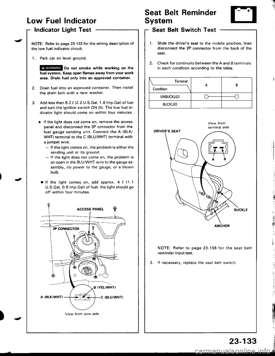
Seat Belt Reminder
SystemLow Fuel lndicator
Indicator Light Test
NOTE: Refer to page 23-123 for the wiring description of
the low fuel indicator circuit.
1. Park car on level ground.
@ oo not smoke whilc wolking on the
fuel system. Keep open tlames away from your work
area. Drain fuel only into an approved container.
2. Drain fuel into an approved container. Then install
the drain bolt with a new washer.
3. Add lessthan 8.2 t l2.2U.S.Gal, 1.8 lmp.Gal)of fuel
and turn the ignition switch ON {ll). The low fuel in-
dicator light should come on within lour minutes.
. lf the light does not come on. remove the access
panel and disconnect the 3P connector from the
fuel gauge sending unit. Connect the A (BLV
WHT) terminal to the C (BLU,/WHT) terminal with
a jumper wire.
- lf the Iight comes on, the problem is either the
sending unit or its ground.- lf the light does not come on, the problem is
an open in the BLU/WHT wire to the gauge as-
sembly, no power to the gauge, or a blown
bulb.
a lf the light comes on, add approx.4 ! (1.1
U.S.Gal. O.9 lmp.Gal) of fuel, the light should go
off within four minutes.
I
i
)
SeatSwitchTestBelt
1.Slide the driver's seat to the middle position. then
disconnect the 2P connector from the back of the
seat.
Check tor continuity between the A and B terminals
in each condition according to the table.
NOTE: Refer to page 23-156 for the seat belt
reminder input test,
3. lf necessary, replace the seat belt switch.
Terminal
c""dil----lB
UNBUCKLEDoo
BUCKLED
ANCHOR3P CONNECTOR
23-133
Page 1637 of 1680

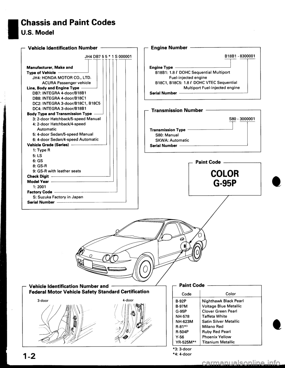
JH4DB755*1S000001
JH4: HONDA MOTOR CO., LTD.
ACURA Passenger vehicle
Line, Body and Engine Type
DB7: INTEGRA 4-door/81 881
DB8: INTEGRA 4-door/B1 8C1
DC2: INTEGRA 3-door/818C1, 818C5
DC4: INTEGRA 3-door/B1881
Body Type and Transmission Type
3: 2-door Hatchback/5-speed Manual
4: 2-door Hatch back/4-speed
Automatic
5: 4-door Sedan/S-speed Manual
6: 4-door Sedan/4-speed Automatic
9: GS-R with leather seats
S: Suzuka Factory in Japan
! Chassis and Paint Codes
I U.S. Model-
Vehicle ldentification Number and
Federal Motor Vehicle Safety Standard Certification
4-door
Paint Gode
COLOR
G-95P
'#19
'//dt
+3: 3-door*4: 4-door
81881
818B1: 1.8 f DOHC Sequential Multiport
Fuel-injected engine
818C1, 818C5: 1.8 f DOHC WEC Sequential
Multiport Fuel-injected engine
Paint Code
Nighthawk Black Pearl
Voltage Blue Metallic
Clover Green Pearl
Taffeta White
Satin Silver Metallic
Milano Red
Ruby Red Pearl
Phoenix Yellow
Titanium Metallic
B-92P
B-97M
G-95P
NH-578
NH-623M
R-81*3
R-504P
Y-56
YR-525M*4
1-2
./.4r//.'.
Page:
< prev 1-8 9-16 17-24