Page 1362 of 1680
)
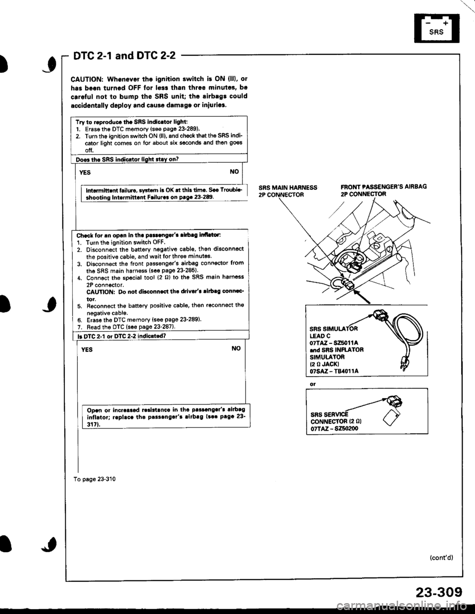
DTC 2-1 and DTG 2-2
CAUTION: whenevor tho ignition switch it ON (lll, or
has bc€n turnod OFF lor le$ thsn thros minutos, b.
carolul not to bump th€ SRS unit; the airbagt could
accidontslly deploy and csuse damsga or iniurica,
lntormitt nt failurc, sy3t.rn b OK rt this lima Saa lroubL_
Iniarmittant Friluraa on paq. 23-2&l
Char* for an opan in tha pataangal'a alrbag lr Llor:
1. Turn the ignition switch OFF.
2. Oisconnect the bauery n6gative cabl€, then di6conn6ct
the positive cable, and wait lor thr€o minutes.
3. Disconnect the front passonger's airbsg conn€ctor trom
the SRS main harness (s6€ paoe 23'285).
4. Connect th6 sDecial tool {2 o} lo th6 SRS main hatnoss
2P connoctor.CAUYIO : Oo not ditconn.ct th. drivo/t ritb.g conn.c'
tor.5. R6conned the banery positive cablo. then r6connect tho
negative cabl6.Erase tho DTC memory {s6o page 23-289).
Read the DTC (see page 23-287).
Try to raproduc. th. SRS indicltot light:1. Er6s6 th6 DTC memory {seo page 23-289).2. Turn the ignition swhch ON (ll), and ch€ck thst the SRS indi-
cator light comes on for about six seconds and then goeg
off.
l. DTC 2-1 or DTC 2-2 indiclted?
Ooan or incraaaod ].3ialrnca in tha paaaangar'a rilbag
intlaior; raphca tha paaaangar't !irbag (!a. prga 23-
317).
ot
(cont'd)
23-309
Page 1364 of 1680
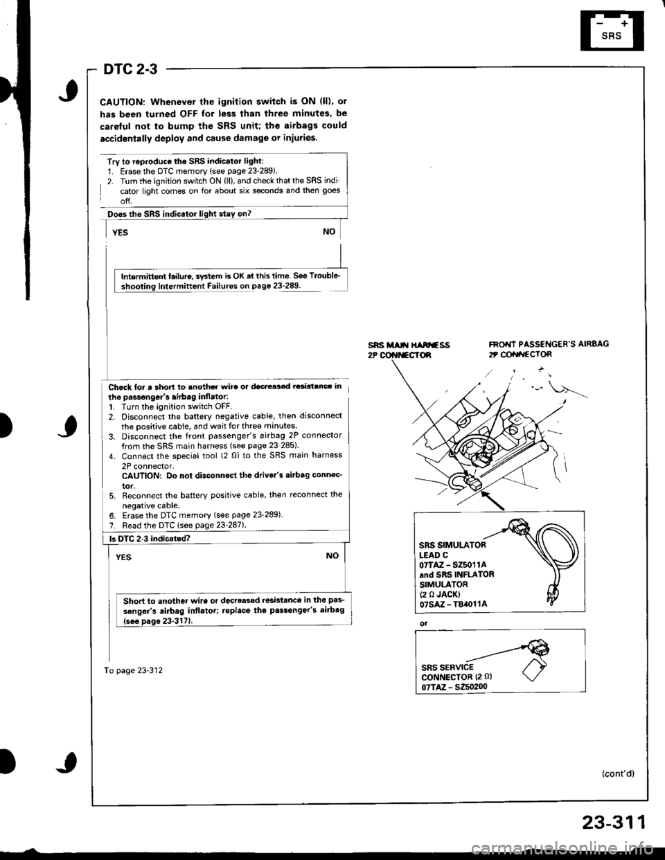
DTC 2-3
CAUTION: Whenever the ignition switch is ON (ll), or
has been turned OFF for less than three minutes, be
careful not to bump the SRS unit; the airbags could
accidentally deploy and cause damage or injuries.
Try to reproduce the SRS indicatol light:1. Erase the DTC memory (see page 23-289).
2. Turn the ignition switch ON (ll), and check that the SRS indi
cator light comes on for about six seconds and then goes
off.
Doos th€ SRS indicator
Chsck loa a short to anothcr wirc or dacacelod rarinanc. in
the passongGr'3 airb.g inflator:1. Turn the ignition switch OFF.2. Disconnect the baftery negative cable, then disconnect
the positive cable, and wait for three manutes
3. Disconnect the front passenger's 6irbag 2P connector
{rom the SRS main harness (see page 23 285)
4. Connect the special tool (2 0) to the SRS main harness
2P connector,CAUTION: Do not disconnect the drive/s .i.bag conn€c_
tor,5. Reconnect the batterY positive cable, then reconnect the
neoative cable.
s*i M t{ HIArfss2P @r{t*cTd
FNO'IT PASSENGER'S AIRBAG
2t @tat{ccTon
)
lntermittent failur€, svstem is OK ai this time. See Troubl6-
Intermittent Failures on page 23-289.
6. Erase the DTC memory (see page 23-289)
7. Read the DTC (see page 23'247l.
To page 23-312
|3 DTC 2-3 indicat.d?
Short to another wire or decreased resislance in the pas-
sengsr's airbag intlatot; teplace the p.$onger's aitbag
SRS SIMULATORLEAD C07TAZ - SZ50'r 1Aand SRS INFLATORSIMULATOR(2 0 JACK)07sAz-T84011A
ol
23-311
Page 1366 of 1680
\
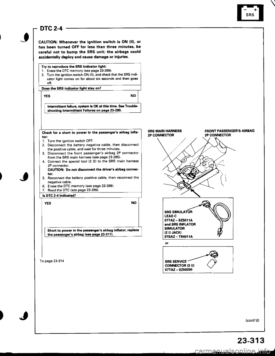
DTC 2-4
CAUTION: Whenevor th6 ignition switch is ON (ll), or
has been turned OFF for less than threo minutcs, be
car€ful not to bump lhe SRS unit; the airbEgs could
accidontslly dcploy and cause damag€ 01 iniuries.
SRS MAIN HABNESS2P CONNECTORFRONT PASSENGER'S AIRBAG
2P CONNECTOR
ot
SBS SERVICEcoNNECTOR {2 0l07TAZ - SZ5o200
(cont'd)
23-313
_-t
)
Try to roproduce th. SRS indicrtor lighl:1. Erase the DTC memory (see page 23-289).2. Turn the ignition switch ON (ll), and chock that the SRS indi-
cator light comes on for about six seconds and then goes
off.
Do.3 th. SRS indicator lighi stay on?
NOYES
Ini.rmitt.nt t iluro, !y*em b OK .t thb timo. Soe Ttoubl+,
shooting lmormittent Failuraa on P.ge 23.289
Ch6ck tor a 3hon to powol in tha pa3tonga/t lirbag infla_
to.:1. Turn the ignition switch OFF.2. Disconnect the battory negative cable, then disconnect
the oositive cable, and wait tor three manutes
3. Disconnect the front passenger's airbag 2P conn€ctorIrom the SRS main harnoss (see page 23-285).
4. Connect the soecial tool (2 0) to the SRS main harness
2P connector.CAUTION: Do not dilconn.ct tho driv.l'! .irb.g conn.c'
tor.5. Reconnect the battery positive cable, then reconnoct the
negative cable.6. Erase the DTC memory (see page 23-289).7. Read the DTC (see page 23-2861.
b DTC 2-4 indicatcd?
YESNO
Short to powor in th. pa$anoar'3 airbrg infldtor; tepl&t
the Dass6nqor'3 .irbaq {sco prgc 23-3171
To page 23-314
07TAZ-SZ50t1A.nd SRS INFLATORSIMULA'OR(2 0 JACKT07sAz - TB()11A
Page 1368 of 1680
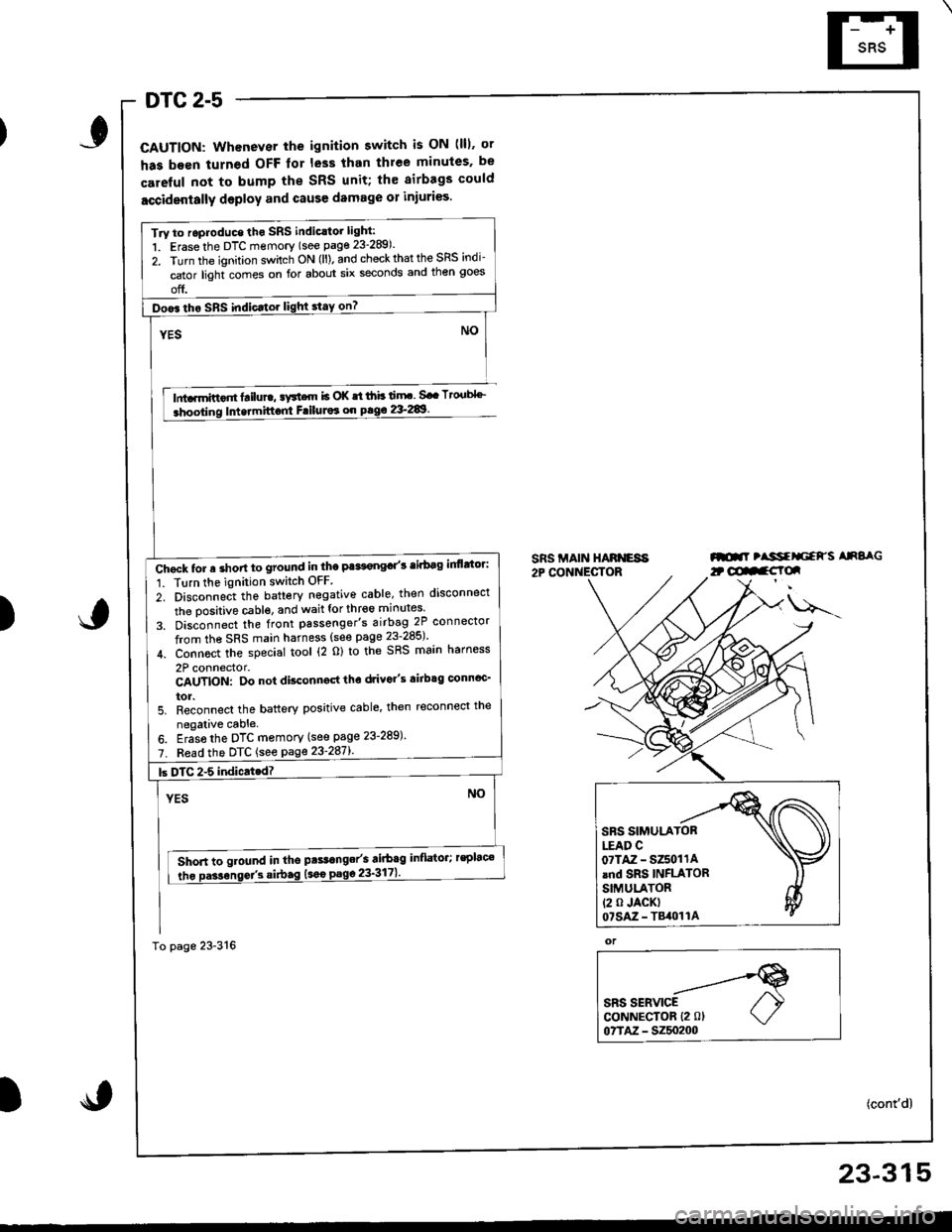
DTC 2-5
CAUTION: Whenever the ignition switch is ON (lll. ot
has been turned OFF lor less than thlee minules. be
careful not to bump the SRS unit; th€ airbags could
accidentally deploy and cause damage 01 injuri€s.
lnta.mittor tailure, aFtcrn b OK st ihb ti.rF. Sa. Tto.tbl''_
Intermittont FriluJor on pag€ 2&289.
SRS MAIN HARNESA2P CONNECTORml tlssfrliaFs AnSaG
)
u---
or
SRS SERVICECoNNECTOR {2 0lo?TM - 5250200
(cont'd)
Try to roproduce tho SRS indic.tor light:
1. Erase the DTC memory (see page 23-289).
2. Turn the ignition sv/itch ON (ll). and check that the SRS indi-
cator light comes on for about six seconds and then goes
off.
Doo6 tho SRS indic.tor light stay on?
Chgck tor a short to ground in the Pa*t€ngd'3 tirbag inflttor:
1. Tlrn the ignition switch OFF
2. Disconnect the battery negative cable, then disconnect
the oositive cable. and wait for thr€6 minutes
3. Dis;onnect the front passenger's airbag 2P connector
from the SRS main harness (see page 23-285)'
4. Connoct the special tool (2 o) to the SRS main harness
2P connector.CAUTION: Do not disconngd tho drivo"s airbtg connoc'
tor.5. Reconnect the battery positive cable' then reconnect the
negalive cable.
6. Eras6 the DTC memory (see page 23-289)'
7. Fead the DTC {see page 23'287l'.
Short to ground in tho pts.range/s airbag inflator; rsplac€
tho Da3sonse/3 si.bag (sao
23-315
Page 1372 of 1680
I
I
6. Reconnect the airbag connector(s).
Front Passenger's Side:
. Attach the airbag connector to the connector holder.
then reinstallthe glove box.
CONNECTOR HOLDER
Driver's Side:
. Connect the driver's airbag 2P connector to the cable
reel 2P connector, then rnstall the access panel on the
steering wheel.
\,
23-319
7.Connect the baftery positive cable, then connect thenegative cable.
After installing the airbag, confirm proper system
operal|on:
. Turn the ignition switch ON (ll); the SRS indica-
tor light should come on for about six seconds
and then go off.
. Make sure both horn buttons work.
. Take a test drive, and make sure the cruise con-
trol switches work.
Enter the anti-theft code for the radio. then enter the
customer's radio station presets,
9.
Page 1374 of 1680
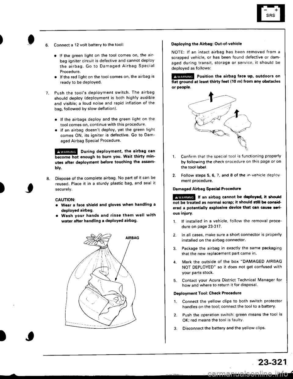
)6.
7.
8.
Connect a 12 volt battery to the tool:
. lf the green light on the tool comes on, the alr-
bag igniter circuit is defective and cannot deploy
the airbag. Go to Damaged Airbag Specia I
Procedure.
. lfthe red light on the tool comes on, the airbag is
ready to be deployed.
Push the tool's deployment switch The airbag
should deploy (deployment is both highly audible
and visible; a loud noise and rapid inflation of the
bag, followed by slow deflation).
. lf the airbags deploy and the green light on the
tool comes on, continue with this procedure
. lf an airbag doesn't deploy. yet the green light
comes ON, its igniter is defective. Go to Dam-
aged Airbag Special Procedure.
!!@ During deployment, the airbag c8n
become hot enough to burn you Wait thirtY min-
ut€s after d€ployment befote touching the assem-
blv.
Dispose of the complete airbag. No part of it can be
reused. Place it in a sturdy plastic bag, and seal it
securery.
CAUTION:
. wear a lace shield and gloves when handling a
deployed airbag.
. Wash your hands and rinse them well with
water after handling a deployed sirbag
)
Deploying the Airbag: Out-ot-vehicle
NOTE: lf an intact airbag has been removed from a
scraDDed vehicle, or has been found defective or dam-
aged during transit, storage or service, it should be
deoloved as follows:
@@ Position th€ airbag laca up. outdoors on
tlat ground at l€ast thirty leet (10 m) ftom any obstacles
or people.
1. Confirm that the special tool is functioning properly
by tollowing the check procedure on thls page or on
the tool lab€|.
2. Follow steps 5, 6, 7, and 8 ol the in.vehicle deploy'
ment orocedure.
Damaged Airbag Sp€citl Procedurc
!@ [ an airbag cannot be d.ploytd, h 3hoold
not be lreated as normal scrap; it should 3till b. corlrkl
ered a polentially sxplosive device that can clura tari
ous iniury.
1. lf installed in a vehicle, follow the removal proce-
dure on page 23-317.
2. ln all cases, make sure a short connector is properly
installed on the airbag connector.
3. Package the airbag in exactly the same packaging
that the new replacement part came In.
4. Mark the outside of the box "DAMAGED AIRBAG
NOT DEPLOYED" so it does not get confused with
your Parts stock.
5. Contact your Acura District Technical lvanager for
how and where to return it for disposal.
Deployment Tool: Ch€ck Ptocedure
1. Connect the yellow clips to both switch protector
handles on the tool; connect the tool to a battery
2. Push the operation switch: green means the tool is
OK; red means the tool is faultv.
3. Disconnect the battery and the yellow clips
23-321
Page 1378 of 1680
Instsll the steering wheel bolt, then install the driv-
er's airbag.
TORX BOLTS9.8 N m {1.0 kgf'm,7.2 lbtftlReplace.U3e . Torx T30 bit.
STEERING WHEEL NUT19 N.m (5 kgl.m, 36 lbl.ftl
Anach the 2P and 3P connectors to the connector
holder. then install the knee bolster and dashboard
lowgr cover,
le
CONNECTOR HOLDER
DASHBOARD LOWER COVER
23-325
\
'19. Reconnect the driver's aibag 2P connector to the
cable reel 2P connector, and reinstSll the access
panel on the steering wheel.
20, Reconnect the battery positive cable, then the nega-
tivs cable.
21. After installing the cable reel, confirm proper sys-
tgm operation:
Turn the ignition switch ON (ll); the SRS indica-
tor light should come on for about six seconds
and thsn go off.
Make surs both horn buttons work.
Make sure the headlight and wiper switches
Go {or a test drive, and make sure the cruise con-
trol switches work.
Ent6r the anti-theft code for tho radio, then enter the
customsr's radio station presets.
a
a
Page 1380 of 1680
6, Install the new SRS unit.
o^ l- o
9.8 N.m 11.0 kgf m, 7.2Use a Torx T30 bit.
I
TORX BOLTS9.8 N.m 11.0 kgl.m, 7.2 lbf'ftlUse a Torx T30 bit.
7.Connect the SRS main harness l8P connector to the
SRS unit; push it into position until it clicks.
Install the SRS unit covers (right and left) Make
sure the covers snap together in the middle.8.
,l
\
10.
Reconnect the driver's airbag 2P connector to the
cable reel 2P connector, then reinstall the access
panel on the steering wheel.
Reconnect the front passenger's airbag connector
to the SRS main harness.
Reconnect the battery positive cable, then the nega-
tive cable.
After installing the SRS unit, confirm proper system
operation: Turn the ignition switch ON (ll); the SRS
indicator light should come on for about six seconds
and then go off.
11.
12.