Page 1458 of 1680

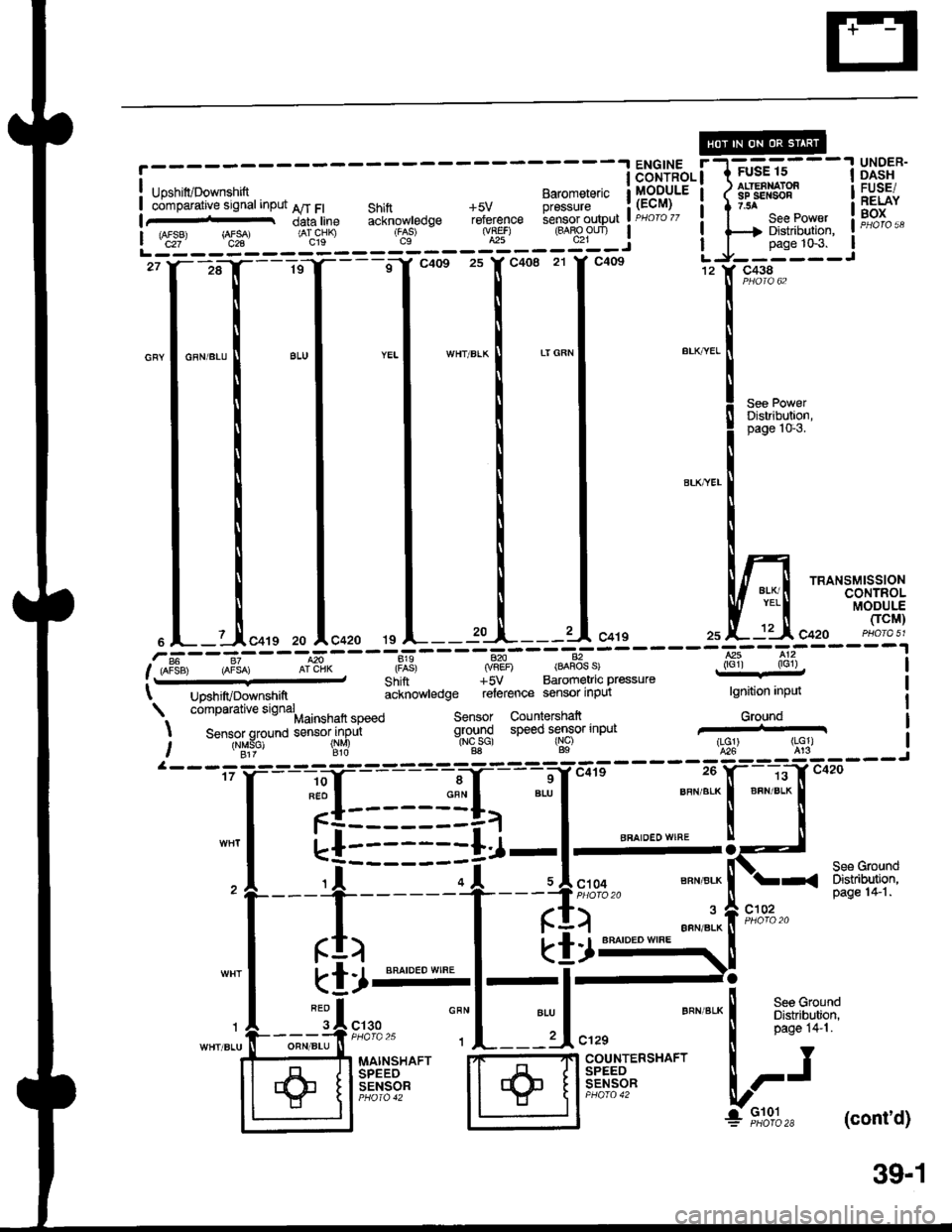
r------- ENGTNE r-l=.=-----1 UNoER
! Upsnir/Downsrrirt 8",",'",.,'" lllSBltE'i lil€Effis" il|FlJ| 6Smpititiue s'gnatinput AT Ft Shift +5v pressure i (Er,M, I I z.$ i 3:$"|+o"t"^tin."acknow|edqereferenc€iensoroutput|r,.c'c;::|seePo1:;.iFH;%",
i ,frT, rArsA, iiicsn .S' - *) (BABPun | | |--| Distribul
r------- ------ j | 'l-
- oaoe to+ l
27 Y--,;a--- -- t - =o1-c-co- -s-y--+oe zr y-noe l"J--^i""- -- - J
o l--l*tcars zo !c+zo ts A--- tu-I----'l c+ts 25 A--:'-'' c42o PHora 51
.?iF---et----,6-----di?----iry_------ql-------E:--?:------11.,oF3", a"{o, ofl"'n* .f*: jfit' Bj:l:4"',.::p,""",," . iroir , ,nct) |t uo"r,,rvooin"n*, icinorvteoge rJGrence sCnior inpui tgnition inpui
. comparative signahainsnaft speeo sensor countershalt Ground
I Sensor qround sensor inpu ground speed sensor input
I
-- -.gir- - gig lNcsc) rNc) i!3J t!91, ("$T)
a---------17 r--1;
iI= = =+a
""'
"*,*. *,""1*
"[5
-'
tl-,Jti*.
--?+T*'
:::h#
-*
FFlHT.-
rI) I ktll'rs::::::
-+--El r \:
-!r-l-l--
-r"-tlr*,.
":"L--d",,, """"'*l
fu?t:F'
MAINSHAFT PTF
+ ili.Ei:,?" ;1 ffiili""r:""^" L-J
+ F,t"%" (cont'd)
39'1
+
Page 1462 of 1680
UNOER-OASHFUSE/RELAYBOX
c438
See PowerDistribution,page 10-3.
c410----.---
I Po,"iu3.-iii"" to,.I solenoid valve
12
POWEBTRAINMODULE(PCM)
c457
Ground(rG1)820
n['
-i
20
BRN/BLK
BBAIOED WIFIE
Mainshaft speed Sensor Countershaftsensor{input qL?T"9 speed sensor input
011 016 D10==-T,I____:,!T,-------"'il",'.
f|:::::::[]-l-
li------;I- ul",oo
rI" I [Ij.,=
'.fi"-l_-l;
) ff*s
:;I
rl
cl02
See GroundDistribution,page 14-1.
(cont'd)
BFN/ALK
BFN/BLK
MAINSHAFTSPEEDSENSOR
COUNTERSHAFTSPEEDSENSOR
++
39-5
Page 1463 of 1680
Automatic Transmission Controls
- '00 Model (cont'd)
[---;""'.f
-lc+os 141' c4o8 LJ-:*:IJ
|
:t
, ;:".1
*"",",1 "**-
I
-.11,[t*r'""
I .l ,.,1,","" .J,o*". i
r*ru;l
i.";-
- - -
Is"*
- - - - -
Fsil
- - -
;; I i.l{T'Fil^'- i I ;;
- -
I Ui3"*I voltage Inout
L js!'- - - - - - d": - - - - - 3t - - - - - roql j Hili:
i i-Ti*.*,*,, i F"H*i,'ll-------zrI_------16'rc4os 14tr' c408 LJ_j*::J
:tt, I ".ou.*l I I
r rii ^ r "."-,. r ^""",. r ". ::[ 9#3-
**[
[ [ X"., !r*g+;l"f-----
t
't
l;:,.il*[;,;
""T1",,,""
! ! !i;T-"{_
___-}.[1dnw'"t*il *"*-l "'o*n'l i'I---L-
I I NLi::--::::-:=a-*$$ti
.l_______l ",,, ,l ",,.
'r "*'
I_ITI ENGINE COOLANT
iddirioil I Jr l,.g:tilu;SENSOR lJJal PHora 17
c106
GFN/BLK
SERVICE CHECK CONNECTORPHOIO 76
-"^,:,[
.:
"{
'T[_:'*' "..1
;*liil, lFffi*'" I
c405
BLI
BLK I
I'
See GroundDistribution,pages 14-4and 14-5.
V
I ..
G401
39-6
Page 1466 of 1680
Anti-Lock Brake System (ABS)
iTffi;---IH5BE"
tlSrqr$llilHh1,
UNOER.DASHFUSE/RELAYBOX
FUSE 16
EEiFf a ) IESYD€F...'EB 1."-9 ii1gl7sA Distribution,
Lf:je:l- JPPJ",,---------+ pags 1G6.
__li;;,
"-",['*'*-
,
ffi_-GAUGEASSEMBLY
[-4];"ffi]":+*" I if^",T*fl-;.r-ini -
i_ il*6$?jq*
.-1- N"""-l illT*ffi
o"n,n",l $
"-^*"
1
L-:L--- -'L------'
! ir'J'.f,,il'*" i
"-:i[-, -"tl
,*,***t
f=fii1ina*15.17, I*',1*,rtil Ilm
! """ i pirjli-io.6. i ^. 1 +seerndicators
-r,Llll----_.#.
ffifi'fj
LEFTFRONTWHEELSENSOR
RIGHTFBONTWHEELSENSOR
LEFTREARWHEELSENSORPHOTA 46
RIGHTREARWHEELSENSOR
44
Page 1478 of 1680

A/C Gompressor Controls (conrd)
- How the Circuit Works
Battery voltage is supplied through fuse 56 to the
A,/C compressor clutch relay contacts at all times.
With the ignition switch in ON (ll), voltage is applied
to the coil of the A,/C compressor clutch relay
through fuse 17. When you push the A,/C switch
ON, and the heater fan switch is in posation 1, 2, 3,
or 4, a "ground" input is provided to the engine or
powertrain control module (ECM or PCM) through
the A,/C thermostat and the A,/C pressure switch.
The A,/C compressor clutch relay is grounded by the
engine or powertrain control module (ECM or PCM).
When energized, the A,/C compressor clutch relay
allows battery voltage to turn on the A,/C
comDressor clutch,
The A,/C ON indicator light comes on when the A"/C
system is requested.
A,/C Thermostat
The A,/C thermostat is located on the evaoorator
housing. The AJC thermostat turns off the A,/C
compressor clutch if the temperature at the
evaporator goes below 3'C (37'F). This prevents
condensation from freezing on the evaporator fins
and blocking the air delivery into the passenger
compartment. The blower motor will keep running
when the sensor lurns off the compressor.
A,/C Pressure Switch
The A,/C pressure switch is located in the condenser
outlet line where refrigerant is in a high
temperature/high pressure liquid state. The switch
will sense abnormally high or low pressure, and
open the circuit. This removes ground, and the
compressor will stop running.
Refer to the Service Manual (Section 22,
Air Conditioning) for specific tests or
troubleshooting procedures.
62-2
Page 1499 of 1680

Gauges (cont'd)
- How the Circuit Works
When the ignition switch is in ON (ll) or START (lll),
battery voltage is supplied through fuse 25 to the
gauges in the gauge assembly.
Speedometer and Odometer
The odometer and speedometer drive circuits
receive pulses lrom the vehicle speed sensor
(VSS). The pulse rate increases as the car
accelerates. The frequency and duration of these
input pulses are measured and displayed by the
speedometer, odometer and tripmeter.
Tachometer ('98-'99 Models)
The tachometer drive circuit receives oulses from
the ignition control module (lCM) in the distributor
assembly. The solid-state tachometer then displays
these pulses as engine speed. For each 200 pulses
per minute from the ignition control module (lCM),
the tachometer displays 100 RPM.
Tachometer ('00 Model)
The tachometer drive circuit receives pulses f rom
the PCM or ECM. The solid-state tachometer then
displays these pulses as engine speed. For each
200 oulses oer minute trom the PCM or ECM the
tachometer displays 1 00 RPM.
Engine Coolant Temperature Gauge and Fuel
Gauge
The engine coolant temperature gauge has two
intersecting coils wound around a permanent
magnet rotor. Voltage applied to the coils, through
fuse 25, generates a magnetic field. The magnetic
field, controlled by the engine coolant temperature
gauge sending unit, causes the rotor to rotate and
the gauge needle to move. As the resistance in the
sending unit varies, current through the gauge coils
changes. The gauge needle moves toward the coil
with the strongest magnetic tield. The fuel gauge
works the same way.
The engine coolant temperature gauge sending
unit's resistance varies from about 137 ohms at low
engine temperature to between 30-46 ohms at high
temperature (radiator fan running).
The fuel gauge sending unit's resistance varies from
about 2-5 ohms at full, to about 110 ohms at empty.
When you turn the ignition switch to LOCK (0), the
gauge remains at the last reading until you turn lhe
ignition switch to ON (ll) or START (lll) again.
Refer to the Service Manual (Section 23, Electrical)
for specific tests or troubleshooting procedures.
81'2
Page 1500 of 1680
Maintenance Reminder Light
i-T;;-l
t-IY--i
,"",,":lt*'
i
UNDER.HOODFUSE/RELAYBOX
aaa4
""rr"a"
I
:'^.:tr'--'
!aaE�+
"-",l_
Sse Pows.Distribulionpsge l0{.
Ssg PowsrDisribr.rtlonpage iGS.
MAINTENANCEREMINDERUNIT
F
;ilr
""'
a
onr I
F:"?l F"x%''�
arr-<
"T
I'*""T
I "',,
"--:i:;;"
r-.=-l vEHlcLEI venrcle I SPEEDI speed ! SENSORI outpur | rySS)L__J PHaro 26
See VehicleSpeed Sensor(vss)
lgnitionlnp{.rtMaintenancer€mnoarlight conlrol
GfoundVehicle spe€dinput
83
Page 1501 of 1680

How the Circuit Works
The maintenance reminder light comes on to
remind the driver that the car is due for
scheduled mainlenance.
The maintenance reminder unit receives a vehicle
speed input from the vehicle speed sensor (VSS)
and uses this inlormation to compute the distance
traveled. For the first 6000 t 1 00 miles (9650 t 160
km) after the maintenance reminder light is reset, it
will come on for two seconds when you turn the
ignition switch to ON (ll) as a bulb check.
Between 6000 1 100 miles (9650 t 160 km) and
7500 t 100 miles (12070 I 160 km) the reminder
light will come on for two seconds when you turn
the ignition switch to ON (ll), and then flash for eight
seconds more.
Beyond 7500 t 100 miles (12070 t l60 km) the
reminder light will stay on when the ignition switch is
in the ON (ll) position until the unit is reset.
To reset the unit, the car must be parked and the
ignition switch in the ON (ll) position. Press the
reset button on the unit and hold it there for more
than three seconds, and the reminder light will
go off.
Refer to the Service Manual (Section 23, Electrical)
for specific tests or troubleshooting procedures.
83-1