Page 1177 of 1680
Gauge/lndicator/Terminal Location Index
coNNECTOR "8" (C5601
ltrii
rll
coNNECTOR "C" (Css8l
ACHOMETER:rdicates 10O rpm al
OO pulses per minutef the ignition controlrodule {lCM).
81 ------------ 816
ililllllilll
A,/T GEAR POS]TIONINDICATOR SYSTEMS€e page 23-140
c1 ------>cl0
I
Jilliltl
atespage 23-131t Test, page 23-132
^a1(
u;" u
7' /'- /n.u (,w.--
" oe)\r- -7 ttt'-1 r --
I 'l I z{.-a\y' | \-./^l
!t tr--',9I I l\-//11, I t,-\Jl
.r' to"-ei
I :rl
F<
elrle
ENGINE COOLANT TEMPERATUREGauge T€st, page 23-134Sending Unit Test, page 23'134
IECTI GAUGE:
A1 ----> A5
D1-------->D13
ililtl|illl
SPEEOOMETER:lndicates (60 mph at 1025 rpm) or
{60 km/h at 637 rpm) of the
vehicle speed sensor {VSS).
coNNECTOR "A" (C557)
coNNECTOR "D" (C5591
23-121
Page 1184 of 1680
Vehicle Speed Sensor (VSSI
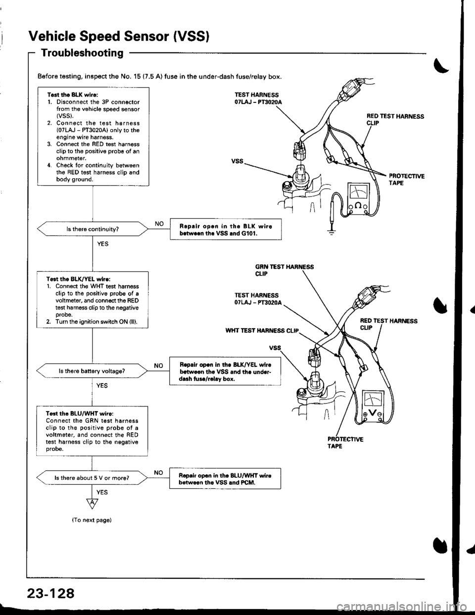
Troubleshooting
{To next page)
REO TEST HARNESS
PBOTECTIVETAPE
Test tho 8LK wiro:1. Disconnect the 3P connectorfrom the vohicle speed sensor(vss).
2. Connect the test harness(07LA,J - PT3020A) only to theengine wire harnoss.3, Connect the RED test harnessclip to the positive probe of anohmmel€r.4. Check for continuity betwoenthe RED test harness clip andbody ground.
Roplir op.n in th. BLK wirob.tw..n tha VSS .nd G101.
To3t thc BLK/YEL wiro:1. Conn6ct th€ WHT test harnessclip to the positive prob€ of avoltmeter, and connect the REDt€st harness clip to the nogativeprobe.2. Turn the ignition switch ON (lll.
R.p.lr op.n In tho BLK/YEL wirebrtw..n th. VSS and th. under-dr.h tu../r.l!y box.
Tort th. BLU/WHT wiro:Connect the GRN test harnessclip to the positive prob€ ot avoltmeter, and connect the REDtest harness clip to the nggatjveprobe.
Roprh op.n in th. 8LU/WHT wireb.tw.on tho VSS lnd PCM.ls there about 5 V or more?
Before testing, inspect the No. 15 (7,5 A) fuse in the under-dash fuse/relay box.
GRN TESTCLIP
TEST HARNESSOTLAJ - PT3O2OA
w'{T TES? HARIVESS CLIP
TAPE
23-128
Page 1186 of 1680
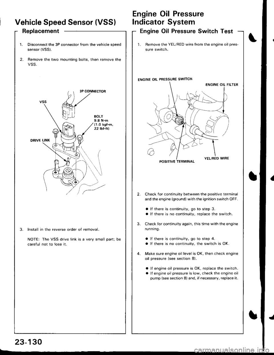
1. Disconnect the 3P connector from the vehicle speed
sensor (VSSl.
2. Remove the two mounting bolts, then remove the
VSS.
3P CONNECTOR
BOLT9.8 N.m(1.O kgf.m,22 tbt,ltl
DRIVE LINK
3.Install in the reverse order of removal.
NOTE: The VSS drive link is a very small part;
careful not to lose it.
DC
Vehicle Speed Sensor (VSS)
Engine Oil Pressure
lndicator System
ReplacementEngine Oil Pressure Switch Test
23-130
E-_
1 . Remove the YEL/RED wire trom the engine oil pres-
sure swlrcn.
ENGINE OIL PBESSURE SWITCH
Check for continuity between the positive terminal
and the engine (ground) with the ignition switch OFF.
a lf there is continuity, go to step 3.
a lf there is no continuity, replace the switch.
Check lor continuity again, this time with the engine
running.
a lf there is continuity, go to step 4.
a lf there is no continuity, the switch is OK.
Make sure engine oil level is OK, then check engine
oil pressure (see section 8).
a lf engine oil pressure is OK, replace the switch.
a lf engine oil pressure is low, check the engine oil
pump (see section 8) and, iI necessary, replace it.
2.
3.
POSITIVE TERMINAL
Page 1192 of 1680
MAINTENANCE BEMINDER LIGHT{ln the gauge assembly)Gauge Assembly. page 23-120
VEHICLE SPEED SENSOR IVSS)(On th6 transmission housing)Test, page 23-128, 129Replacement, page 23-130
MAIMTENANCE REMINDER UNIT(Behind th€ dashboard lower cover)Input T6st, page 23-139
Maintenance Reminder System
Component Location Index
\
t
23-136
I
Page 1193 of 1680
t
{)
)
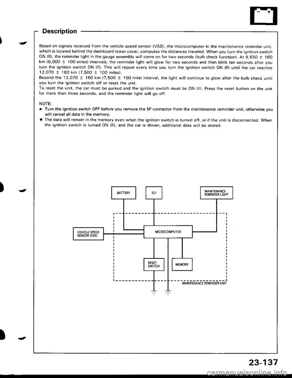
Based on signals received from the vehicle speed sensor (VSS). the microcomputer in the maintenance reminder unit,which is located behind the dashboard lower cover, computes the distances traveled. When you turn the ignition switchON (ll), the reminder light in the gauge assembly will come on for two seconds (bulb check tunction). At 9,650 1 160km {6,000 1 1O0 miles} intervals, the reminder light will glow for two seconds and then blink ten seconds after you
turn the ignition switch ON (ll). This will repeat every rime you turn the ignition switch ON {ll) until rhe car reaches12,O7O ! 1 60 km (7,500 t 100 miles).
Beyond the 12.o1O ! 160 km (7,5OO t IOO mile) interval, the light will continue to glow after the bulb check untilyou turn the ignition switch otf or reset the unit.
To reset the unit, the car must be parked and the ignition switch must be ON (ll). Press the reset button on the unitfor more than three seconds, and the reminder light will go off.
NOTE:
. Turn the ignition switch OFF before you remove the 5P connector from the maintenance reminder unit, otherwise vouwiil cancel all data in the memory.
a The data will remain in the memory even when the ignition switch is turned off, or if the unit is disconnected. Whenthe ignition switch is turned ON (lll, and the car is driven, additional data will be stored.
{
23-137
Page 1195 of 1680
Maintenance Reminder Unit Input Test
)
v
t
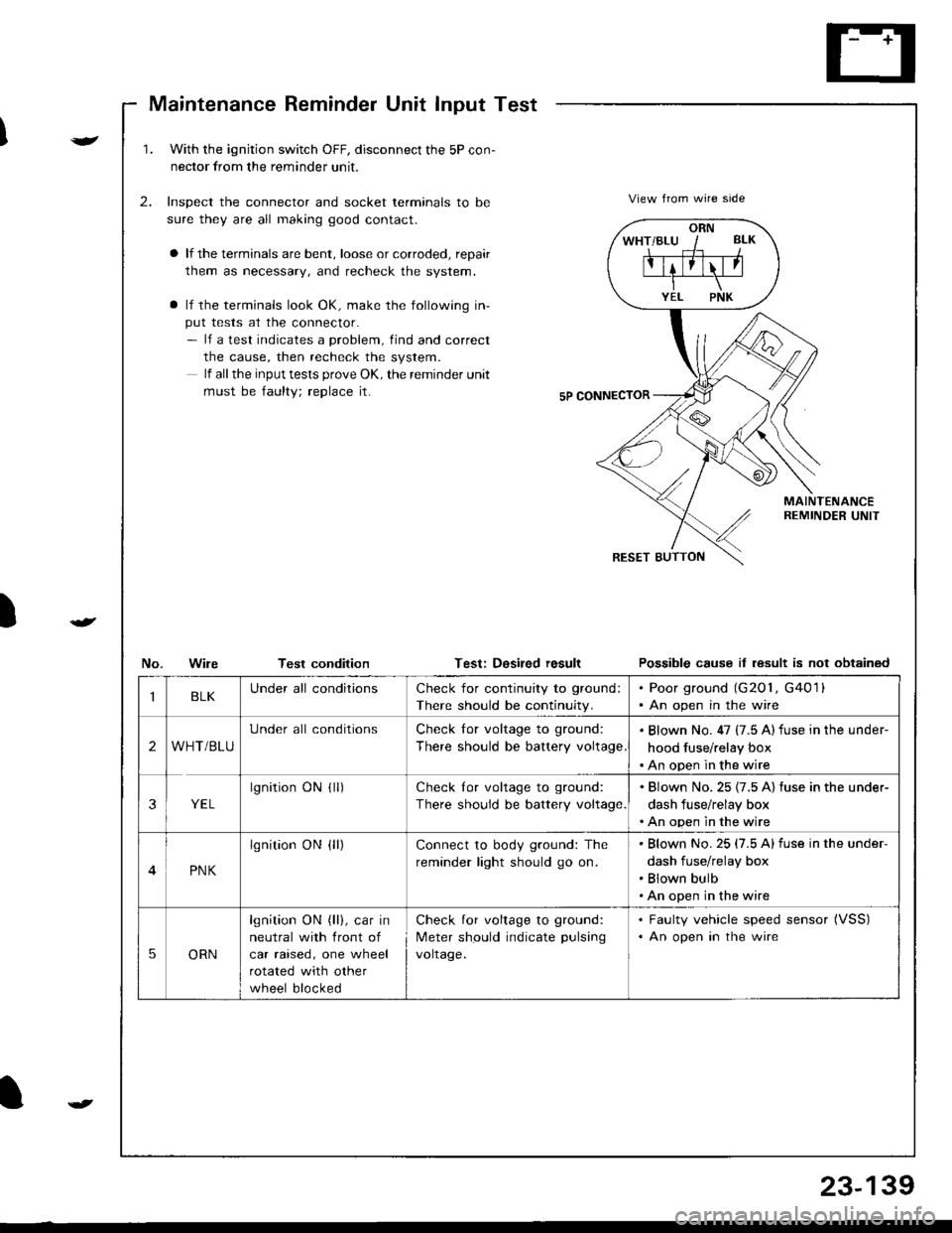
1.With the ignjtion switch OFF, disconnect the 5P con-
nector from the reminder unit.
Inspect the connector and socket terminals to be
sure they are all making good contact.
a lf the terminals are bent, loose or corroded, repair
them as necessary, and recheck the system.
a lf the terminals look OK, make the following in-
put tests at the connector.- lf a test indicates a problem, find and correct
the cause, then recheck the system.
lf all the input tests prove OK, the remind€r unit
must be faulty; replace it.
2.View from wire side
MAINTENANCEREMINDER UNIT
No.WileTest conditionTest: Dosired resultPossible cause it lesult is not obtained
ORN
IBLKUnder all conditionsCheck for continuity to ground:
There should be continuity.
. Poor ground (G201, G4011. An open in the wire
2WHT/BLU
Under all conditionsCheck for voltage to ground:
There should be battery voltage
. Blown No. 47 (7.5 A) fuse in the under-
hood fuse/relay box. An open in the wire
3YEL
lgnitionONflr)Check lor voltage to ground:
There should be battery voltage.
. Blown No.25 {7.5 A) fuse in the under-
dash fuse/relay box. An open in the wire
4PNK
lgnition ON {ll)Connect to body ground: The
reminder light should go on.
Blown No.25 (7.5 Alfuse in the under-
dash fuse/relay box
Blown bulb
An open in the wire
5ORN
lgnition ON (ll), car in
neutral with front of
car raised, one wheel
rotated with other
wheel blocked
Check for voltage to ground:
Meter should indicate pulsang
voltage.
. Faulty vehicle speed sensor (VSS)
. An open in the wire
t
23-139
Page 1204 of 1680
lnterlock System
Circuit Diagram
NOTE: Different wires with the same color have been given a number suflix to distinguish them (for example,cRNA/VHT I and cRNMHT '� are not the same).
WHT/ BLK .-- WHI
cnrruvgr'
+. BRAKE LIGNTS.CSUISE CONTROLUNIT. ABS COIITROL UNIT' ECM
INTEBLOCKCONTROLUNIT
A]'IGEARPOStTIONINOICATOR
v
t,
UNDER-HOOO FUSEi RELAY BOX
N0.41 (100A) N0.42 (404)
YEUBLUcnrivrr '
WHT/BLU
KEYINTERLOCKswtTcH
THBOTTLEPosrT|0N (TP)SENSOR
f7
IRED/BLK
(Cjl :in posiron E t
23-14A
Page 1205 of 1680
){r/
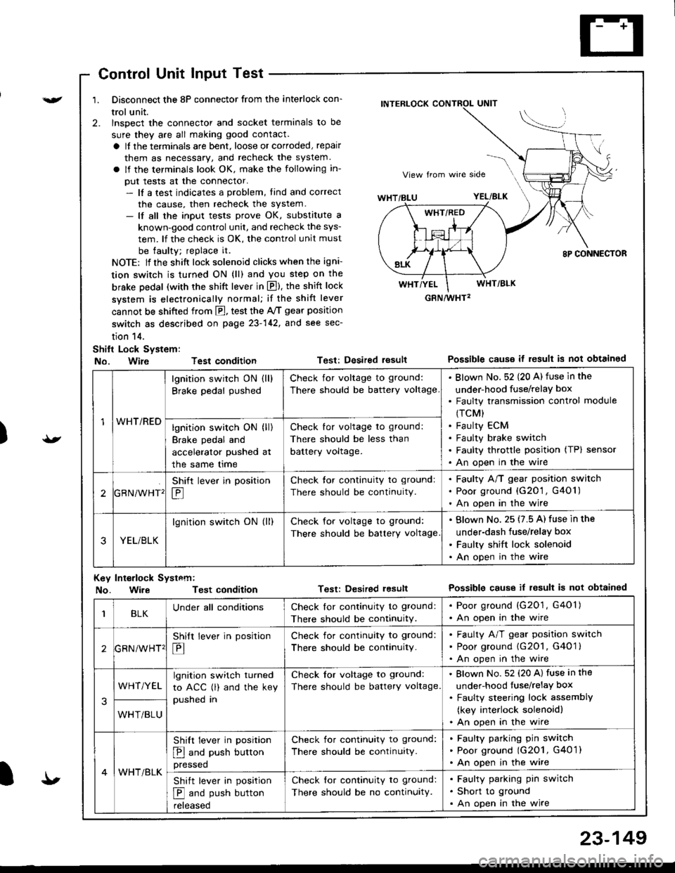
Control Unit Input Test
1. Disconnect the 8P connector from the interlock con-
trol unit.
2. lnspect the connector and socket terminals to be
sure they are all making good contact.
a It the terminals are bent, loose or corroded, repair
them as necessary, and recheck the system.
a lf the terminals look OK, make the following in-
put tests at the connector.- lf a test indicates a problem, tind and correct
the cause, then recheck the system.- lf all the input tests prove OK, substitute a
known-good control unit, and recheck the sys-
tem. lf the check is OK, the control unit must
be faulty; replace it.
NOTE: lf the shift lock solenoid clicks when the igni-
tion switch is turned ON (ll) and you step on the
brske Dedal (with the shift lever in E). the shift lock
system is electronically normal; if the shift lever
cannot be shifted from fl, test the 46 gear position
switch as described on page 23-142, and see sec-
tion 14.
Shift Lock System:
No. Wire Test condition
No. WireTest condition
Test: Desired resultPossible causs it result is not obtained
Test: Dcsired lesultPossible cause it result is not obtainsd
INTERLOCK CONTROL UNIT
GRN/wHT2
1WHT/RED
lgnition switch ON (ll)
Brake pedal pushed
Check for voltage to ground:
There should be battery voltage
Blown No. 52 {20 A) fuse in the
under-hood fuse/relaY box
Faulty transmission control module
(TCM)
Faulty ECM
Faulty brake switch
Faulty throttle position (TP) sensor
An open in the wire
lgnition switch ON (ll)
Brake pedal and
accelerator pushed at
the same me
Check for voltage to ground:
There should be less than
battery voltage.
tGRN/WHT'
Shift lever in position
E
Check tor continuity to ground:
There should be continuity.
Faulty A/T gear position switch
Poor ground {G20'1 , G401)
An open in the wire
3YEL/BLK
lgnition switch ON (ll)Check for voltage to ground:
There should be battery voltage
Blown No. 25 (7.5 A) fuse in the
under-dash fuse/relay box
Faulty shift lock solenoid
An open in the wire
Key Int€rlock Systcm:
BLKUnder all conditionsCheck lor continuity to ground:
There should be continuitY.
. Poor ground (G201, G401). An open in the wire
GRNiWHT'
Shift lever in position
E
Check for continuity to ground:
There should be continuity.
Faulty A/T gear position switch
Poor ground {G2O1, G401 }
An open in the wire
3
WHT/YELlgnition switch turned
to ACC (l) and the key
pushed in
Check tor voltage to ground:
There should be battery voltage.
Blown No. 52 (20 A) fuse in the
under-hood fuse/relaY box
Faulty steering lock assemblY
(key interlock solenoidl
An open in the wireWHT/BLU
4WHT/BLK
Shift lever in position
E and push button
pressed
Check for continuity to ground:
There should be continuity.
Faulty pafking pin switch
Poor ground (G2O1, G4O 1)
An open in the wire
Shift lever in position
E and push button
reteaseo
Check for continuity to ground:
There should be no continuity.
Faulty parking pin switch
Short to ground
An open in the wire
I'
23-149