Page 1088 of 1680

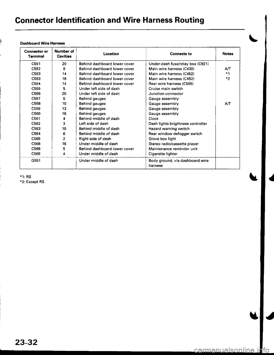
Connector ldentification and Wire Harness Routing
Dsshboard lvirc Harn€ss
Connoctor or
Terminal
Number ol
Cavitie3LocationCoDnects toNotes
c554
L55t'
c561
c562
c563
c564
c565
ucoo
uc06
c569
20
8
14
to
14
20
10
13
16
4
10
6
16
Behind dashboard lower cover
Behind dashboard lower cover
Behind dashboard lower cover
Behind dashboard lower cover
Behind dashboard lower cover
Under left side of dash
Under left side of dash
Behind gauges
Behind gauges
Behind gauges
Behind gauges
Behind middle of dash
Left side of dash
Behind middle of dash
Behind middle of dash
Right side of dash
Under middle of dash
Behind dashboard lower cover
Under middle of dash
Under-dash fuse/relay box (C921)
Main wire harness (C430)
Main wire harness (C452)
Main wire harness (C452)
Rear wire harness (C505)
Cruise main switch
Junction connector
Gauge assembly
Gauge assembly
Gauge assembly
Gauge assembly
Clock
Dash lights brightness controller
Hazard warning switch
Rear window defogger switch
Glove box light
Stereo radio/cassette player
Maintenance reminder unit
Cigarette lighter
At-|-
uc5 |Under middle of dashBody ground, via dashboard wire
narness
*1: RS12: Except RS
23-32
Page 1102 of 1680
Connector ldentification and Wire Harness Routing
Heater Sub-harness A
Connector or Number of-::'- --. - .-' -:-".: -- Location Connects toI etmtnal uavtt|esNotes
C67'1 J 10 Under right side of dash Main wire harness (C4O4)
C672 i 2 Under right side of dash Main wire harness (C4O3)
C673 t, 2 I Under right side ot dash B{ower motor
C674 4 Behind glove box Blower resistor
C675 4 Behind glove box I Recirculation control motor
C676 3 Behind glove box i A/C thermostat
C677 14 Behind middle ol dash Heater sub-harness B {C681)
Connector ol
Terminal
Number of
CavitiesLocationConnects toNotes
c681
c682
c683
c684
14
I
6
14
Behind middle ot dash
Middle of floor
Behind middle ot dash
Behind middle of dash
Heater sub-harness A iC677)
Mode control motor
Heater {an switch
Heater control panel
Heater Sub-ha.ness B
HEATER SUB-HARNESS A
I
C677 C681HEA
23-46
SUB.HARNESS B
I
Page 1103 of 1680
.lI
SRS Main Harness
Connector ol
Terminal
Number of
CavitiesLocationConnects to Notes
c801
cao2
c803
c804
c807
c808
2
3
2
18
2
2
Behind dashboard lower cover
Under left side of dash
Under left side of dash
Middle of tloor
Behind glove box
under le{t side of dash
Underdash fuse/reiay box (C920)
Main wire harness (C427)
Cable reel
SRS unit
Front passenger's airbag assembly
Memory erase signal (MES)
connector
G801Middle ot floorBody ground, via SRS main
harness
I,l-/
SRS MAIN HARNESS
>\-
D
23-47
Page 1116 of 1680
Power Distribution
Circuit ldentification (cont'd)
RED/BLU -
RED/GRN -
REOMHT -
Righl headlighl (High beam)
High beam indicalo. light
Lelt headlighl (High beam)
Righl headlighl (Low beam)
Letl headlighr (Low beam)
Inlegraled conlrol unn
Optional conneclor (Dash lighls)
Inleglaled conlrol unh
(Flsorelay box so*el)
(Flssrelay bot sock€l)
(Fuse/relay box sodet)
COMBINATIONLIGHT SW TCH
lo| | PAsslNGto
BEo/BLK -- Healor conlrol panel hghl- Mgear posrton consote tighl
Cigarcfl 6 lighter/ashtray lightsGauge lighlsAudio unit connsclorR€ar window delogg€r swnch tbhtClockHazard wanlng swilci lighlGlove box lightOash lights bnghhess conlroller
Leit II
I lronlparkifC lighl
FighlJ
h",J'n') '"",.*
l"fn' ) 'nn., '.', 'nnt {r"o"n)
23-60
Letl L.Rgh I rrense Prale lrgnl
Page 1120 of 1680
Ground Distribution
JUNCIIONCONNECTOR
U : Main wrre larness
E : oashboardwire haness
E , B*tr,it" h",n"..
Circuit ldentification (cont'dl
G40l(From page 23-63)
UNDEN.DASIFUSEi RELAYBOX
Turn sbnal/he2ad relay
hlegraled conlrol unil
BLh-Moonlmlleray- MooNool switch
BLK
BLK
8LK
ABS/SRS indicalor lighvci.dril
oash lighls brighhess clitroller
ClockGauges and indicalor lighlsMaiol€nan6 Gmind€a milR6ar window d6logger switch
A-^..'.''..'..- Cqal€nergrnet
l- Glove box lighlr- Ouise conlrol nan sw|ldr
Steleo mdio/cassello playel
G551
23-64
Page 1233 of 1680
License PlateLights
Replacement
GloveBox Light
Test
Jl.Remove the screws and pull out the license plate
lights.
Turn the bulb socket 45o counterclockwise to re-
move it trom the housing.
l.
2.
Remove the glove box and disconnect the 2P con-
nector,
Check tor continuity between the A and B terminals
in each condition according to the table.
BULB(3.4 Wl
Terminal
c""il-------lB
PUSHED {lid closed)
RELEASED {lid open)o-/a---.ov
ciotG401t
23-177
Page 1265 of 1680

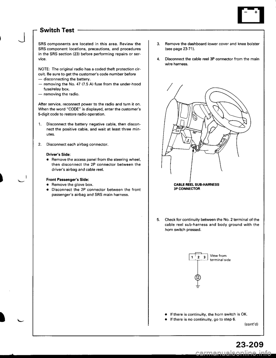
SwitchTest
SRS comDonents are located in this area. Review the
SRS component locations, precautions, and procedures
in the SRS section (23) before performing repairs or ser-
vtce.
NOTE: The original radio has a coded thett protection cir-
cuit. Be sure to get the customer's code number beJore- disconnecting the battery.- removing the No. 47 (7.5 A) fuse from the under-hood
fuse/relay box.- removing the radio.
After service, reconnect Dower to the radio and turn it on.
When the word "CODE" is displayed, enter the customer's
5-digit code to restore radio operation
Disconnect the battery negative cable, then discon-
nect the positive cable, and wait at least three min-
uIes.
Disconnect each airbag connector.
Driver's Side:
a Remove the access panel from the steering wheel,
then disconnect the 2P connector between the
driver's airbag and cable reel.
Front Passenger's Side:
. Remove the glove box,
a Disconnect the 2P connector between the front
passenger's airbag and SRS main harness.
1.
Remove the dashboard lower cover and knee bolster(see page 23-71).
Disconnect the cable reel 3P conneclor from the main
wtre narness.
CABLE REEL SUB.HARNESS3P CONNECTOR
Check for continuitv between the No. 2 terminal of the
cable reel sub-harness and body ground with the
horn switch Dressed.
terminalside
a
It there is continuity, the horn switch is OK.
lf there is no continuity, go to step 6. (cont,d)
r-P r11 2 3l-t-
I
I\-J
)
I
23-209
Page 1266 of 1680
Horn
Switch Test (cont'd)
Remove the driver's airbag assembly (refer to the
SRS sub-section in section 23).
Check for continuity between the No. 2 terminal of
the cable reel sub-harness 3P connector and horn
Dositive terminal.
lf there is no continuity. replace the cable reel.
lf there is continuity, replace the horn switch.
a
a
HORN POSITIVE TERMINAL
23-210
9.
10.
11.
12.
lf all tests prove OK, reinstall the driver's airbag
assembly (re{er to the SRS sub-section in section 23).
Reconnect the driver's airbag connectors, and rein-
stall the access panel on the steering wheel.
Reconnect the front passenger's airbag connector,
and reinstall the glove box.
Connect the battery positive cable, then connect the
negative cable.
Atter installing the airbag assembly, confirm that
- the SRS indicator light should come on for about
six seconds and then go off with the ignition switch
oN 0t).- the horn sounds with the horn button pressed.