Page 3099 of 3342
B5M0122B
3. AIRBAG WARNING LIGHT MODULE (IN
COMBINATION METER) INSPECTION
1) Turn ignition switch“OFF”, disconnect battery ground
cable and then wait at least 20 seconds.
2) Disconnect body harness connector (B31) from connec-
tor (AB1).
B5M0124A
3) Connect battery ground cable and turn ignition switch
“ON”(engine off) to make sure airbag warning light illumi-
nates.
If it does not, replace airbag warning light module�
1.
G5M0312
4. AIRBAG MAIN HARNESS INSPECTION
1) Turn ignition switch“OFF”, disconnect battery ground
cable and then wait at least 20 seconds.
2) Connect body harness connector (B31) and connector
(AB1).
3) Disconnect connectors (AB3) and (AB8) below steering
column.
G5M0313
4) Disconnect connector (AB6) from airbag control mod-
ule.
5) Connect battery ground cable and turn ignition switch
“ON”to make sure airbag warning light illuminates.
39
5-5SUPPLEMENTAL RESTRAINT SYSTEM
5. Diagnostics Chart with Trouble Code
Page 3104 of 3342
 Spray water on vehicle body.
CAUTION:
Do not directly spray water on airbag components.
2) Check passenger compartment for traces of leaking.
NOTE:
If leaks")
G5M0461
2. SHOWERING INSPECTION TO BODY
1) Spray water on vehicle body.
CAUTION:
Do not directly spray water on airbag components.
2) Check passenger compartment for traces of leaking.
NOTE:
If leaks are noted, also check wiring harnesses as water
may leak along them and wet airbag connectors.
3. FUSE No. 16, AIRBAG MAIN HARNESS, AIRBAG
CONTROL MODULE, BODY HARNESS APPEARANCE
AND VIBRATION INSPECTION
1) Conduct appearance inspection on fuse No. 16
5-5 [T5L3].>, airbag main harness ,
airbag control module and body
harness.
NOTE:
Also check connectors, terminals, wiring harness and case
for damage.
2) Conduct vibration inspection on fuse No. 16, airbag
main harness, airbag control module and body harness.
NOTE:
Gently shake each part.
G5M0461
4. SHOWERING INSPECTION TO BODY
1) Spray water on vehicle body.
CAUTION:
Do not directly spray water on each part.
2) Check passenger compartment for traces of leaking.
NOTE:
If leaks are noted, check wiring harnesses as water may
leak along them and get parts wet.
5. WARNING LIGHT ILLUMINATION CHECK
Turn ignition switch“ON”(engine off) and observe airbag
warning light.
Airbag warning light comes“ON”for 8 seconds then goes
out and stays out.
44
5-5SUPPLEMENTAL RESTRAINT SYSTEM
5. Diagnostics Chart with Trouble Code
Page 3112 of 3342
 Airbag warning light comes “ON”.
2) Turn ignition switch to “ON”, (engine “OFF”) and observe airbag wa")
4. Diagnostics Chart for On-board
Diagnostic System
A: BASIC DIAGNOSTICS PROCEDURE
1) Airbag warning light comes “ON”.
2) Turn ignition switch to “ON”, (engine “OFF”) and observe airbag warning light.
3) If airbag warning light stays “ON” after about 7 seconds or remains “OFF”, or comes back “ON” after 30 seconds, this indicates a
current problem. Proceed to step 8).
If airbag warning light comes “ON” for about 7 seconds, then goes out and stays out, this indicates normal system operation at this
time. Check the memory for intermittent problems by performing the procedure outlined in 5-5b [T4B0] “ON-BOARD DIAGNOSTICS”.
Proceed to step 4).
4) If trouble code indicated, proceed to step 5).
If normal code indicated, proceed to step 6).
5) Repair and replacement, proceed to step 7).
6) Repair and replacement, proceed to step 7).
7) Turn ignition switch “ON”, (engine “OFF”) and observe airbag warning light. If airbag warning light stays “ON” after about 7 seconds
or comes back “ON” after 30 seconds, proceed to step 8).
If airbag warning light comes “ON” for about 7 seconds, then goes out and stays out, proceed to step 9).
8) Repair and replacement. Proceed to step 10).
9) Clear memory. Proceed to step 10).
10) END
B5M0115B
B: ON-BOARD DIAGNOSTIC
When the airbag system is in functioning condition, the
airbag warning light will remain on for about 7 seconds and
go out when the ignition switch is set to ON.
If there is any malfunction, the airbag warning light will
either stay on or off continuously. In such cases, perform
on-board diagnostic in accordance with the specified pro-
cedure to determine trouble codes.
1) Turn ignition switch ON (with engine OFF).
2) Connect DIAG. terminal�
1to No. 1 terminal of diagno-
sis connector�
2located below lower cover.
3) Check in accordance with the trouble code indicated by
the AIRBAG warning light, and record the trouble codes.
4) Turn the ignition switch “OFF” and remove the DIAG.
terminal from No.1 terminal of diagnosis connector.
9
5-5bSUPPLEMENTAL RESTRAINT SYSTEM (ELECTRIC SENSOR TYPE)
4. Diagnostics Chart for On-board Diagnostic System
Page 3113 of 3342
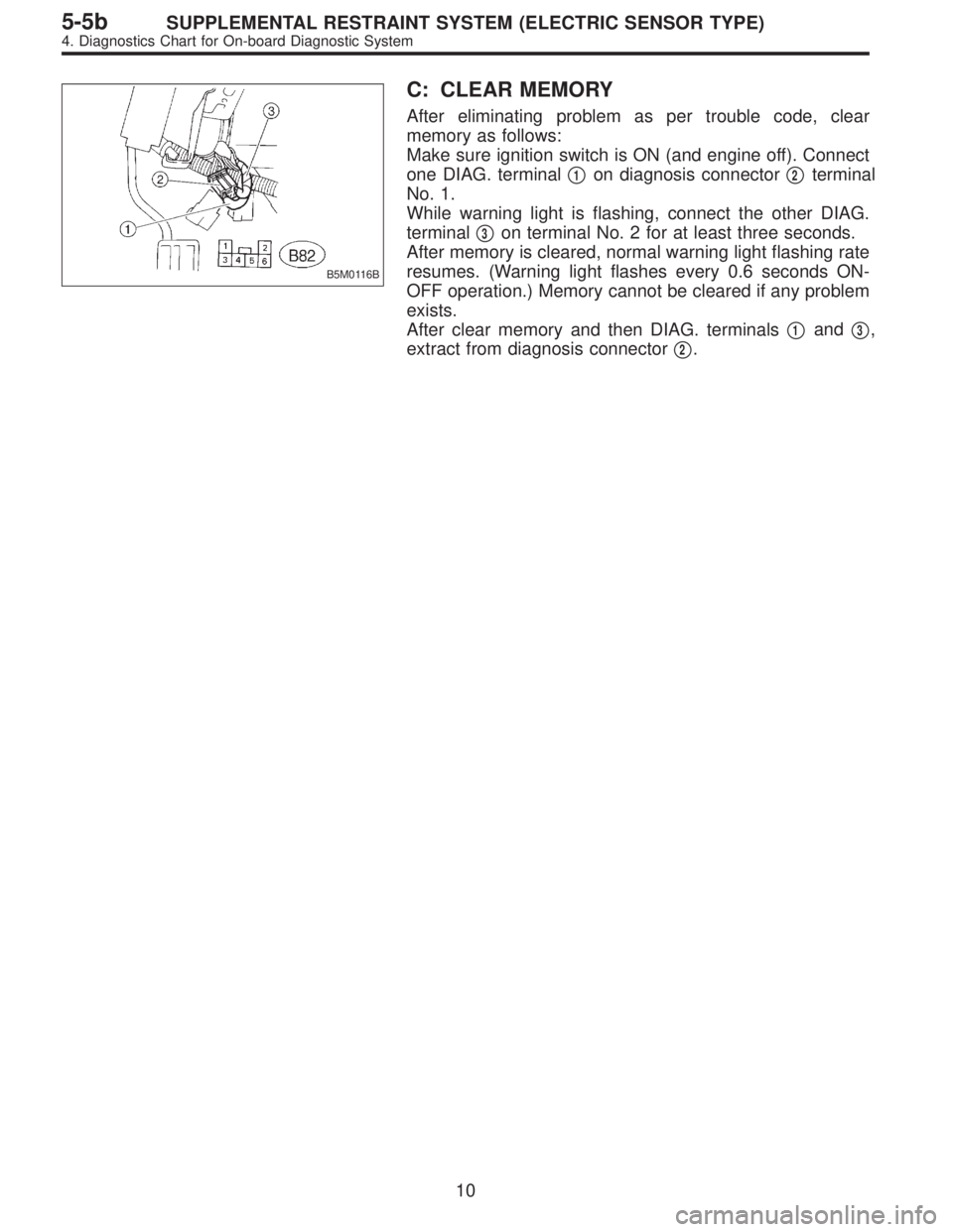
B5M0116B
C: CLEAR MEMORY
After eliminating problem as per trouble code, clear
memory as follows:
Make sure ignition switch is ON (and engine off). Connect
one DIAG. terminal�
1on diagnosis connector�2terminal
No. 1.
While warning light is flashing, connect the other DIAG.
terminal�
3on terminal No. 2 for at least three seconds.
After memory is cleared, normal warning light flashing rate
resumes. (Warning light flashes every 0.6 seconds ON-
OFF operation.) Memory cannot be cleared if any problem
exists.
After clear memory and then DIAG. terminals�
1and�3,
extract from diagnosis connector�
2.
10
5-5bSUPPLEMENTAL RESTRAINT SYSTEM (ELECTRIC SENSOR TYPE)
4. Diagnostics Chart for On-board Diagnostic System
Page 3120 of 3342

B: TROUBLE CODE 11
DIAGNOSIS:
�Airbag control module is faulty.
�Airbag main harness circuit is open.
�Fuse No. 8 is blown.
�Body harness circuit is open.
1. Airbag control module inspection
2. Airbag main harness inspection
3. Fuse No. 8 inspection
CAUTION:
Before performing diagnostics on airbag system, turn
ignition switch“OFF”, disconnect battery ground
cable and then wait at least 20 seconds.
After 20 seconds elapse, remove instrument panel
lower cover, and disconnect (AB3) and (AB8), (AB9)
and (AB10).
G5M0559
1. AIRBAG CONTROL MODULE INSPECTION
1) Disconnect connector (AB6) from airbag control module
and connect it to test harness B2
connector (8B).
2) Connect battery ground cable and turn ignition switch
“ON”. (engine off)
3) Measure voltage across connector (5B) terminal and
chassis ground.
: Connector & terminal
(5B) No. 2 (+)—Chassis ground (�):
Is voltage more than 10 V?
: Replace airbag control module.
: Go to step2.
�
�
17
5-5bSUPPLEMENTAL RESTRAINT SYSTEM (ELECTRIC SENSOR TYPE)
5. Diagnostics Chart with Trouble Code
Page 3129 of 3342

H: TROUBLE CODE 31
DIAGNOSIS:
�Airbag control module is faulty.
�Airbag main harness circuit is open.
�Fuse No. 16 is blown.
�Body harness circuit is open.
1. Airbag control module inspection
2. Airbag main harness inspection
3. Fuse No. 16 inspection
CAUTION:
Before performing diagnostics on airbag system, turn
ignition switch“OFF”, disconnect battery ground
cable and then wait at least 20 seconds.
After 20 seconds elapse, remove instrument panel
lower cover, and disconnect (AB3) and (AB8), (AB9)
and (AB10).
G5M0559
1. AIRBAG CONTROL MODULE INSPECTION
1) Disconnect connector (AB6) from airbag control module
, and connect it to test harness B2
connector (8B).
2) Connect battery ground cable and turn ignition switch
“ON”(engine off).
3) Measure voltage across connector (5B) terminal and
chassis ground.
: Connector & terminal
(5B) No. 5 (+)—Chassis ground (�):
Is voltage more than 10 V?
: Replace airbag control module.
: Go to step2.
�
�
26
5-5bSUPPLEMENTAL RESTRAINT SYSTEM (ELECTRIC SENSOR TYPE)
5. Diagnostics Chart with Trouble Code
Page 3132 of 3342
 is shorted to
power supply.
�Airbag module harness (Passenger) is shorted to power
supply.
�Airbag control module is faulty.
1. A")
J: TROUBLE CODE 34
DIAGNOSIS:
�Airbag main harness circuit (Passenger) is shorted to
power supply.
�Airbag module harness (Passenger) is shorted to power
supply.
�Airbag control module is faulty.
1. Airbag main harness inspection
CAUTION:
Before performing diagnostics on airbag system, turn
ignition switch“OFF”, disconnect battery ground ter-
minal and then wait at least 20 seconds.
After 20 seconds elapse, remove instrument panel
lower cover, and disconnect (AB3) and (AB8), (AB9)
and (AB10).
G5M0559
1. AIRBAG MAIN HARNESS INSPECTION
1) Disconnect connector (AB6) from airbag control module
, and connect it to test harness B2
connector (8B).
2) Connect battery ground cable and turn ignition switch
“ON”(engine off).
3) Measure voltage across each test harness B2 connec-
tor (5B) terminal and chassis ground.
: Connector & terminal
(5B) No. 6 (+)—Chassis ground (�):
Is voltage less than 1 V?
: Go to next.
: Replace airbag main harness.
: Connector & terminal
(5B) No. 7 (+)—Chassis ground (�):
Is voltage less than 1 V?
: Replace airbag control module.
: Replace airbag main harness.
29
5-5bSUPPLEMENTAL RESTRAINT SYSTEM (ELECTRIC SENSOR TYPE)
5. Diagnostics Chart with Trouble Code
Page 3135 of 3342
 is shorted to power
supply.
�Airbag module harness (Driver) is shorted to power sup-
ply.
�Roll connector is shorted to power supply")
M: TROUBLE CODE 43
DIAGNOSIS:
�Airbag main harness circuit (Driver) is shorted to power
supply.
�Airbag module harness (Driver) is shorted to power sup-
ply.
�Roll connector is shorted to power supply.
�Airbag control module is faulty.
1. Airbag main harness inspection
CAUTION:
Before performing diagnostics on airbag system, turn
ignition switch“OFF”, disconnect battery ground ter-
minal and then wait at least 20 seconds.
After 20 seconds elapse, remove instrument panel
lower cover, and disconnect (AB3) and (AB8), (AB9)
and (AB10).
G5M0559
1. AIRBAG MAIN HARNESS INSPECTION
1) Disconnect connector (AB6) from airbag control module
, and connect it to test harness B2
connector (8B).
2) Connect battery ground cable and turn ignition switch
“ON”(engine off).
3) Measure voltage across each test harness B2 connec-
tor (5B) terminal and chassis ground.
: Connector & terminal
(5B) No. 1 (+)—Chassis ground (�):
Is voltage less than 1 V?
: Go to next.
: Replace airbag main harness.
: Connector & terminal
(5B) No. 14 (+)—Chassis ground (�):
Is voltage less than 1 V?
: Replace airbag control module.
: Replace airbag main harness.
32
5-5bSUPPLEMENTAL RESTRAINT SYSTEM (ELECTRIC SENSOR TYPE)
5. Diagnostics Chart with Trouble Code
 INSPECTION
1) Turn ignition switch“OFF”, disconnect battery ground
cable and then wait at least 20 seconds.
2) Disconnect body harnes")