Page 1897 of 3342
B2M0482
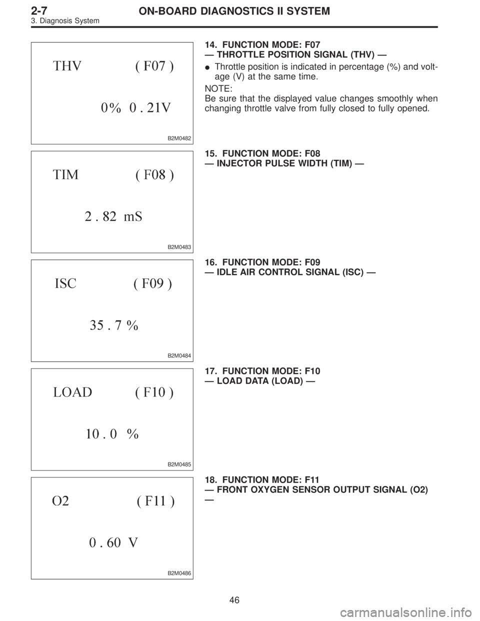
14. FUNCTION MODE: F07
—THROTTLE POSITION SIGNAL (THV)—
�Throttle position is indicated in percentage (%) and volt-
age (V) at the same time.
NOTE:
Be sure that the displayed value changes smoothly when
changing throttle valve from fully closed to fully opened.
B2M0483
15. FUNCTION MODE: F08
—INJECTOR PULSE WIDTH (TIM)—
B2M0484
16. FUNCTION MODE: F09
—IDLE AIR CONTROL SIGNAL (ISC)—
B2M0485
17. FUNCTION MODE: F10
—LOAD DATA (LOAD)—
B2M0486
18. FUNCTION MODE: F11
—FRONT OXYGEN SENSOR OUTPUT SIGNAL (O2)
—
46
2-7ON-BOARD DIAGNOSTICS II SYSTEM
3. Diagnosis System
Page 2122 of 3342

1) Turn ignition switch to ON. (Engine OFF)
2) Measure voltage between ECM connector and chassis
ground.
: Co")
H2M1414B
10AZ3CHECK INPUT SIGNAL FOR ECM.
(USING VOLTAGE METER AND SUBARU
SELECT MONITOR.)
1) Turn ignition switch to ON. (Engine OFF)
2) Measure voltage between ECM connector and chassis
ground.
: Connector & terminal
(B84) No. 27 (+)—Chassis ground (�):
Is the voltage less than 0.12 V?
: Go to step10AZ4.
: Go to next.
H2M1327
: Does the value change less than 0.12 V by
shaking harness and connector of ECM
while monitoring the value with Subaru
Select Monitor?
�Subaru Select Monitor
Designate mode using function key.
Function mode: F45
�F45: Fuel level sensor output signal is indicated.
: Repair poor contact in ECM connector.
: Even if MIL lights up, the circuit has returned to a
normal condition at this time. A temporary poor
contact of the connector may be the cause.
NOTE:
In this case, repair the following:
�Poor contact in fuel pump connector
�Poor contact in combination meter connector
�Poor contact in ECM connector
�Poor contact in coupling connector (i3, B99, B22, B98
and R57)
G2M0340
10AZ4CHECK HARNESS BETWEEN ECM, COM-
BINATION METER AND FUEL PUMP
CONNECTOR.
1) Turn ignition switch to OFF.
2) Remove fuel pump access hole lid located on the right
rear of trunk compartment floor (Sedan) or luggage com-
partment floor (Wagon).
271
2-7ON-BOARD DIAGNOSTICS II SYSTEM
10. Diagnostic Chart with Trouble Code for LHD Vehicles
Page 2257 of 3342
 Turn ignition switch to OFF.
2) Connect test mode connector at the lower portion of
instrument panel (on the driver’s side), to the side of the
center")
OBD0736A
10CW1
CHECK OUTPUT SIGNAL FROM ECM.
1) Turn ignition switch to OFF.
2) Connect test mode connector at the lower portion of
instrument panel (on the driver’s side), to the side of the
center console box.
3) Turn ignition switch to ON.
B2M0608A
4) Measure voltage between ECM and chassis ground.
: Connector & terminal
(B84) No. 74 (+)—Chassis ground:
Does voltage change between 0 and 10
volts?
NOTE:
Radiator fan relay operation check can be executed using
Subaru Select Monitor (Function mode: FD03). For
procedure, refer to“COMPULSORY VALVE OPERATION
CHECK MODE”.
: Go to step10CW2.
: Even if MIL lights up, the circuit has returned to a
normal condition at this time. In this case, repair
poor contact in ECM connector.
B2M0611A
10CW2CHECK SHORT CIRCUIT IN RADIATOR
FAN RELAY 1 CONTROL CIRCUIT.
1) Turn ignition switch to OFF.
2) Remove main fan relay 1 and sub fan relay 1. (with A/C
models)
Remove main fan relay. (without A/C models)
3) Disconnect test mode connector.
4) Turn ignition switch to ON.
5) Measure voltage between ECM and chassis ground.
: Connector & terminal
(B84) No. 74 (+)—Chassis ground (�):
Is the voltage more than 10 V?
: Repair battery short circuit in radiator fan relay 1
control circuit. After repair, replace ECM.
: Go to next.
: Is there poor contact in ECM connector?
: Repair poor contact in ECM connector.
: Replace ECM.
406
2-7ON-BOARD DIAGNOSTICS II SYSTEM
10. Diagnostic Chart with Trouble Code for LHD Vehicles
Page 2269 of 3342
B2M0615A
: Connector & terminal
(B84) No. 80 (+)—Chassis ground (�):
Does the voltage change from1Vto4V
while monitoring the value with voltage
meter?
: Even if MIL lights up, the circuit has returned to a
normal condition at this time.
NOTE:
In this case, repair the following:
�Poor contact in ECM connector
�Poor contact in TCM connector
: Contact with SOA service.
NOTE:
Inspection by DTM is required, because probable cause is
deterioration of multiple parts.
B2M1164A
10DB4CHECK HARNESS BETWEEN ECM AND
TCM CONNECTOR.
Measure voltage between TCM and chassis ground.
: Connector & terminal
(B55) No. 11 (+)—Chassis ground (�):
Is the voltage more than 4 V?
: Go to next.
: Repair open circuit in harness between ECM and
TCM connector.
: Is there poor contact in TCM connector?
: Repair poor contact in TCM connector.
: Check TCM power supply line and grounding line.
418
2-7ON-BOARD DIAGNOSTICS II SYSTEM
10. Diagnostic Chart with Trouble Code for LHD Vehicles
Page 2339 of 3342

1) Turn ignition switch to ON. (Engine OFF)
2) Measure voltage between ECM connector and chassis
ground.
: Co")
H2M1414B
11AZ3CHECK INPUT SIGNAL FOR ECM.
(USING VOLTAGE METER AND SUBARU
SELECT MONITOR.)
1) Turn ignition switch to ON. (Engine OFF)
2) Measure voltage between ECM connector and chassis
ground.
: Connector & terminal
(B84) No. 27 (+)—Chassis ground (�):
Is the voltage less than 0.12 V?
: Go to step11AZ4.
: Go to next.
H2M1327
: Does the value change less than 0.12 V by
shaking harness and connector of ECM
while monitoring the value with Subaru
Select Monitor?
�Subaru Select Monitor
Designate mode using function key.
Function mode: F45
�F45: Fuel level sensor output signal is indicated.
: Repair poor contact in ECM connector.
: Even if MIL lights up, the circuit has returned to a
normal condition at this time. A temporary poor
contact of the connector may be the cause.
NOTE:
In this case, repair the following:
�Poor contact in fuel pump connector
�Poor contact in combination meter connector
�Poor contact in ECM connector
�Poor contact in coupling connector (i3, B22, B97 and
R57)
488
2-7ON-BOARD DIAGNOSTICS II SYSTEM
11. Diagnostic Chart with Trouble Code for RHD Vehicles
 No. 80 (+)—Chassis ground (�):
Does the voltage change from1Vto4V
while monitoring the value with voltage
meter?
: Even if MIL lights up, the circuit has return")