1997 SSANGYONG KORANDO roof
[x] Cancel search: roofPage 1811 of 2053
FRAME AND UNDERBODY 9N-9
SSANGYONG MY2002
GENERAL DESCRIPTION AND SYSTEM OPERATION
GENERAL BODY CONSTRUCTION
This vehicle is constructed with a unitized body which
in-corporates integral front and rear frame side rails.
The front suspension lower control arms are bolted to
and retained by supports, one each on the right and
left sides. The front suspension lower control arm
supports are attached to the underbody with three bolts
at two locations. The engine is bolted to the integral
front side rails. The suspension strut towers must be
dimensionally correct in relation to the remainder of
the underbody in order to maintain specified
suspension strut and caster/camber angles.
Since the individual underbody parts contribute directly
to the overall strength of the body, it is essential to
observe proper welding techniques during servicerepair operations. The underbody parts should be
properly sealed and rustproofed whenever body repair
operations destroy or damage the original sealing and
rustproofing. When rustproofing critical underbody
parts, use a good-quality type of air-dry primer, such
as a corrosion-resistant chromate or an equivalent
material. Combination-type primer/surfacers are not
recommended.
ENGINE UNDER COVERS
The engine under covers are molded pieces of plastic
that serve as shields for the underside of the engine.
The covers help protect the engine from small rocks,
gravel and other objects that would otherwise come
into contact with the engine during normal driving
conditions.
Page 1812 of 2053
SSANGYONG MY2002
9O-6 BUMPERS AND FASCIAS
KAA9O070
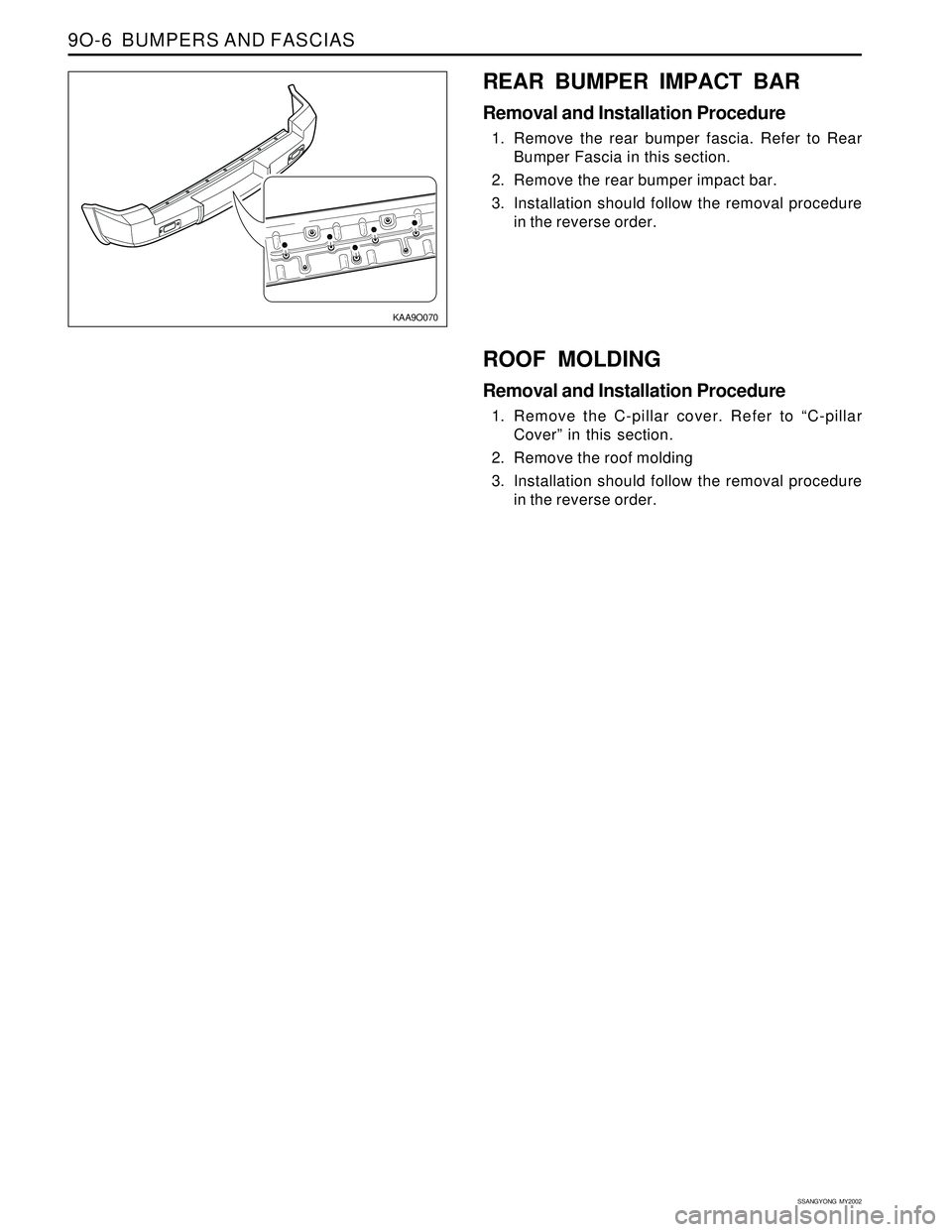
REAR BUMPER IMPACT BAR
Removal and Installation Procedure
1. Remove the rear bumper fascia. Refer to Rear
Bumper Fascia in this section.
2. Remove the rear bumper impact bar.
3. Installation should follow the removal procedure
in the reverse order.
ROOF MOLDING
Removal and Installation Procedure
1. Remove the C-pillar cover. Refer to “C-pillar
Cover” in this section.
2. Remove the roof molding
3. Installation should follow the removal procedure
in the reverse order.
Page 1813 of 2053
Description and Operation..................................9O-2
Bumpers............................................................9O-2
Components Locator ...........................................9O-3
Bumpers and Fascias .........................................9O-3
Repair Instructions...............................................9O-4
On-Vehicle Service Unit Repair...............................9O-4
Front Bumper Fascia ...........................................9O-4
SECTION 9O
BUMPERS AND FASCIAS
CAUTION: Disconnect the negative battery cable before removing or installing any electrical unit or when a
tool or equipment could easily come in contact with exposed electrical terminals. Disconnecting this cable
will help prevent personal injury and damage to the vehicle. The ignition must also be in LOCK unless
otherwise noted.
TABLE OF CONTENTS
Rear Bumper Fascia...........................................9O-5
Front Bumper Impact Bar....................................9O-5
Rear Bumper Impact Bar....................................9O-6
Roof Molding......................................................9O-6
Specifications......................................................9O-7
Fastener Tightening Specifications......................9O-7
Page 1832 of 2053
SECTION 9Q
ROOF
CAUTION: Disconnect the negative battery cable before removing or installing any electrical unit or when a
tool or equipment could easily come in contact with exposed electrical terminals. Disconnecting this cable
will help prevent personal injury and damage to the vehicle. The ignition must also be in LOCK unless
otherwise noted.
TABLE OF CONTENTS
Description and Operation..................................9Q-2
Sunvisors ...........................................................9Q-2
Cat Hook............................................................9Q-2
Components Locator ...........................................9Q-3
Roof...................................................................9Q-3Unit Repair...........................................................9Q-4
Formed Headliner...............................................9Q-4
Sun Visors..........................................................9Q-4
Page 1833 of 2053
SSANGYONG MY2002
9Q-2 ROOF
DESCRIPTION AND OPERATION
SUNVISORS
The sun visors swing down in order to block out glare.
They also swing to the side when they are released
from the support. Each sun visor has a vanity mirror.
CAT HOOK
The coat hook is fastened to the headliner above the
left hand rear passenger’s seat.
Page 1834 of 2053
ROOF 9Q-3
SSANGYONG MY2002
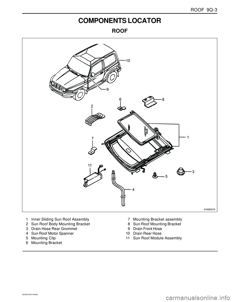
COMPONENTS LOCATOR
ROOF
KAA9Q010
1 Inner Sliding Sun Roof Assembly
2 Sun Roof Body Mounting Bracket
3 Drain Hose Rear Grommet
4 Sun Roof Motor Spanner
5 Mounting Clip
6 Mounting Bracket7 Mounting Bracket assembly
8 Sun Roof Mounting Bracket
9 Drain Front Hose
10 Drain Rear Hose
11 Sun Roof Module Assembly
Page 1835 of 2053
SSANGYONG MY2002
9Q-4 ROOF
KAA9Q030
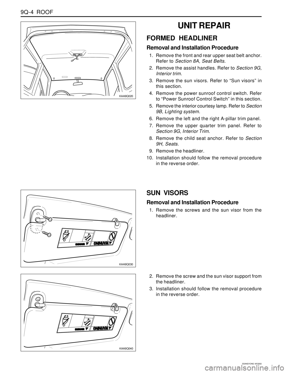
SUN VISORS
Removal and Installation Procedure
1. Remove the screws and the sun visor from the
headliner.
KAA9Q020
UNIT REPAIR
FORMED HEADLINER
Removal and Installation Procedure
1. Remove the front and rear upper seat belt anchor.
Refer to Section 8A, Seat Belts.
2. Remove the assist handles. Refer to Section 9G,
Interior trim.
3. Remove the sun visors. Refer to “Sun visors” in
this section.
4. Remove the power sunroof control switch. Refer
to “Power Sunroof Control Switch” in this section.
5. Remove the interior courtesy lamp. Refer to Section
9B, Lighting system.
6. Remove the left and the right A-pillar trim panel.
7. Remove the upper quarter trim panel. Refer to
Section 9G, Interior Trim.
8. Remove the child seat anchor. Refer to Section
9H, Seats.
9. Remove the headliner.
10. Installation should follow the removal procedure
in the reverse order.
2. Remove the screw and the sun visor support from
the headliner.
3. Installation should follow the removal procedure
in the reverse order.
KAA9Q040
Page 1868 of 2053
2-4 2-4 2-4 2-4
2-4
ELECTRICAL WIRING DIAGRAMS ELECTRICAL WIRING DIAGRAMSELECTRICAL WIRING DIAGRAMS ELECTRICAL WIRING DIAGRAMS
ELECTRICAL WIRING DIAGRAMS
Engine Room Fuse Box - W/H Main
Engine Room Fuse Box - W/H Main
Engine Room Fuse Box - W/H Main
Engine Room FuseBox - W/H Main
Engine Room Fuse Box - W/H Engine Room
Engine Room Fuse Box - W/H Engine Room
Engine Room Fuse Box - W/H Engine Room
Engine Room Fuse Box - W/H Engine Room
W/H Engine Room - W/H Pre - Heating
W/H Engine Room - W/H Alternator
W/H Engine Room - W/H Alternator
W/H Engine Room - W/H Wheel G. sensor
W/H Engine Room - W/H Main
W/H Engine Room - W/H Main
W/H Engine Control - W/H ECM Main
W/H Engine Control - W/H ECM Main
W/H Main - W/H Fuel Cut Solenoid
W/H Main - W/H Roof
W/H Main - W/H Air Bag
W/H Main - W/H Air Bag
W/H Main - W/H SDM
W/H Main - W/H Air Conditioner
W/H Main - W/H ECM Main
W/H Main - W/H Transmission
W/H Main - W/H Transmission
W/H Main - W/H Transmission
W/H Main - W/H Fuel Pump
W/H Main - W/H Fuel Pump
W/H Main - W/H Fuel Pump
W/H Main - W/H Seat Heater
W/H Main - W/H Main
W/H Main - W/H FRT LH Door
W/H FRT LH Door - W/H Speaker
W/H Main - W/H FRT RH Door
W/H FRT RH Door - W/H Speaker
G201W/H Main Upper Front Left Leg Room
G202W/H Main Upper Front Left Leg Room
G203W/H Main Left Upper Center Facia
G204W/H Main Left Lower Center Facia
G205W/H Main Center "A" Pillar Front Right
G301W/H Main Below Front Left seat
G302W/H Main Below Center Console
G303W/H Main Below Front Right seat
G401W/H Main Inside Lower Trim Rear Left Quater
Engine Room Fuse Box
Engine Room Fuse Box
Engine Room Fuse Box
Engine Room Fuse Box
Engine Room Fuse Box
Engine Room Fuse Box
Engine Room Fuse Box
Engine Room Fuse Box
Bhind Battery
Below Air Cleaner
Below Air Cleaner
Upper Front Right Control Arm
Next to Hydraulic Unit
Next to Hydraulic Unit
Behind Hydraulic Unit
Behind Hydraulic Unit
Next to Engine Room Fuse Box
Inside Left Cluster
Above FRT LH Seat Under Cover
Above FRT LH Seat Under Cover
Lower Rear Center Facia
Upper Evaporator
Lower "A" Piller(Upper ECM)
Upper Transfer Case
Upper Transfer Case
Upper Transfer Case
Upper Transfer Case
Upper Transfer Case
Upper Transfer Case
Below FRT LH Seat
Below Center Console
Upper Fuse Box
(Passenger Room)
Inside FRT LH Door Trim
Behind Front Right Panel
Inside FRT RH Door Trim
2. 2.2. 2.
2.
CONNECT CONNECTCONNECT CONNECT
CONNECT
OR, OR,OR, OR,
OR,
GR GR GR GR
GR
OUND AND SPLICE PA OUND AND SPLICE PAOUND AND SPLICE PA OUND AND SPLICE PA
OUND AND SPLICE PA
CK INFORMA CK INFORMACK INFORMA CK INFORMA
CK INFORMA
TION TIONTION TION
TION1) 1)1) 1)
1)
CONNECTOR CONNECTORCONNECTOR CONNECTOR
CONNECTORConnector Number Connector NumberConnector Number Connector Number
Connector Number
(Pin Number, Color) (Pin Number, Color)(Pin Number, Color) (Pin Number, Color)
(Pin Number, Color)Connecting Connecting Connecting Connecting
Connecting
Wiring Harness Wiring HarnessWiring Harness Wiring Harness
Wiring Harness
Connector Position Connector PositionConnector Position Connector Position
Connector Position
C101 (19Pin, White)
C102 (4Pin, Colorless)
C103 (22Pin, White)
C104 (8Pin, Colorless)
C105 (10Pin, White)
C106 (3Pin, Black)
C107 (20Pin, White)
C108 (6Pin, Colorless)
C109 (1Pin, Black)
C110 (2Pin, Black)
C110 (4Pin, Black)
C111 (3Pin, Black)
C112 (6Pin, Black)
C113 (12Pin, Black)
C114 (6Pin, Gray)
C115 (40Pin, Black)
C116 (3Pin, Black)
C201 (8Pin, White)
C202 (4Pin, White)
C203 (2Pin, Black)
C204 (4Pin, Colorless)
C205 (17Pin, White)
C206 (6Pin, Black)
C301 (2Pin, Black)
C301 (16Pin, Black)
C302 (10Pin, Black)
C303 (3Pin, Black)
C303 (4Pin, Black)
C303 (6Pin, Black)
C304 (10Pin, White)
C305 (14Pin, White)
C351 (22Pin, White)
C352 (2Pin, Black)
C361 (22Pin, Blue)
C362 (2Pin, Black)
2) 2)2) 2)
2)
SPLICE PACK SPLICE PACKSPLICE PACK SPLICE PACK
SPLICE PACK
S201
S202
S203
S204
S205Splice Pack Position Splice Pack PositionSplice Pack Position Splice Pack Position
Splice Pack Position Wiring WiringWiring Wiring
Wiring
Harness HarnessHarness Harness
Harness Color ColorColor Color
Color Splice Pack Splice PackSplice Pack Splice Pack
Splice Pack
Number NumberNumber Number
Number
Colorless
Black
Colorless
Colorless
ColorlessW/H Main
W/H Main
W/H Main
W/H Main
W/H MainUpper Fuse Box(Passenger Room)
Behind Cluster
Behind 4WD Switch
Behind Audio
Behind Front Right Kick Panel
Remark RemarkRemark Remark
Remark
Diesel only
Gasoline
Diesel
Gasoline
Gasoline
Diesel
Gasoline
Manual T/M
Automatic T/M
Diesel
Diesel
Gasoline
GSL : EURO IIIBehind Left Tail Lamp
Behind Left Tail Lamp
Inside Rear Bumper
Inside Tail Gate
Connector Number Connector NumberConnector Number Connector Number
Connector Number
(Pin Number, Color) (Pin Number, Color)(Pin Number, Color) (Pin Number, Color)
(Pin Number, Color)Connecting Connecting Connecting Connecting
Connecting
Wiring Harness Wiring HarnessWiring Harness Wiring Harness
Wiring Harness
Connector Position Connector PositionConnector Position Connector Position
Connector Position
C401 (2Pin, Black)
C402 (12Pin, Black)
C403 (3Pin, Black)
C404 (2Pin, Black)W/H Tail Gate - W/H Main
W/H Tail Gate - W/H Main
W/H Rear Bumper - W/H Main
W/H Tail Gate - W/H HMSL
Remark RemarkRemark Remark
Remark
3) 3)3) 3)
3)
GROUND GROUNDGROUND GROUND
GROUND
G101
G102
G103Ground Position Ground PositionGround Position Ground Position
Ground Position
Wiring Harness Wiring HarnessWiring Harness Wiring Harness
Wiring Harness Number NumberNumber Number
Number
Ground GroundGround Ground
Ground
W/H Engine Room
Battery
W/H Engine RoomLeft Fender Next to Battery
Center Engine Block
Right Fender Engine Room
Pin PinPin Pin
Pin
Number NumberNumber Number
Number
8
20
14
14
8