1997 SSANGYONG KORANDO glow
[x] Cancel search: glowPage 753 of 2053

D AEW OO M Y_2000
SECTION 1E3
OM600 ENGINE ELECTRICAL
Caution: Disconnect the negative battery cable before removing or installing any electrical unit or when a
tool or equipment could easily come in contact with exposed electrical terminals. Disconnecting this cable
will help prevent personal injury and damage to the vehicle. The ignition must also be in LOCK unless other -
wise noted.
TABLE OF CONTENTS
Specifications 1E3 -- 1............................
General Specifications 1E3-- 1....................
Maintenance and Repair 1E3 -- 2...................
On-- Vehicle Service 1E3-- 2.........................Glow Plug 1E3-- 2...............................
Generator 1E3-- 6...............................
Starter Motor 1E3-- 8............................
SPECIFICATIONS
GENERAL SPECIFICATIONS
ApplicationDescription
Generator12V -- 75A
Starter12V -- 2.2kW
Glow Plug11. 5 V
Page 924 of 2053

SSAMGYONG MY2002
4A-4 HYDRAULIC BRAKES
KAA4A010
BRAKE WARNING LAMP CIRCUIT DESCRIPTION
Diagnostic Aids
The BRAKE lamp glows brightly when the ignition is
ON and either the parking brake lever switch or the
brake fluid level switch is closed.
If neither switch is closed, the BRAKE lamp receives
a ground through the generator, and it glows dimly
when the ignition is ON and the engine is off. When
the engine starts, the generator creates voltage. With
voltage on both sides of the lamp, the lamp turns off.
Test Description
The numbers below refer to steps in the diagnostic
table.
1. This step begins the test sequence for a BRAKE
warning lamp that stays on when the engine is run-
ning.
2. This step begins the test sequence for a BRAKE
warning lamp that never turns on.
Page 1089 of 2053
SSANGYONG MY2002
4G-2 PARKING BRAKE
DESCRIPTION AND OPERATION
BRAKE CALIPER
This braking system uses a BRAKE warning light lo-
cated in the instrument panel cluster.
The following conditions will activate the BRAKE lamp:
•The parking brake is applied when the ignition is
ON. The lamp will turn off when the parking brake
is released.
The fluid level is below the minimum mark in the
master cylinder reservoir. The lamp will turn off when
the fluid level is above the minimum.
As a test of the lamp circuit, the BRAKE lamp will
glow dimly when the ignition is ON, even if the
parking brake is off and fluid level is above the
minimum. The lamp will turn off when the engine is
started. When the brake is firmly applied, the parking
brake should hold the vehicle with ample pedal
travel remaining.
Check for frayed cables, rust, etc. or any condition
that may inhibit present (or future) free movement of
the parking brake lever assembly.
Page 1092 of 2053
PARKING BRAKE 4G-5
SSANGYONG MY2002
KAA4G040
KAA4G050
KAA4G060
KAA4G070
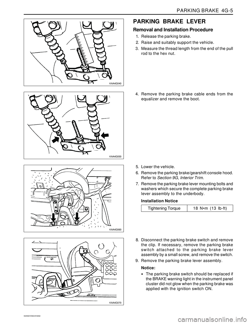
PARKING BRAKE LEVER
Removal and Installation Procedure
1. Release the parking brake.
2. Raise and suitably support the vehicle.
3. Measure the thread length from the end of the pull
rod to the hex nut.
5. Lower the vehicle.
6. Remove the parking brake/gearshift console hood.
Refer to Section 9G, Interior Trim.
7. Remove the parking brake lever mounting bolts and
washers which secure the complete parking brake
lever assembly to the underbody.
Installation Notice
8. Disconnect the parking brake switch and remove
the clip. If necessary, remove the parking brake
switch attached to the parking brake lever
assembly by a small screw, and remove the switch.
9. Remove the parking brake lever assembly.
Notice:
The parking brake switch should be replaced if
the BRAKE warning light in the instrument panel
cluster did not glow when the parking brake was
applied with the ignition switch ON.
Tightening Torque 18 Nm (13 lb-ft) 4. Remove the parking brake cable ends from the
equalizer and remove the boot.
Page 1672 of 2053
BODY WIRING SYSTEM 9A-21
SSANGYONG MY2002
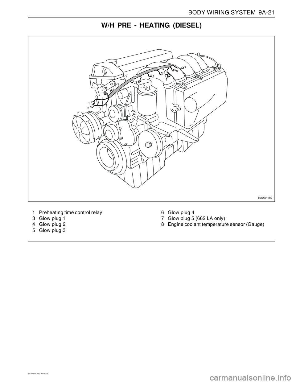
W/H PRE - HEATING (DIESEL)
1 Preheating time control relay
3 Glow plug 1
4 Glow plug 2
5 Glow plug 36 Glow plug 4
7 Glow plug 5 (662 LA only)
8 Engine coolant temperature sensor (Gauge)
KAA9A160
Page 1676 of 2053
SSANGYONG MY2002
9B-2 LIGHTING SYSTEM
DESCRIPTION AND OPERATION
HEAD LAMPS - ON REMINDER
When the headlamp switch is in the headlamps-on or
parkinglamps-on positions, voltage is applied to the
chime module. With the headlamp switch on and the
driver’s side door open, the module loses voltage. The
module senses this change. If voltage is still available,
it is applied to sound the chime. The chime can be
turned off by turning the headlamp switch off or closing
the driver’s side door. To replace the chime module,
refer to Section 9E, Instrumentation / Driver Information.
HEAD LAMPS
The headlamps are controlled by the multifunction lever
on the left side of the steering column. They will come
on with the ignition switch in on position. Turning the
headlamp switch to the first position turns on the
parking lamps, the license plate lamps, and the
instrument panel illumination. Turning the switch to the
second position turns on all of the previous lamps and
the headlamps. Turning the switch off turns off all the
lamps.
The headlamps high beam and low beams are also
controlled by this lever. When the headlamps are on,
pushing the lever away from the driver until the switch
clicks changes the lamp from low beam to high beam.
An indicator lamp on the instrument cluster assembly
will come on when the high beam headlamps are on.
To return the headlamps to low beams, pull the lever
toward the driver.
The headlamps must be aimed for proper illumination
of the road. Headlamp aim should be checked
whenever a new headlamp assembly is installed or
when service or repairs to the front end may have
disturbed the headlamp assembly or its mountings.
DAYTIME RUNNING LAMPS
The daytime running lamps (DRL) will illuminate under
the following conditions:
The ignition is ON.
The light switch is OFF.
The parking brake is released.
When the head lamps are on, the DRL will turn off.
To turn the DRL off when idling, apply the parking
brake.
PARKING AND TURN SIGNAL
LAMPS
The parking lamps can be turned on by turning the
headlamp switch to the first position. The parking lamps
can be turned off by turning the switch off.
When the turn signals are activated, the appropriate
turn signal lamps flash to signal a turn. The front, the
rear, work only when the ignition is on.
The front and rear turn signals are controlled by the
multifunction lever on the left side of the steering
column. Moving the lever all the way up or down past
the detent will turn on the turn signals. When the turn
is complete, the lever will automatically be release,
and the front and the rear turn signals will stop flashing.
For changing lanes or shallow turns in which the steering
wheel does not turn far enough to cancel the signal,
move the signal to the first detent and hold it there.
The turn signal will cancel when the lever is released.
FOG LAMPS
The fog lamp switch is located in multifunction lever
on the right side of steering column. To use the fog
lamps, first turn on the parking lamps. Then, turning
the fog lamps switch on position. The indicator light in
the instrument cluster will illuminate to indicate that
the fog lamps are on. Turning the switch again to turn
off the fog lamps. The indicator light will then go off.
The fog lamps must be aimed for proper illumination
of the road. Fog lamp aim should be checked when a
new bulb is installed or if service or repairs to the front
end may have disturbed the fog lamp assembly or its
mountings.
REAR COMBINATION LAMPS
The taillamps, stoplamps, backup lamps and turn
signals are one assembly.
Turning on either the headlamps or the parking lamps
will also turn on the taillamps. When the brake pedal
is pushed, the taillamps will glow more brightly to serve
as stop lamps.
CENTER HIGH-MOUNTED STOP
LAMP
The center high-mounted stoplamp is on the tail gate
and will come on when the brake pedal is pressed.
Page 1877 of 2053
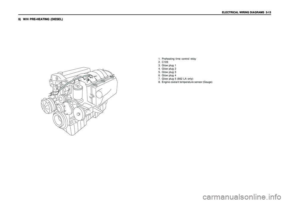
ELECTRICAL WIRING DIAGRAMS ELECTRICAL WIRING DIAGRAMSELECTRICAL WIRING DIAGRAMS ELECTRICAL WIRING DIAGRAMS
ELECTRICAL WIRING DIAGRAMS
2-13 2-13 2-13 2-13
2-13
9) 9)9) 9)
9)
W/H PRE-HEATING (DIESEL) W/H PRE-HEATING (DIESEL)W/H PRE-HEATING (DIESEL) W/H PRE-HEATING (DIESEL)
W/H PRE-HEATING (DIESEL)
1. Preheating time control relay
2. C109
3. Glow plug 1
4. Glow plug 2
5. Glow plug 3
6. Glow plug 4
7. Glow plug 5 (662 LA only)
8. Engine coolant temperature sensor (Gauge)
Page 1898 of 2053
1) VSS(VEHICLE SPEED SENSOR), METER(SPEEDO, TACHO) & GAUGE(FUEL, TEMPERATURE)
- GASOLINE ........................................................................................................................................................... 5-96
(1) W/O EURO III .................................................................................................................................................................................... 5-96
(2) W/ EURO III ....................................................................................................................................................................................... 5-98
2) WARNING LAMP(ENGINE CHECK, AIR BAG, EBD, ABS), TCS INDICATOR............................................. 5-100
3) INDICATOR(DEFROSTER, WINTER MODE, POWR MODE, 4WD LOW, 4WD HIGH, 4WD CHECK)..... 5-102
4) WARNING LAMP (SEAT BELT, DOOR OPEN, PARKING BRAKE), INDICATOR (BATTERY CHARGING,
GLOW).................................................................................................................................................................. 5-104
5) FRONT FOG LAMP, TURN SIGNAL, HAZARD, HIGH BEAM ......................................................................... 5-106
6) DIGITAL CLOCK,WARNING (OIL PRESSURE, LOW FUEL LEVEL) CLUSTER ILLUMINATION............... 5-108
7) SELECTOR LEVER POSITION LAMP (P,R,N,D,3,2,1).................................................................................... 5-110
19. 19.19. 19.
19.
STICS(SUPER STICS(SUPER STICS(SUPER STICS(SUPER
STICS(SUPER
TIME & ALARM INTEGRA TIME & ALARM INTEGRATIME & ALARM INTEGRA TIME & ALARM INTEGRA
TIME & ALARM INTEGRA
TED CONTR TED CONTRTED CONTR TED CONTR
TED CONTR
OL SYSTEM) OL SYSTEM)OL SYSTEM) OL SYSTEM)
OL SYSTEM)
................................ ................................................................ ................................
................................
5-112 5-112 5-112 5-112
5-112
1) STICS UNIT .......................................................................................................................................................... 5-112
2) FRONT WIPER CIRCUIT.................................................................................................................................... 5-114
3) CENTRAL DOOR LOCK SYSTEM ..................................................................................................................... 5-116
4) KEYLESS, KEY REMINDER SWITCH, SIREN, CHIME BELL BUZZER ........................................................ 5-118
5) DEFROSTER........................................................................................................................................................ 5-120
6) LAMP(ROOM, DOOR COURTESY LH/RH, LUGGAGE), DOOR CONTACT SWITCH .................................. 5-122
20. 20.20. 20.
20.
SEA SEASEA SEA
SEA
T HEA T HEAT HEA T HEA
T HEA
TER TERTER TER
TER
.......................................................................................................................... .................................................................................................................................................................................................................................................... ..........................................................................................................................
..........................................................................................................................
5-124 5-124 5-124 5-124
5-124
21. 21.21. 21.
21.
ST STST ST
ST
OP LAMP OP LAMPOP LAMP OP LAMP
OP LAMP
, ,, ,
,
BTSI (BRAKE BTSI (BRAKE BTSI (BRAKE BTSI (BRAKE
BTSI (BRAKE
TRANSMISSION SHIFT INTERLOCK) TRANSMISSION SHIFT INTERLOCK)TRANSMISSION SHIFT INTERLOCK) TRANSMISSION SHIFT INTERLOCK)
TRANSMISSION SHIFT INTERLOCK)
................................... ...................................................................... ...................................
...................................
5-126 5-126 5-126 5-126
5-126
1) METAL TOP .......................................................................................................................................................... 5-126
2) SOFT TOP............................................................................................................................................................ 5-128
22. 22.22. 22.
22.
POWER WINDOW POWER WINDOWPOWER WINDOW POWER WINDOW
POWER WINDOW
..................................................................................................................... .......................................................................................................................................................................................................................................... .....................................................................................................................
.....................................................................................................................
5-130 5-130 5-130 5-130
5-130
23. 23.23. 23.
23.
ELECTRIC OSRV (OUTSIDE REAR VIEW) MIRROR ELECTRIC OSRV (OUTSIDE REAR VIEW) MIRRORELECTRIC OSRV (OUTSIDE REAR VIEW) MIRROR ELECTRIC OSRV (OUTSIDE REAR VIEW) MIRROR
ELECTRIC OSRV (OUTSIDE REAR VIEW) MIRROR
........................................................... ...................................................................................................................... ...........................................................
...........................................................
5-132 5-132 5-132 5-132
5-132
24. 24.24. 24.
24.
REAR REAR REAR REAR
REAR
WIPER & WIPER & WIPER & WIPER &
WIPER &
W WW W
W
ASHER ASHERASHER ASHER
ASHER
...................................................................................................... ............................................................................................................................................................................................................ ......................................................................................................
......................................................................................................
5-134 5-134 5-134 5-134
5-134
25. 25.25. 25.
25.
CIGARETTE LIGHTER, HORN CIGARETTE LIGHTER, HORNCIGARETTE LIGHTER, HORN CIGARETTE LIGHTER, HORN
CIGARETTE LIGHTER, HORN
................................................................................................ ................................................................................................................................................................................................ ................................................................................................
................................................................................................
5-136 5-136 5-136 5-136
5-136
26.HEAD LAMP 26.HEAD LAMP26.HEAD LAMP 26.HEAD LAMP
26.HEAD LAMP
.............................................................................................................................. ............................................................................................................................................................................................................................................................ ..............................................................................................................................
..............................................................................................................................
5-138 5-138 5-138 5-138
5-138
27. 27.27. 27.
27.
HEAD LAMP LEVELING DEVICE (HLLD) HEAD LAMP LEVELING DEVICE (HLLD)HEAD LAMP LEVELING DEVICE (HLLD) HEAD LAMP LEVELING DEVICE (HLLD)
HEAD LAMP LEVELING DEVICE (HLLD)
.............................................................................. ............................................................................................................................................................ ..............................................................................
..............................................................................
5-140 5-140 5-140 5-140
5-140