Page 75 of 208
FUEL MIXTURE
Inlet manifold
12
Inlet manifold bolt and nut 2
TIGHTENING TORQUES (in daN.m)
REMOVAL
Remove:
- the air filter,
- the injector gallery (see section 13).
Lift the vehicle.
Remove the strut (1) (to gain access to the bolt
fixing the strut on the right-hand side of the vehi-
cle, remove the mudguard and the right-hand
wheel).
E7J engine
13339R2
Disconnect the accelerator cable and the electrical
connectors (2) connected to the throttle body.
Remove the bolts and nuts (3) securing the mani-
fold. Lower the vehicle.
Remove the air intake pipe (A) connecting the
throttle body to the air filter.
13335-1R
13130R
12-10
Page 121 of 208

DIESEL EQUIPMENT
Pump - Timing
13
IMPORTANT : the engine must only be rotated by
turning a wheel, in 5th gear, and in its operating
direction; if it is accidentally turned in the
opposite direction, repeat the operations for
checking and adjusting the timing.
CHECKING THE SETTING OF INJECTION PUMPS
FITTED WITH RAM PULLEYS
Turn the engine twice in the operating direction
(moving one wheel and having engaged 5th
gear).
Remove the timing shaft plug situated on the
pump cover.
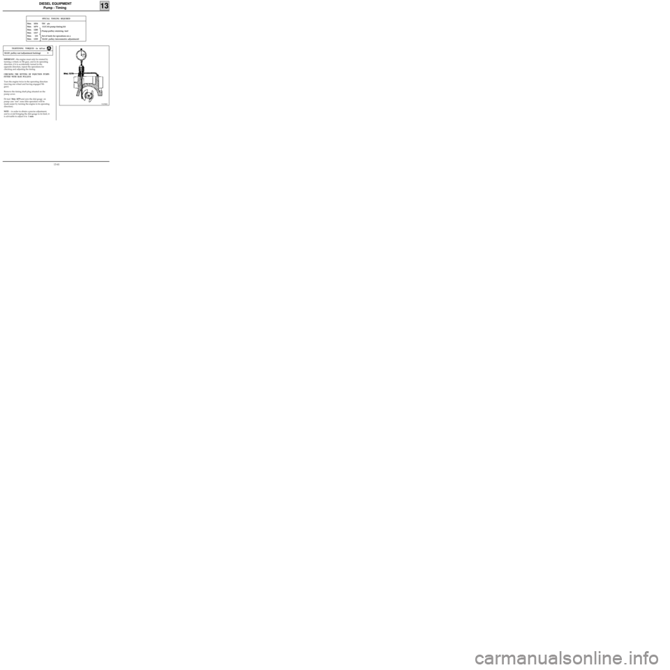
Fit tool Mot. 1079 and zero the dial gauge on
pump cam "rest" zone (this operation will be
made easier by turning the engine in its operating
direction).
NOTE : in order to obtain a precise adjustment,
and to avoid bringing the dial gauge to its limit, it
is advisable to adjust it to 1 mm.
SPECIAL TOOLING REQUIRED
Mot. 1054TDC pin
Mot. 1079 LUCAS pump timing kit
Mot. 1200
Mot. 1317
Mot. 135 Set of tools for operations on a
Mot. 1359 RAM pulley (micrometric adjustment)
91258R2
RAM pulley nut (adjustment locking) 9
TIGHTENING TORQUES (in daN.m)
Pump-pulley retaining tool
13-41
Page 181 of 208

COOLING
Water pump
CLEANING
It is very important not to scratch the gasket faces
of all aluminium components.
Use the product Décapjoint to dissolve the part
of the gasket which remains attached.
Apply the product to the part to be cleaned, wait
approximately 10 minutes, then remove it using a
wooden spatula.
The wearing of gloves is recommended during
this operation.
19
SPECIAL TOOLING REQUIRED
Mot. 1054TDC pin
Mot. 1202 Hose clip pliers
Mot. 1273 Tool for checking belt tension
Mot. 1289-03 Tool for centring the suspended en-
gine movement limiter
Mot. 1379 Tool for retaining engine on sub-
frame
10478S
D7F Engine
Crankshaft output mounting bolts 2 + 90°
Bolt for mounting front right suspended
engine mounting on engine 6.2
Bolt for mounting front right suspended
engine mounting on vehicle body 6.2
Timing belt tension wheel nut 5
Water pump mounting bolt 0.9
TIGHTENING TORQUES (in daN.m)
REMOVAL
Place the vehicle on a two post lift.
Disconnect the battery.
Remove:
- the timing belt (see method described in
section 11 "Timing belt),
- the power assisted steering pump pulley (if fit-
ted),
- the upper alternator mounting bolt and
slacken the lower bolt,
- the bolts for mounting the power assisted
steering pipe on the cylinder block,
- the bolts for mounting the power assisted
steering pump on its support (move the po-
wer assisted steering pump-pipe assembly to
one side),
- the power assisted steering pump support,
- the water pump hose,
- the tension wheel along with the water pump
itself.
19-7
Page 183 of 208

COOLING
Water pump
Refit the timing belt (see method described in
chapter 11 "Timing belt").
Fill and bleed the cooling circuit (see section 19
"Filling - Bleeding").
19
SPECIAL TOOLING REQUIRED
Mot. 591-02 Index
Mot. 591-04 Angle tightening wrench
Mot. 1135-01 Tool for tensioning the timing belt
Mot. 1202 Hose clip pliers
Mot. 1273 Tool for checking belt tension
92068R
E7J Engine
Tension wheel nut 5
Crankshaft pulley bolt 2 + 68° + 6°
Bolt for suspended engine mounting cover 6,2
Nut for suspended engine mounting cover 4,4
Water pump bolt 2,2
Water pump nut 1
Wheel bolts 9
TIGHTENING TORQUES (in daN.m)
EQUIPMENT REQUIRED
Engine support tool
REFITTING
The sealing of the water pump is carried out using
the product
LOCTITE 518; the bead (H) must be
applied following the diagram below.
REMOVAL
Place the vehicle on a two post lift.
Disconnect the battery.
Drain the cooling circuit from the lower radiator
hose.
Remove:
- the timing belt (see method described in
section 11 "Timing belt),
- the timing tension wheel,
- the water pump, and extract this from above.
CLEANING
It is very important not to scratch the gasket faces
of all aluminium components.
Use the product Décapjoint to dissolve the part
of the gasket which remains attached.
Apply the product to the part to be cleaned, wait
approximately 10 minutes, then remove it using a
wooden spatula.
The wearing of gloves is recommended during
this operation.
19-9
Page 184 of 208
COOLING
Water pump
19
SPECIAL TOOLING REQUIRED
Mot. 1202 Hose clip pliers
13090R
F8Q Engine
Water pump bolt 1.6
Bolt for water pump pulley 2
Bolt for crankshaft pulley 2 + 115° ± 15°
TIGHTENING TORQUES (in daN.m)
REMOVAL
Place the vehicle on a two post lift.
Disconnect the battery.
Drain the cooling circuit through the lower radia-
tor hose.
Fit the engine support tool.
Remove :
- the plastic protector for the suspended engine
mounting cover,
- the suspended engine mounting cover,
EQUIPMENT REQUIRED
Engine support tool
- the front right wheel arch,
- the accessories belt,
- the crankshaft pulley (A),
- the water pump pulley (B) , lowering the en-
gine as far as possible,
- the injection pump housing (C),
- the bolt at (1) and move the alternator to the
right.
13086R1
19-10
Page:
< prev 1-8 9-16 17-24