Page 128 of 208
ANTIPOLLUTION
Fuel vapour rebreathing
14
OPERATING DIAGRAM OF THE CIRCUIT
1 Inlet manifold
2 Fuel vapour absorber (canister)
3 RCO control solenoid valve
4 Cylinder head
R Pipe from fuel tank
99933R
PRC14.1
D7F Engine
14-2
Page 129 of 208
ANTIPOLLUTION
Fuel vapour rebreathing
14E7J Engine
OPERATING DIAGRAM OF THE CIRCUIT
1 Inlet manifold
2 Fuel vapour absorber (canister)
3 RCO control solenoid
4 Throttle body
R Pipe from fuel tank
13123R
14-3
Page 131 of 208

ANTIPOLLUTION
Fuel vapour rebreathing
14
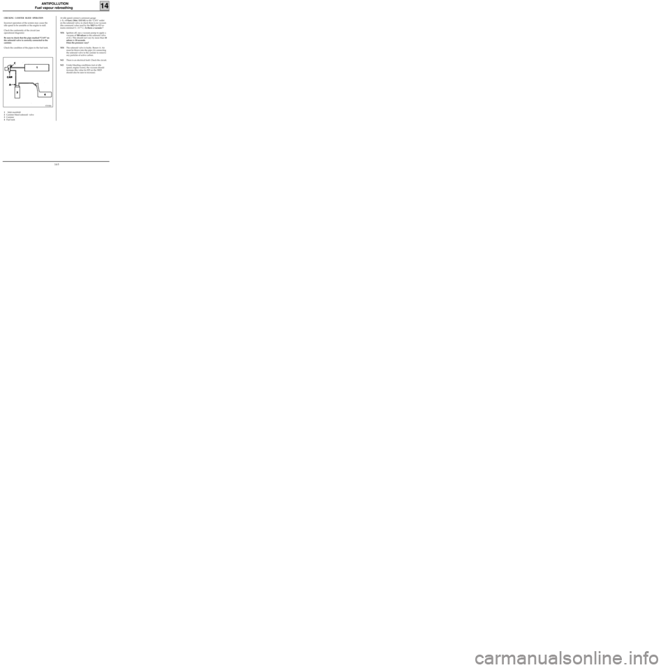
CHECKING CANISTER BLEED OPERATION
Incorrect operation of the system may cause the
idle speed to be unstable or the engine to stall.
Check the conformity of the circuit (see
operational diagrams)
Be sure to check that the pipe marked "CAN" on
the solenoid valve is correctly connected to the
canister.
Check the condition of the pipes to the fuel tank.
97393R6
1Inlet manifold
2Canister bleed solenoid valve
3Canister
4Fuel tankAt idle speed connect a pressure gauge
(- 3 ; +3 bars) (Mot. 1311-01) to the "CAN" outlet
on the solenoid valve, to check there is no vacuum
(the command value read by the
XR25 for #23 re-
mains minimal X = 0.7 % ). Is there a vacuum ?
YESIgnition off, use a vacuum pump to apply a
vacuum of 500 mbars to the solenoid valve
at (C). This should not vary by more than 10
mbars in 30 seconds.
Does the pressure vary?
YESThe solenoid valve is faulty. Renew it. Air
must be blown into the pipe (A) connecting
the solenoid valve to the canister to remove
any particles of active carbon.
NOThere is an electrical fault. Check the circuit.
NOUnder bleeding conditions (not at idle
speed, engine warm), the vacuum should
increase (the value for #23 on the XR25
should also be seen to increase).
14-5
Page 133 of 208
ANTIPOLLUTION
Oil vapour rebreathing
14
CIRCUIT DIAGRAM
1 Cylinder head cover
2 Inlet manifold
3 Oil vapour rebreathing pipe connected upstream from the throttle body (the circuit is used
for medium and high loads)
4 Oil vapour rebreathing pipe connected downstream from the throttle body
5 Air pipe
6 Throttle body
99932R
D7F Engine
14-7
Page 135 of 208
ANTIPOLLUTION
Oil vapour rebreathing
14E7J Engine
CIRCUIT DIAGRAM
1 Cylinder head
2 Inlet manifold
3 Oil vapour rebreathing pipe connected
upstream from the throttle body (the circuit is
used for medium and high loads)
4 Oil vapour rebreathing pipe connected
downstream from the throttle body
CHECKING
To ensure the correct operation of the
antipollution system, it is important to keep the
oil vapour rebreathing system clean and in good
working condition.
13335R
14-9
Page 178 of 208
COOLING
Diagram
19
1 Engine
2 Radiator
3 ”Hot” bottle with permanent degassing
4 Heater matrix
5 3 mm diameter restriction
The fan assembly is controlled at high speed by
the injection computer if the coolant tempera-
ture is greater than 99°C.
If the coolant temperature is lower than 96°C, the
fan assembly stops operating.Water pump
Thermostat
Bleed screw
The expansion bottle valve is brown, and its rating
is 1.2 bar.
10070-2R
D7F Engine
19-4
Page 179 of 208
COOLING
Diagram
19
1 Heater
2 Radiator
3 ”Hot” bottle with permanent degassing
4 Heater matrix
5 Thermostat mounting
6 3 mm diameter restriction
The fan assembly is controlled at high speed by
the injection computer if the coolant tempera-
ture is greater than 99°C.
If the coolant temperature is lower than 96°C, the
fan assembly stops operating.Water pump
Thermostat
Bleed screw
Temperature switch
The expansion bottle valve rating is 1.2 bar
(colour:brown).
13508R
E7J Engine
19-5
Page 180 of 208
COOLING
Diagram
19
Water pump
Thermostat
Bleed screw
Temperature switch
13504R
F8Q Engine
1 Heater
2 Radiator
3 ”Hot” bottle with permanent degassing
4 Heater matrix
5 Thermostat mounting
6 3 mm diameter restriction
The expansion bottle valve rating is 1.2 bar
(colour:brown).
19-6