Page 28 of 105
98991
REAR AXLE
Brake drum
Remove:
- the nut and stub axle washer,
- the drum.
The two brake drums must be of the same diameter, if one is reground, the other must also be reground.
Never exceed the diameter marked on the drum.
SPECIAL TOOLING REQUIRED
Emb. 880 Inertia extraction tool
Rou. 943 Hub cover plug extractor
TIGHTENING TORQUES (in daN.m)
Wheel bolts 9
Hub nut 17.5
REMOVAL
Remove the hub plug using tools Rou. 943 +
Emb. 880.
Release the handbrake, slacken the secondary
handbrake cables to allow the lever to move back.
Insert a screwdriver through one of the wheel
mounting holes in the drum and push the hand-
brake lever to release the lug from the brake
shoe( E ).
Help the lever to slacken by pushing it towards
the rear.
33
98990G
33-2
Page 55 of 105

STEERING ASSEMBLY
Manual steering rack
36
Put the vehicle on a two post lift.
REMOVAL
Remove the front wheels.
Cut the rubber gaiter retaining clip and push the
gaiter back towards the bulkhead.
Disconnect the ball joints using tool T.Av. 476.
Remove:
- the universal joint eccentric bolt,
- the steering rack mounting bolts on the sub-
frame.
Remove the steering rack.
SPECIAL TOOLING REQUIRED
Wheel bolts 9
Track rod end nut 3.7
Steering rack mounting bolts 5.5
Universal joint eccentric bolt 2.5
T.Av. 476 Ball joint extractor
TIGHTENING TORQUES (in daN.m)REFITTING
Refitting is the reverse of removal. Observe the
recommended tightening torques.
If a new steering rack is being fitted, fit the track
rod ends in the position noted on removal.
To do this, slacken the bolt on the parallelism
adjustment sleeve and slacken the track rod end
while holding the axial ball joint using an open
wrench.
Make a mark or count the number of turns of
thread taken up so the parallelism can be pre-
adjusted on refitting.
Check the parallelism.
NOTE : the markings on the track rod ends MUST
BE OBSERVED
(one mark on right hand joint, two
marks on left hand joint).
36-3
Page 56 of 105

STEERING ASSEMBLY
Power assisted steering rack
36
SPECIAL TOOLING REQUIRED
Mot. 453-01 Hose clamp pliers
T.Av. 476 Ball joint extractor
Wheel bolts 9
Track rod end nut 3.7
Steering rack mounting bolt 5
Universal joint eccentric bolt 2.5
Engine tie bar bolt 6.5
TIGHTENING TORQUES (in daN.m)
Put the vehicle on a two post lift.
REMOVAL
Remove the front wheels.
Fit a clamp Mot. 453-01 to each of the pipes from
the oil reservoir.
NOTE :never clamp the high pressure pipes.
Cut the rubber gaiter retaining clip and push the
gaiter back towards the bulkhead.
Disconnect the ball joints using tool T.Av. 476.
Remove the universal joint eccentric bolt.
Disconnect the oxygen sensor.
Remove the exhaust downpipe.
Remove the bolt (engine side) from the engine tie
bar and pivot the engine and transmission
assembly forwards.
Insert a retaining block.
Special notes for F8Q engine
Remove (from above) :
- the battery,
- the battery mounting,
- the high and low pressure pipes from the
steering valve.
13120S
36-4
Page 67 of 105
STEERING ASSEMBLY
Steering column
36
Under the vehicle, cut the retaining clip for the
rubber gaiter and push it back towards the
bulkhead.
Remove the eccentric bolt from the universal
joint.
Remove the two bolts and the two nuts mounting
the steering column.
12964R2
12965-1R2
Release:
- the steering column after disconnecting the
ignition switch,
- the gaiter from the bulkhead ( 1 ) and remove
it with the steering column.
REFITTING
Refit the steering column.
Fit the gaiter on the bulkhead, having tied the
flaps and the universal joint together with string.
Refitting is then the reverse of removal.
Check the instrument panel connectors are
correctly reconnected.
13116S
Remove the mounting bolts for the dashboard on
the steering column.
36-15
Page 69 of 105

MECHANICAL ELEMENT CONTROLS
Master cylinder
37
Hydraulic pipe unions 1.7
Mounting nut on brake servo 1.8
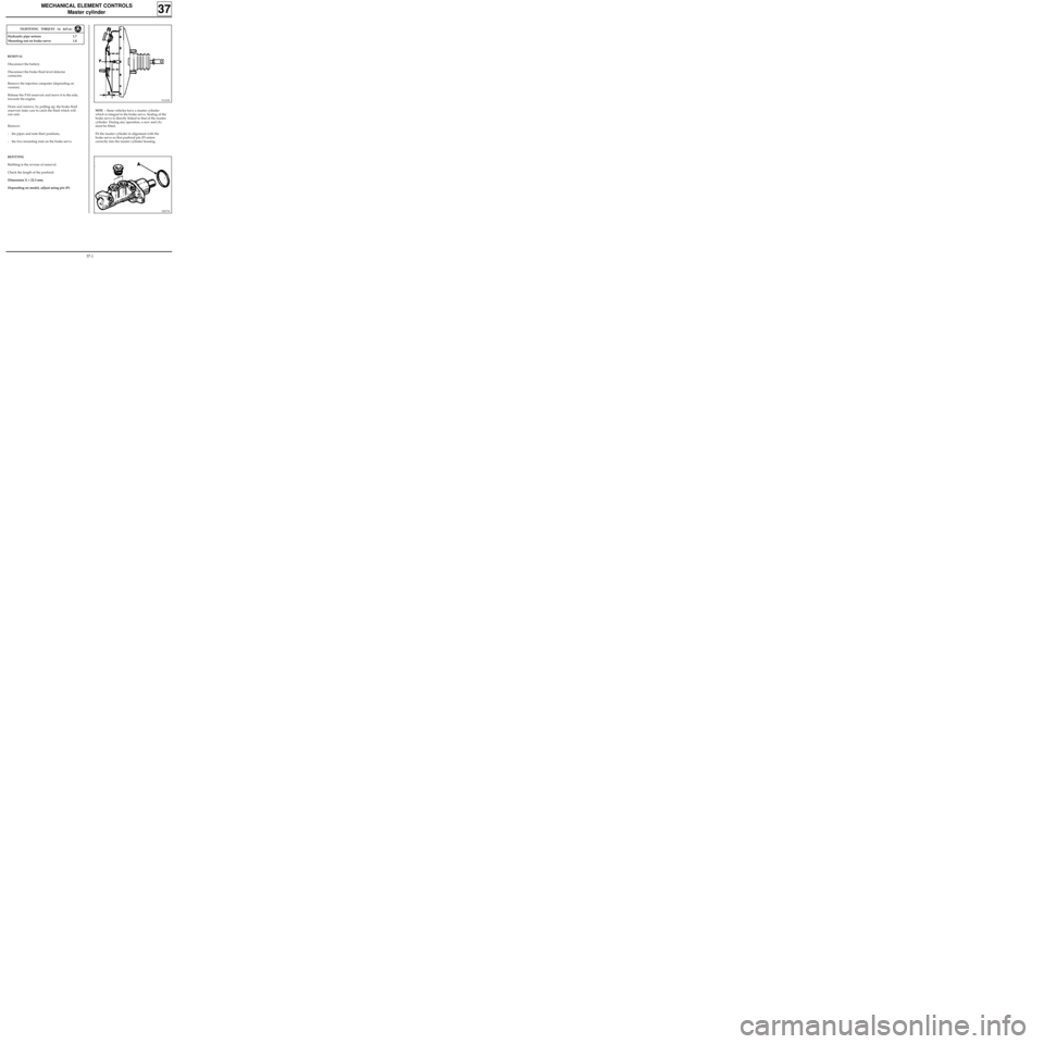
REMOVAL
Disconnect the battery.
Disconnect the brake fluid level detector
connector.
Remove the injection computer (depending on
version).
Release the PAS reservoir and move it to the side,
towards the engine.
Drain and remove, by pulling up, the brake fluid
reservoir (take care to catch the fluid which will
run out).
Remove:
- the pipes and note their positions,
- the two mounting nuts on the brake servo.
REFITTING
Refitting is the reverse of removal.
Check the length of the pushrod.
Dimension X = 22.3 mm.
Depending on model, adjust using pin (P).
91101R
NOTE : these vehicles have a master cylinder
which is integral to the brake servo. Sealing of the
brake servo is directly linked to that of the master
cylinder. During any operation, a new seal (A)
must be fitted.
Fit the master cylinder in alignment with the
brake servo so that pushrod pin (P) enters
correctly into the master cylinder housing.
TIGHTENING TORQUES (in daN.m)
DI3718
37-1
Page 71 of 105
MECHANICAL ELEMENT CONTROLS
Brake servo
TIGHTENING TORQUES (in daN.m)
Mounting nut on brake servo 1.8
Brake servo on bulkhead 2.3
- remove the 4 brake servo mounting nuts,
- remove the brake servo.
REFITTING
Before refitting, check:
-dimension L = 104.8 mm ,
-dimension X = 22.3 mm .The brake servo cannot be repaired. Operations
are only allowed on:
- the air filter,
- the non-return valve.
REMOVAL
Disconnect and remove the battery.
Remove:
- the master cylinder (following the method
described previously),
- the battery protection plate (4 bolts, 1 nut),
- the two mounting nuts for the expansion
bottle and move it towards the engine.
Disconnect the flexible vacuum hose from the
brake servo.
In the passenger compartment:
- remove the pin ( A ) from the clevice
connecting the brake pedal to the pushrod by
moving the clip,
37
91101R2
97860R
Refitting is the reverse of removal.
Bleed the brake circuit.
37-3