Page 34 of 105
REAR AXLE
Shock absorber
REMOVAL
With the vehicle on its wheels, remove the lower
mounting bolt (1).
Lift the vehicle and remove:
- the wheel,
- the upper mounting bolt (2),
- the shock absorber.
PRECAUTIONS TO BE TAKEN BEFORE FITTING
Shock absorbers are stored horizontally in the
Parts Stores.
Under these conditions it is possible that the shock
absorbers, which are designed to operate in a ver-
tical direction, will have de-primed.
Before fitting the shock absorbers to the vehicle
compress them a few times by hand in the vertical
position.
REFITTING
Fit:
- the shock absorber,
- the upper mounting bolt coated with
MOLYKOTE BR2, without tightening it,
- the wheel.
Lower the vehicle.
Position the lower mounting bolt coated with
MOLYKOTE BR2.
Torque tighten both bolts.
33
Upper mounting bolt 11.5
Lower mounting bolt 8.5
TIGHTENING TORQUES (in daN.m)
13133R
33-8
Page 35 of 105
REAR AXLE
Anti-roll bar, tubular rear axle
TIGHTENING TORQUES (in daN.m)
Bar mounting bolt 5.5
REMOVAL
1Mounting bolt
Put the vehicle on a lift with the wheels hanging
free.
On each side, remove bolts (1) and retain the
captive nuts.
Remove the bar.
REFITTING
On each side, refit the bolts (1) with the captive
nuts.
Tighten to the recommended torque.
33
13132R
33-9
Page 36 of 105

REAR AXLE
Half suspension arms, tubular rear axle
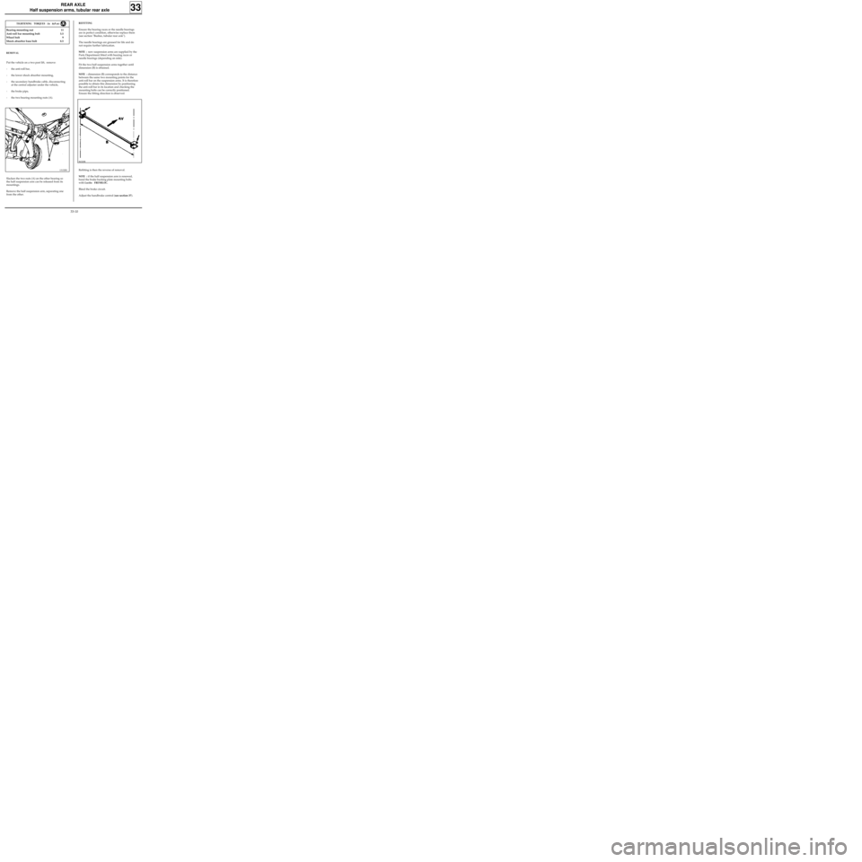
REFITTING
Ensure the bearing races or the needle bearings
are in perfect condition, otherwise replace them
(see section "Bushes, tubular rear axle").
The needle bearings are greased for life and do
not require further lubrication.
NOTE : new suspension arms are supplied by the
Parts Department fitted with bearing races or
needle bearings (depending on side).
Fit the two half suspension arms together until
dimension (B) is obtained.
NOTE : dimension (B) corresponds to the distance
between the same two mounting points for the
anti-roll bar on the suspension arms. It is therefore
possible to obtain this dimension by positioning
the anti-roll bar in its location and checking the
mounting bolts can be correctly positioned.
Ensure the fitting direction is observed.
Refitting is then the reverse of removal.
NOTE : if the half suspension arm is renewed,
bond the brake backing plate mounting bolts
with
Loctite FRENBLOC.
Bleed the brake circuit.
Adjust the handbrake control (see section 37).
33
TIGHTENING TORQUES (in daN.m)
Bearing mounting nut 11
Anti-roll bar mounting bolt 5.5
Wheel bolt 9
Shock absorber base bolt 8.5
REMOVAL
Put the vehicle on a two post lift, remove:
- the anti-roll bar,
- the lower shock absorber mounting,
- the secondary handbrake cable, disconnecting
at the central adjuster under the vehicle,
- the brake pipe,
- the two bearing mounting nuts (A).
Slacken the two nuts (A) on the other bearing so
the half suspension arm can be released from its
mountings.
Remove the half suspension arm, separating one
from the other.
13132R1
86320R
33-10
Page 41 of 105

REAR AXLE
Suspension bars, tubular rear axle
SPECIAL TOOLING REQUIRED
Emb. 880 Inertia extractor
TIGHTENING TORQUES (in daN.m)
Upper shock absorber mounting bolt 11.5
Lower shock absorber mounting bolt 8.5
REMOVAL
With the vehicle raised so its wheels hang free, re-
move the shock absorber on the side in question.
Remove the bar from the side, using tool
Emb. 880.
REFITTING
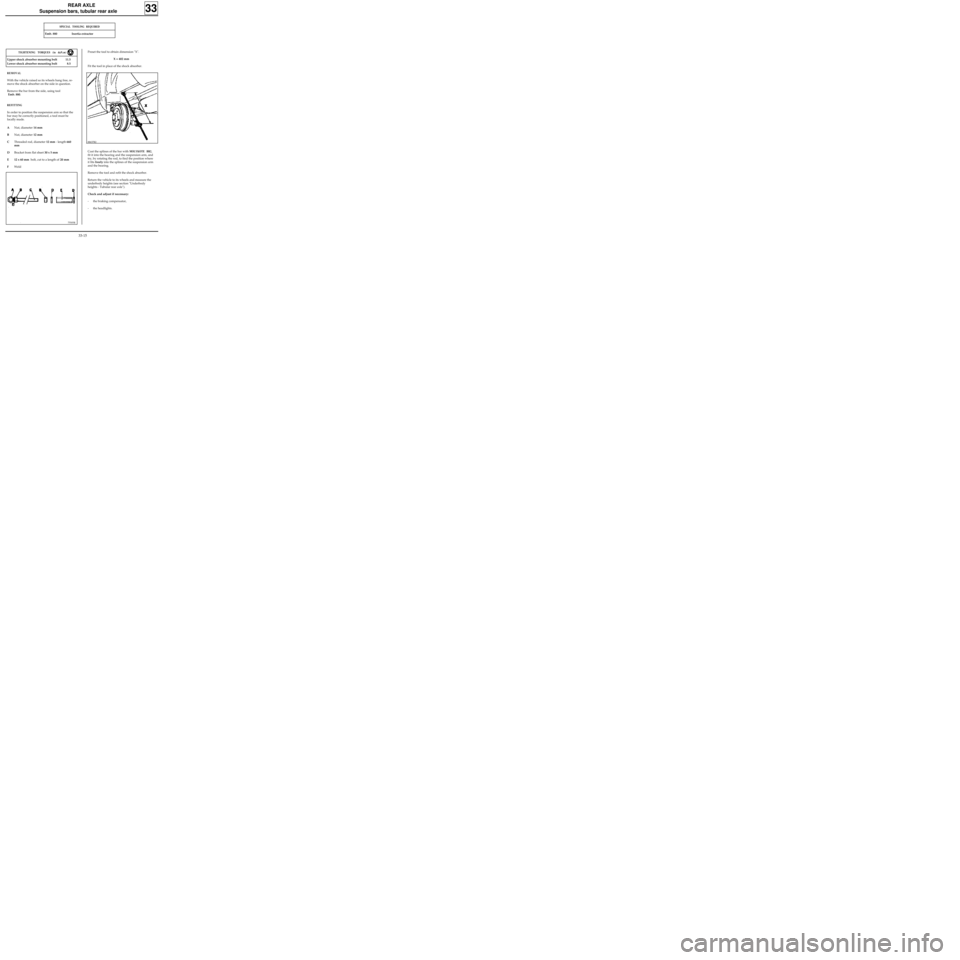
In order to position the suspension arm so that the
bar may be correctly positioned, a tool must be
locally made.
ANut, diameter 14 mm
BNut, diameter 12 mm
CThreaded rod, diameter 12 mm - length 660
mm
DBracket from flat sheet 30 x 5 mm
E 12 x 60 mm bolt, cut to a length of 20 mm
FWeld
33
75505R
Preset the tool to obtain dimension "X".
X = 402 mm
Fit the tool in place of the shock absorber.
88637R2
Coat the splines of the bar with MOLYKOTE BR2,
fit it into the bearing and the suspension arm, and
try, by rotating the rod, to find the position where
it fits freely into the splines of the suspension arm
and the bearing.
Remove the tool and refit the shock absorber.
Return the vehicle to its wheels and measure the
underbody heights (see section "Underbody
heights - Tubular rear axle").
Check and adjust if necessary:
- the braking compensator,
- the headlights.
33-15
Page 43 of 105
REAR AXLE
Four bar rear axle
SPECIAL TOOLING REQUIRED
Emb. 880 Inertia extractor
TIGHTENING TORQUES (in daN.m)
Upper shock absorber mounting 8.5
Lower shock absorber mounting 11.5
Wheel bolts 9
REMOVAL
Remove:
- the wheels,
- the shock absorbers,
- the suspension bar plugs.
Remove using tool Emb. 880 :
- the two suspension bars,
- the two anti-roll bars, retaining the central
shackle.
Clean and lubricate the bar splines using
MOLYKOTE BR2.
REFITTING
The anti-roll bars cannot be removed from the
vehicle when the shock absorber replacement tool
is in position. Because of this, and to make it
easier to refit the shackle, a wooden block must
be made according to the diagram below.
Fit:
- the shackle on the block (locally made) in the
centre of the rear axle assembly,
33
13135R
Dimensions in mm and degrees ( ° ).
33-17
Page 51 of 105
WHEELS AND TYRES
Specifications
The tyre inflation pressures are values for a fully laden vehicle or motorway use.
The tyre inflation pressure must be checked when cold. The increase in temperature during driving increases
the pressure by 0.2 to 0.3 bar.
If the inflation pressures are checked when the tyres are warm, take this pressure increase into consideration.
Never deflate a warm tyre.
(1) Reinforced tyre.
Chains
For safety reasons, chains may NEVER be fitted to the rear axle.
"Snow" or "thermorubber" tyres: all four wheels must be fitted with these tyres to retain vehicle adhesion as
far as possible.
35
TypeRim
Wheel bolt
torque
(daN.m)
Tyres
Inflation pressure
(bar) cold
FrontRear
FC0X
KC0X
5 B 13
5 B 13
5,5 J 14
9
2.8
2.6
2.4
3.6
2.9
3.0
165/70 R 13 C 88/86
165/70 R 13 83 (1)
165/70 R 14
35-3
Page 53 of 105
STEERING ASSEMBLY
Axial ball joint
36
Put the vehicle on a two post lift.
REMOVAL
Disconnect the track rod end using tool T.Av. 476.
Slacken the bolt on the parallelism adjustment
sleeve and slacken the track rod end while
holding the axial ball joint using an open wrench.
Make a mark or count the number of turns of
thread taken up so the parallelism can be pre-
adjusted on refitting.
Remove the plastic retaining clip for the gaiter
and remove the gaiter.
SPECIAL TOOLING REQUIRED
Wheel bolts 9
Track rod end nut 3.7
Bolt on parallelism adjustment sleeve 1.7
Axial ball joint 5
Dir. 1305-01 Tool for removing - refitting
axial ball joint
Dir. 1306 Tool for retaining SMI unit rack
T.Av. 476 Ball joint extractor
TIGHTENING TORQUES (in daN.m)Turn the wheels so the rack teeth are freed on the
valve side.
Fit tool Dir. 1306.
In this position, release the axial ball joint using
tool Dir. 1305-01.
97469R1
36-1
Page 54 of 105
STEERING ASSEMBLY
Axial ball joint
36
REFITTING
Assembly (2) MUST be renewed systematically.
83510-1R3
Refit to the rack (3) :
- the stop washer assembled with the locking
ring (2),
- the new axial ball joint (1) having lightly coated
the threads with
LOCTITE FREN-BLOC, ensuring
that the air evacuation opening is not blocked.
Before finally tightening the axial ball joint using
tool Dir. 1305-01, check that the tabs on the
locking ring (2) align with the flats (B) on the rack.
Tighten the axial ball joint to the recommended
torque.
Centre the steering to equalise the air in the
gaiters.
Fit a new gaiter and secure it with a new clip
(after greasing the gaiter bearing surface on the
axial ball joint).
Checking
Gently press on the gaiter to check the other
gaiter inflates which indicates the air is circulating
correctly.
36-2