Page 131 of 203

7Do-it-yourself operations
Maintenance precautions .......................................7-2
Engine compartment check locations ....................7-3
Engine cooling system ...........................................7-4
Checking engine coolant level ...............................7-4
Changing engine coolant .......................................7-5
Engine oil ...............................................................7-7
Checking engine oil level .......................................7-7
Changing engine oil ...............................................7-8
Changing engine oil filter .......................................7-9
Automatic transmission fluid (ATF) ........................7-9
Temperature conditions for checking ATF ...........7-10
Power steering fluid..............................................7-11
Brake and clutch fluid...........................................7-11
Window washer fluid ............................................7-12
Battery ..................................................................7-13
Jump starting ........................................................7-14
Drive belts ............................................................7-14Spark plug replacement .......................................7-15
Air cleaner housing filter ......................................7-16
Wiper blades ........................................................7-17
Parking brake check.............................................7-18
Brake pedal ..........................................................7-18
Brake booster .......................................................7-19
Clutch pedal .........................................................7-20
Fuses ....................................................................7-20
Fusible links..........................................................7-21
Light bulbs ............................................................7-22
Headlights ............................................................7-22
Headlight aiming adjustment ................................7-23
Adjustment after headlight assembly
replacement ..........................................................7-24
Bulb replacement .................................................7-25
Wheels and tires ..................................................7-29
ZX
Page 152 of 203

HEADLIGHTS
The headlight is a semi-sealed beam type
which uses a replaceable headlight (halo-
gen) bulb.
CAUTION
cHigh pressure halogen gas is sealed
inside the halogen bulb. The bulb
may break if the glass envelope is
scratched or the bulb is dropped.
cWhen handling the bulb, do not
touch the glass envelope.
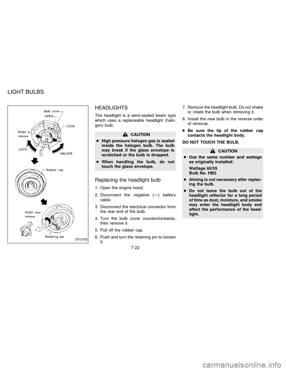
Replacing the headlight bulb
1. Open the engine hood.
2. Disconnect the negative (Ð) battery
cable.
3. Disconnect the electrical connector from
the rear end of the bulb.
4. Turn the bulb cover counterclockwise,
then remove it.
5. Pull off the rubber cap.
6. Push and turn the retaining pin to loosen
it.7. Remove the headlight bulb. Do not shake
or rotate the bulb when removing it.
8. Install the new bulb in the reverse order
of removal.
cBe sure the lip of the rubber cap
contacts the headlight body.
DO NOT TOUCH THE BULB.
CAUTION
cUse the same number and wattage
as originally installed:
Wattage 60/55
Bulb No. HB2
cAiming is not necessary after replac-
ing the bulb.
cDo not leave the bulb out of the
headlight reflector for a long period
of time as dust, moisture, and smoke
may enter the headlight body and
affect the performance of the head-
light.
DI1316S
LIGHT BULBS
7-22
ZX
Page 153 of 203
HEADLIGHT AIMING
ADJUSTMENT
Before performing aiming adjustment, make
sure of the following:
a. Keep all of the tires inflated to the correct
pressure.
b. Place the vehicle on level ground.
c. See that the vehicle is unloaded (except
for full levels of coolant, engine oil and
fuel, and spare tire, jack, and tools).
Have the driver or an equivalent weight
placed in the driver's seat.
Low beam
1. Open the hood.
2. Adjust the vertical indicator by turning the
adjusting screw with a Phillips screw-
driver. The bubble in the gauge should
be centered on the ``0'' mark.3. Adjust the horizontal indicator by turning
the adjusting screw with a Phillips screw-
driver.
The inner red line with the ``0'' mark
should align with the indicator line. Never
turn screw
sAas indicated in earlier
illustration.
ADI0085ADI0526ADI0096
7-23
ZX
Page 154 of 203
ADJUSTMENT AFTER
HEADLIGHT ASSEMBLY
REPLACEMENT
If the vehicle has had front body repair and
the headlight assembly has been replaced,
the aiming should be checked using the
aiming chart as shown in the illustration.
a. Adjust headlights so that main axis of
light is parallel to center line of body
and is aligned with point P shown in
the illustration.
b. Dotted lines in illustration show cen-
ter of headlight.
H: Horizontal center line of head-
lights
W: Distance between each headlight
center
L: Distance between the headlights
and the wall that the lights are
tested against. 7.62 m (25 ft)
C: Distance below the horizontal cen-
ter line of the light (ªHº) used in
determining the main axis of light.
106 mm (4.17 in)
H-C=M
M = main axis of lightEven if the horizontal indicator does not
align with the indicator line or the bubble is
not centered in the water level after aiming
by the chart, it is acceptable if the lines are
within the OK ranges.
ADI0505
7-24
ZX