1997 MERCEDES-BENZ ML500 spark plugs
[x] Cancel search: spark plugsPage 2279 of 4133
crankshaft in its standard
direction of rotation.
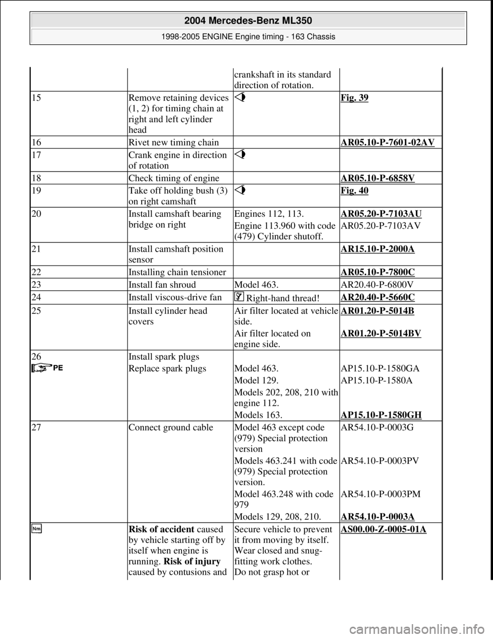
15Remove retaining devices
(1, 2) for timing chain at
right and left cylinder
head Fig. 39
16Rivet new timing chain AR05.10-P-7601-02AV
17Crank engine in direction
of rotation
18Check timing of engine AR05.10-P-6858V
19Take off holding bush (3)
on right camshaft Fig. 40
20Install camshaft bearing
bridge on rightEngines 112, 113.AR05.20-P-7103AU
Engine 113.960 with code
(479) Cylinder shutoff.AR05.20-P-7103AV
21Install camshaft position
sensor AR15.10-P-2000A
22Installing chain tensioner AR05.10-P-7800C
23Install fan shroudModel 463.AR20.40-P-6800V
24Install viscous-drive fan Right-hand thread!AR20.40-P-5660C
25Install cylinder head
coversAir filter locat ed at vehicle
side.AR01.20-P-5014B
Air filter located on
engine side.AR01.20-P-5014BV
26Install spark plugs
Replace spark plugsModel 463.AP15.10-P-1580GA
Model 129.AP15.10-P-1580A
Models 202, 208, 210 with
engine 112.
Models 163.AP15.10-P-1580GH
27Connect ground cableModel 463 except code
(979) Special protection
versionAR54.10-P-0003G
Models 463.241 with code
(979) Special protection
version.AR54.10-P-0003PV
Model 463.248 with code
979AR54.10-P-0003PM
Models 129, 208, 210.AR54.10-P-0003A
Risk of accident caused
by vehicle starting off by
itself when engine is
running. Risk of injury
caused by contusions and Secure vehicle to prevent
it from moving by itself.
Wear closed and snug-
fitting work clothes.
Do not grasp hot or AS00.00-Z-0005-01A
2004 Mercedes-Benz ML350
1998-2005 ENGINE Engine timing - 163 Chassis
me
Saturday, October 02, 2010 3:39:37 PMPage 38 © 2006 Mitchell Repair Information Company, LLC.
Page 2320 of 4133
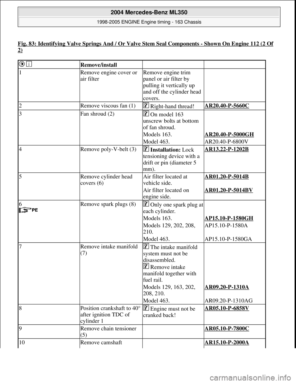
Fig. 83: Identifying Valve Springs And / Or Valve Stem Seal Components -Shown On Engine 112 (2 Of
2)
Remove/install
1Remove engine cover or
air filterRemove engine trim
panel or air filter by
pulling it vertically up
and off the cylinder head
covers.
2Remove viscous fan (1) Right-hand thread!AR20.40-P-5660C
3Fan shroud (2) On model 163
unscrew bolts at bottom
of fan shroud.
Models 163.AR20.40-P-5000GH
Model 463.AR20.40-P-6800V
4Remove poly-V-belt (3) Installation: Lock
tensioning device with a
drift or pin (diameter 5
mm).AR13.22-P-1202B
5Remove cylinder head
covers (6)Air filter located at
vehicle side.AR01.20-P-5014B
Air filter located on
engine side.AR01.20-P-5014BV
6
Remove spark plugs (8)Only one spark plug at
each cylinder.
Models 163.AP15.10-P-1580GH
Models 129, 202, 208,
210.AP15.10-P-1580A
Model 463.AP15.10-P-1580GA
7Remove intake manifold
(7) The intake manifold
system must not be
disassembled.
Remove intake
manifold together with
fuel rail.
Models 129, 163, 202,
208, 210.AR09.20-P-1310A
Model 463.AR09.20-P-1310AG
8Position crankshaft to 40°
after ignition TDC of
cylinder 1 Engine must not be
cranked back!AR05.10-P-6858V
9Remove chain tensioner
(5) AR05.10-P-7800C
10Remove camshaft AR15.10-P-2000A
2004 Mercedes-Benz ML350
1998-2005 ENGINE Engine timing - 163 Chassis
me
Saturday, October 02, 2010 3:39:38 PMPage 79 © 2006 Mitchell Repair Information Company, LLC.
Page 2382 of 4133
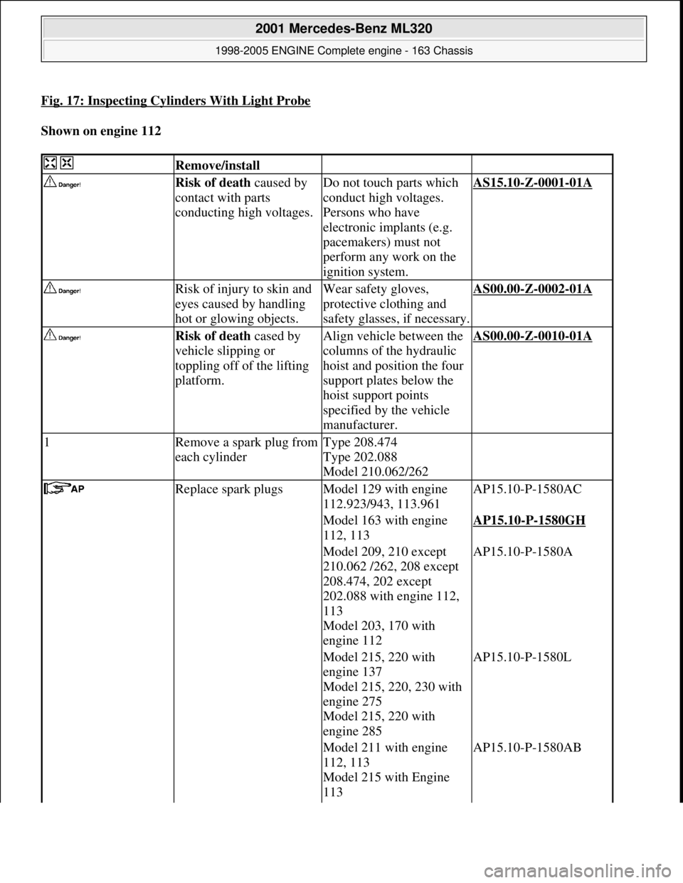
Fig. 17: Inspecting Cylinders With Light Probe
Shown on engine 112
Remove/install
Risk of death caused by
contact with parts
conducting high voltages.Do not touch parts which
conduct high voltages.
Persons who have
electronic implants (e.g.
pacemakers) must not
perform any work on the
ignition system.AS15.10-Z-0001-01A
Risk of injury to skin and
eyes caused by handling
hot or glowing objects.Wear safety gloves,
protective clothing and
safety glasses, if necessary.AS00.00-Z-0002-01A
Risk of death cased by
vehicle slipping or
toppling off of the lifting
platform.Align vehicle between the
columns of the hydraulic
hoist and position the four
support plates below the
hoist support points
specified by the vehicle
manufacturer.AS00.00-Z-0010-01A
1Remove a spark plug from
each cylinderType 208.474
Type 202.088
Model 210.062/262
Replace spark plugsModel 129 with engine
112.923/943, 113.961AP15.10-P-1580AC
Model 163 with engine
112, 113AP15.10-P-1580GH
Model 209, 210 except
210.062 /262, 208 except
208.474, 202 except
202.088 with engine 112,
113
Model 203, 170 with
engine 112AP15.10-P-1580A
Model 215, 220 with
engine 137
Model 215, 220, 230 with
engine 275
Model 215, 220 with
engine 285AP15.10-P-1580L
Model 211 with engine
112, 113
Model 215 with Engine
113 AP15.10-P-1580AB
2001 Mercedes-Benz ML320
1998-2005 ENGINE Complete engine - 163 Chassis
me
Saturday, October 02, 2010 3:17:56 PMPage 26 © 2006 Mitchell Repair Information Company, LLC.
Page 2386 of 4133
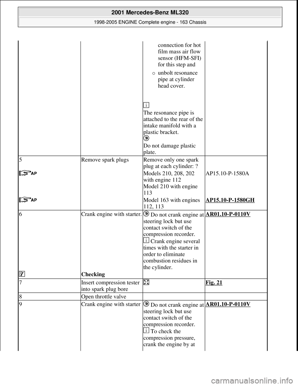
connection for hot
film mass air flow
sensor (HFM-SFI)
for this step and
unbolt resonance
pipe at cylinder
head cover.
The resonance pipe is
attached to the rear of the
intake manifold with a
plastic bracket.
Do not damage plastic
plate.
5Remove spark plugsRemove only one spark
plug at each cylinder: ?
Models 210, 208, 202
with engine 112
Model 210 with engine
113AP15.10-P-1580A
Model 163 with engines
112, 113AP15.10-P-1580GH
6Crank engine with starter.Do not crank engine at
steering lock but use
contact switch of the
compression recorder.
Crank engine several
times with the starter in
order to eliminate
combustion residues in
the cylinder.AR01.10-P-0110V
Checking
7Insert compression tester
into spark plug bore Fig. 21
8Open throttle valve
9Crank engine with starterDo not crank engine at
steering lock but use
contact switch of the
compression recorder.
To check the
compression pressure,
crank the engine by at AR01.10-P-0110V
2001 Mercedes-Benz ML320
1998-2005 ENGINE Complete engine - 163 Chassis
me
Saturday, October 02, 2010 3:17:56 PMPage 30 © 2006 Mitchell Repair Information Company, LLC.
Page 2390 of 4133
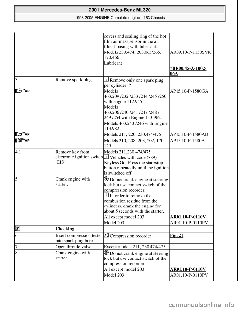
covers and sealing ring of the hot
film air mass sensor in the air
filter housing with lubricant.
Models 230.474, 203.065/265,
170.466AR09.10-P-1150SVK
Lubricant
*BR00.45
-Z-1002-
06A
3Remove spark plugs Remove only one spark plug
per cylinder: ?
Models
463.209 /232 /233 /244 /245 /250
with engine 112.945.AP15.10-P-1580GA
Models
463.206 /240 /241 /247 /248 /
249 /254 with Engine 113.962.
Models 463.243 /246 with Engine
113.982
Models 211, 220, 230.474/475AP15.10-P-1580AB
Models 210, 208, 203, 202, 170,
129AP15.10-P-1580A
4.1Remove key from
electronic ignition switch
(EIS)Models 211,230.474/475
Vehicles with code (889)
Keyless Go: Press the start/stop
button repeatedly until the ignition
is switched off.
5Crank engine with
starter. Do not crank engine at steering
lock but use contact switch of the
compression recorder.
In order to remove the
combustion residue from the
cylinders, crank the engine for
about 5 seconds with the starter.
All except model 203AR01.10-P-0110V
Model 203AR01.10-P-0110PV
Checking
6Insert compression tester
into spark plug bore Compression recorderFig. 21
7Open throttle valveExcept models 211, 230.474/475
8Crank engine with
starter. Do not crank engine at steering
lock but use contact switch of the
compression recorder.
All except model 203AR01.10-P-0110V
Model 203AR01.10-P-0110PV
2001 Mercedes-Benz ML320
1998-2005 ENGINE Complete engine - 163 Chassis
me
Saturday, October 02, 2010 3:17:56 PMPage 34 © 2006 Mitchell Repair Information Company, LLC.
Page 2411 of 4133
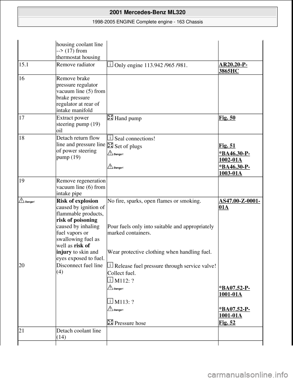
housing coolant line
--> (17) from
thermostat housing
15.1Remove radiator Only engine 113.942 /965 /981.AR20.20-P-
3865HC
16Remove brake
pressure regulator
vacuum line (5) from
brake pressure
regulator at rear of
intake manifold
17Extract power
steering pump (19)
oil Hand pumpFig. 50
18Detach return flow
line and pressure line
of power steering
pump (19) Seal connections!
Set of plugsFig. 51
*BA46.30-P-
1002-01A
*BA46.30-P-
1003-01A
19Remove regeneration
vacuum line (6) from
intake pipe
Risk of explosion
caused by ignition of
flammable products,
risk of poisoning
caused by inhaling
fuel vapors or
swallowing fuel as
well as risk of
injury to skin and
eyes exposed to fuel.No fire, sparks, ope n flames or smoking.AS47.00-Z-0001-
01A
Pour fuels only into suitable and appropriately
marked containers.
Wear protective clothing when handling fuel.
20Disconnect fuel line
(4) Release fuel pressure through service valve!
Collect fuel.
M112: ?
*BA07.52-P-
1001-01A
M113: ?
*BA07.52-P-
1001-01A
Pressure hoseFig. 52
21Detach coolant line
(14)
2001 Mercedes-Benz ML320
1998-2005 ENGINE Complete engine - 163 Chassis
me
Saturday, October 02, 2010 3:17:56 PMPage 55 © 2006 Mitchell Repair Information Company, LLC.
Page 2431 of 4133
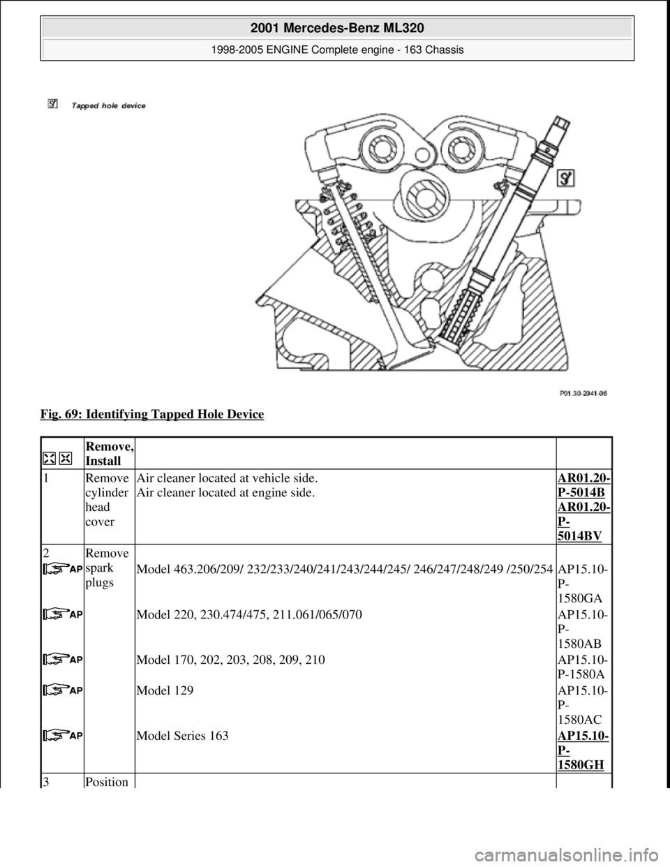
Fig. 69: Identifying Tapped Hole Device
Remove,
Install
1Remove
cylinder
head
coverAir cleaner located at vehicle side.
Air cleaner located at engine side.AR01.20-
P-5014B
AR01.20-
P-
5014BV
2Remove
spark
plugs
Model 463.206/209/ 232/233/240/241/243/ 244/245/ 246/247/248/249 /250/254AP15.10-
P-
1580GA
Model 220, 230.474/475, 211.061/065/070AP15.10-
P-
1580AB
Model 170, 202, 203, 208, 209, 210AP15.10-
P-1580A
Model 129AP15.10-
P-
1580AC
Model Series 163AP15.10-
P-
1580GH
3Position
2001 Mercedes-Benz ML320
1998-2005 ENGINE Complete engine - 163 Chassis
me
Saturday, October 02, 2010 3:17:56 PMPage 75 © 2006 Mitchell Repair Information Company, LLC.
Page 2583 of 4133
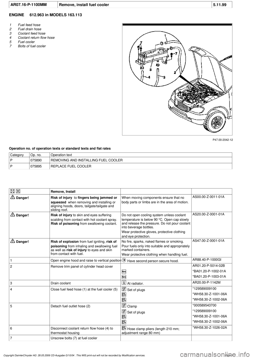
AR07.16-P-1100MM
Remove, install fuel cooler
5.11.99
ENGINE
612.963 in MODELS 163.113
P47.00-2042-12
1
Fuel feed hose
2
Fuel drain hose
3
Coolant feed hose
4
Coolant return flow hose
5
Fuel cooler
7
Bolts of fuel cooler
Operation no. of operation texts or standard texts and flat rates
Category
Op. no.
Operation text
P
075890
REMOVING AND INSTALLING FUEL COOLER
P
075895
REPLACE FUEL COOLER
Remove, Install
Danger!
Risk of injury
to
fingers being jammed or
squeezed
when removing and installing or
aligning hoods, doors, tailgate/tailgate and
sliding roof.
When moving components ensure that no
body parts or limbs are in the area of motion.
AS00.00-Z-0011-01A
Danger!
Risk of injury
to skin and eyes suffering
scalding from contact with hot coolant spray.
Risk of poisoning
from swallowing coolant.
Do not open cooling system unless coolant
temperature is below 90 °C. Open cap slowly
and release the pressure. Do not pour coolant
into beverage bottles.
Wear protective gloves, protective clothing
and eye protection.
AS20.00-Z-0001-01A
Danger!
Risk of explosion
from fuel igniting,
risk of
poisoning
from inhaling and swallowing fuel
as well as
risk of injury
to eyes and skin
from contact with fuel.
No fire, sparks, naked flames or smoking.
Pour fuels only into suitable and appropriately
marked containers.
Wear protective clothing when handling fuel.
AS47.00-Z-0001-01A
1
Open engine hood and raise to vertical position
Have second person secure hood.
AR88.40-P-1000GI
2
Remove trim panel of cylinder head cover
AR01.20-P-5014-02B
*BA01.20-P-1002-01A
*BA01.20-P-1003-01A
3
Drain coolant
At radiator.
AR20.00-P-1142M
4
Close fuel feed hose (1) at the fuel cooler (5)
Set of plugs
*129589009100
*WH58.30-Z-1001-06A
*WH58.30-Z-1002-06A
5
Detach fuel outlet hose (2)
Clamp
*000589543700
Set of plugs
*129589009100
*WH58.30-Z-1001-06A
*WH58.30-Z-1002-06A
6
Disconnect coolant return flow hose (4) to
thermostat housing
Hose clamp pliers (length 210 mm;
adjustment range 80 mm)
*WH58.30-Z-1026-02A
7
Unscrew bolts (7) at fuel cooler
Copyright DaimlerChrysler AG 28.05.2006 CD-Ausgabe G/10/04 . This WIS print-out will not be recorde
d by Modification services.
Page 1