1997 MERCEDES-BENZ ML500 ESP
[x] Cancel search: ESPPage 173 of 4133
123 Interior equipment
Te ch n ica l
data Instruments
and controlsOperationDrivingInstrument
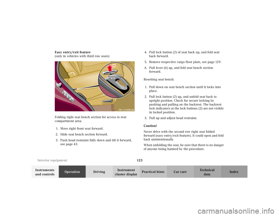
cluster displayPractical hints Car care Index Easy entry/exit feature
(only in vehicles with third row seats)
Folding right seat bench section for access to rear
compartment area:
1. Move right front seat forward.
2. Slide seat bench section forward.
3. Push head restraint fully down and tilt it forward,
see page 43.4. Pull lock button (2) of seat back up, and fold seat
back forward.
5. Remove respective cargo floor plate, see page 129.
6. Pull lever (6) up, and fold seat bench section
forward.
Resetting seat bench:
1. Pull down on seat bench section until it locks into
place.
2. Pull lock button (2) up, and unfold seat back to
upright position. Check for secure locking by
pushing and pulling on the backrest. The backrest
lock indicators at the lock buttons (2) are not visible
in locked position.
3. Pull up and adjust head restraint.
Caution!
Never drive with the second row right seat folded
forward (easy entry/exit feature). It could open and fold
back unintentionally.
When unfolding the seat, be sure that there is no danger
of anyone being harmed by the procedure.
Page 191 of 4133
141 Garage door opener
Te ch n ica l
data Instruments
and controlsOperationDrivingInstrument
cluster displayPractical hints Car care Index For operation in the USA only: This device complies
with Part 15, Subpart C, Section 209 of the FCC Rules.
Operation is subject to the following two conditions:
(1) This device may not cause harmful interference, and
(2) this device must accept any interference received,
including interference that may cause undesired
operation.
WARNING: Changes or modification not expressly
approved by party responsible for compliance could void
the user’s authority to operate the equipment.
Programming or reprogramming the integrated
remote control:
1. Turn key in steering lock to position 1 or 2.
2. Hold the end of the hand-held transmitter of the
device you wish to train approximately 2 to 5 inches
(5 cm to 12 cm) away from the surface of the
integrated remote control located on the overhead
console, keeping the indicator lamp in view.3. Using both hands, simultaneously push the hand-
held transmitter button and the desired integrated
remote control button. Do not release the buttons
until completing step 4.
4. The indicator lamp on the integrated remote control
will flash, first slowly and then rapidly. When the
indicator lamp flashes rapidly, both buttons may be
released (the rapid flashing lamp indicates
successful programming of the new frequency
signal). To program the remaining two buttons,
follow ste ps 1 through 4.
Note:
If after repeated attempts, you do not successfully
program the integrated remote control device to learn
the signal of the hand-held transmitter, the garage door
opener could be equipped with the “rolling code
feature”.
Page 195 of 4133
145 Contents - Driving
Te ch n ica l
data Instruments
and controlsOperationDrivingInstrument
cluster displayPractical hints Car care Index
DrivingControl and operation of
radio transmitters ..................... 146
The first 1 000 miles
(1 500 km) ................................. 147
Maintenance ................................... 147
Tele Aid ........................................... 148
Catalytic converter ........................ 160
Emission control ............................ 161
Steering lock ................................... 162
Starting and turning off
the engine .................................. 164
Automatic transmission ............... 165
Parking brake ................................. 173Driving instructions .......................174
Drive sensibly – save fuel .........174
Drinking and driving .................174
Pedals ...........................................174
Power assistance ........................ 175
Brakes .......................................... 175
Driving off .................................... 176
Parking ......................................... 176
Tires ............................................. 177
Snow chains ............................... 179
Winter driving instructions ......180
Deep water ...................................181
Passenger compartment ............182
Traveling abroad .........................182Off-Road driving ............................. 183
Trailer towing ................................. 190
Cruise control ................................. 196
Brake assist system (BAS) ............ 199
Antilock brake system (ABS) ....... 201
Four-wheel electronic
traction system (4-ETS+) ..........203
Electronic brake
proportioning (EBP) ..................204
Electronic stability program
(ESP) ...........................................205
Transmission control –
LOW RANGE mode ...................209
What you should know
at the gas station ....................... 212
Check regularly and
before a long trip ...................... 215
Page 196 of 4133
146 Control and operation of radio transmitters
Te ch n ica l
data Instruments
and controlsOperationDrivingInstrument
cluster displayPractical hints Car care Index
Control and operation of radio transmitters
MCS, radio and telephone
1 Observe all legal requirements.
Telephones and two-way radio
Radio transmitters, such as a portable telephone or a
citizens band unit should only be used inside the
vehicle if they are connected to an antenna that is
installed on the outside of the vehicle.
Refer to the radio transmitter operation instructions
regarding use of an external antenna.
Wa r n i n g !
Please do not forget that your primary
responsibility is to drive the vehicle. Only operate
the MCS, radio or telephone
1 if road and traffic
conditions permit.
Bear in mind that at a speed of just 30 mph
(approximately 50 km / h), your vehicle is covering
a distance of approximately 50 feet (approximately
14 m ) e v e r y s e c o n d .
Wa r n i n g !
Never operate radio transmitters equipped with a
built-in or attached antenna (i.e. without being
connected to an external antenna) from inside the
vehicle while the engine is running. Doing so could
lead to a malfunction of the vehicle’s electronic
system, possibly resulting in an accident and
personal injury.
Page 198 of 4133
148 Tele Aid
Te ch n ica l
data Instruments
and controlsOperationDrivingInstrument
cluster displayPractical hints Car care Index
Tele Aid
Important!
The initial activation of the Tele Aid system may only be
performed by completing the subscriber agreement and
placing an acquaintance call using the “SOS” button.
Failure to complete either of these steps will result in a
system that is not activated. If the system is not
activated the indicator lamp in the “SOS” button stays
on after turning electronic key in starter switch to
position 2 and the message “TELE AID – NOT
ACTIVATED” will be shown in the MCS display for
approx. 10 seconds.
If you have any questions regarding activation, please
call the Response Center at 1-800-756-9018 (in the USA)
or 1-888-923-8367 (in Canada).
(Telematic Alarm Identification on Demand)
The Tele Aid system consists of three types of response;
automatic and manual emergency, roadside assistance
and information.The Tele Aid system is operational providing that the
vehicle’s battery is charged, properly connected, not
damaged and cellular and GPS coverage is available.
The speaker volume of a Tele Aid call can be adjusted
using the volume control on the MCS unit. To activate,
press the “SOS” button, the Roadside Assistance
button• or the Information button¡, depending
on the type of response required.
Shortly after the completion of your Acquaintance Call,
you will receive a user ID and password via first call
mail. By visiting www.mbusa.com and selecting
“Tele Aid” (USA only), you will have access to account
information, remote door unlock, Info Services
* profile
and more.
* OptionalSystem self-check
Initially, after turning the key in steering lock to
position 2, malfunctions are detected and indicated (the
indicator lamps in the “SOS” button, the Roadside
Assistance button• and Information button¡
stay on longer than 10 seconds or do not come on). The
message “TELE AID – PLEASE VISIT WORKSHOP”
appears in the MCS display.
Page 199 of 4133
149 Tele Aid
Te ch n ica l
data Instruments
and controlsOperationDrivingInstrument
cluster displayPractical hints Car care Index Important!
Always make sure that the indicator lamps in the
“SOS” button, the Roadside Assistance button• and
the Information button¡do not remain illuminated
constantly in red and the message “TELE AID – VISIT
WORKSHOP” is not displayed in the MCS display after
the system self check.
If a malfunction is indicated as outlined above, have the
system checked at the nearest Mercedes-Benz Light
Truck Center as soon as possible.
Emergency calls
An emergency call is initiated automatically:
•following an accident in which the Emergency
Tensioning Retractors (ETR’s) or airbags deploy,
•if the antitheft alarm or the tow away alarm stays on
for more than 20 seconds, see pages 35 and 36.
An emergency call can also be initiated manually by
opening the cover next to the inside rear view mirror
labeled “SOS”, then pressing the button (for longer than
2 seconds) located under the cover. See below for
instructions on initiating an emergency call manually.Once the emergency call is in progress, the indicator
lamp in the “SOS” button will begin to f lash. The
message “EMERGENCY CALL – CONNECTING CALL”
appears in the MCS display. When the connection is
established, the message “EMERGENCY CALL – CALL
CONNECTED” appears in the MCS display. All
information relevant to the emergency, such as the
location of the vehicle (determined by the GPS satellite
location system), vehicle model, identification number
and color are generated.
A voice connection between the Response Center and
the occupants of the vehicle will be established
automatically soon after the emergency call has been
initiated. When a voice connection is established the
audio system mutes and the message “TELE AID –
EMERGENCY CALL ACTIVE” appears in the MCS
display. The Response Center will attempt to determine
more precisely the nature of the accident provided they
can speak to an occupant of the vehicle.
Page 200 of 4133
150 Tele Aid
Te ch n ica l
data Instruments
and controlsOperationDrivingInstrument
cluster displayPractical hints Car care Index
The Tele Aid system is available if:
•it has been activated and is operational. Activation
requires a subscription for monitoring services and
cellular air time
•the relevant cellular phone network and GPS signals
are available and pass the information on to the
response center.
Note:
Location of the vehicle on a map is possible if the
vehicle is able to receive signals from the GPS satellite
network and pass the information on to the response
center.
Wa r n i n g !
If the indicator lamp in the “SOS” button is
illuminated continuously and there was no voice
connection to the Response Center established,
then the Tele Aid system could not initiate an
emergency call (e.g. the relevant cellular phone
network is not available). The message
“EMERGENCY CALL – CALL FAILED” appears in
the MCS display for approx. 10 seconds.Should this occur, assistance must be summoned
by oth er means.
Page 201 of 4133
151 Tele Aid
Te ch n ica l
data Instruments
and controlsOperationDrivingInstrument
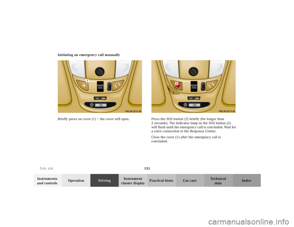
cluster displayPractical hints Car care Index Initiating an emergency call manually
Briefly press on cover (1) – the cover will open. Press the SOS button (2) briefly (for longer than
2 seconds). The indicator lamp in the SOS button (2)
will flash until the emergency call is concluded. Wait for
a voice connection to the Response Center.
Close the cover (1) after the emergency call is
concluded.
������������������������� �������������������������������������������������� ����������������������
����
RESET
MODE
1������������������������������������������������������������������������������������������
����������
RESET
MODE
2