1997 MERCEDES-BENZ ML500 radio
[x] Cancel search: radioPage 196 of 4133
146 Control and operation of radio transmitters
Te ch n ica l
data Instruments
and controlsOperationDrivingInstrument
cluster displayPractical hints Car care Index
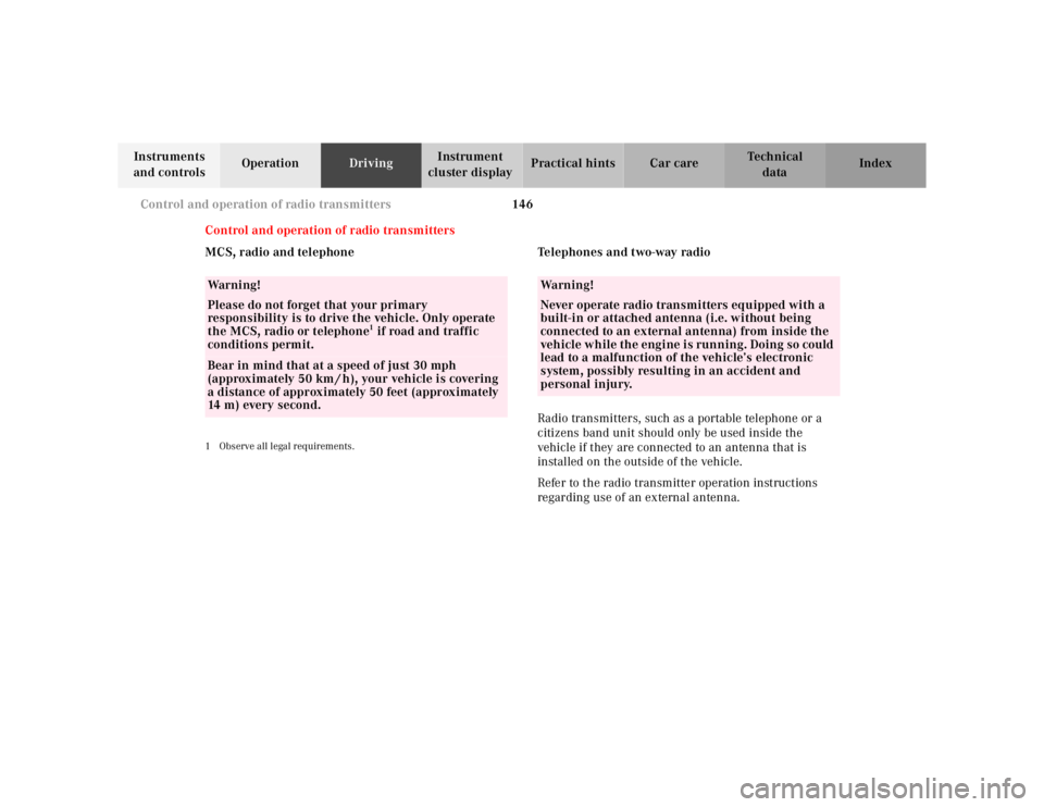
Control and operation of radio transmitters
MCS, radio and telephone
1 Observe all legal requirements.
Telephones and two-way radio
Radio transmitters, such as a portable telephone or a
citizens band unit should only be used inside the
vehicle if they are connected to an antenna that is
installed on the outside of the vehicle.
Refer to the radio transmitter operation instructions
regarding use of an external antenna.
Wa r n i n g !
Please do not forget that your primary
responsibility is to drive the vehicle. Only operate
the MCS, radio or telephone
1 if road and traffic
conditions permit.
Bear in mind that at a speed of just 30 mph
(approximately 50 km / h), your vehicle is covering
a distance of approximately 50 feet (approximately
14 m ) e v e r y s e c o n d .
Wa r n i n g !
Never operate radio transmitters equipped with a
built-in or attached antenna (i.e. without being
connected to an external antenna) from inside the
vehicle while the engine is running. Doing so could
lead to a malfunction of the vehicle’s electronic
system, possibly resulting in an accident and
personal injury.
Page 207 of 4133

157 Tele Aid
Te ch n ica l
data Instruments
and controlsOperationDrivingInstrument
cluster displayPractical hints Car care Index Important!
If the indicator lamp continues to flash or the system
does not reset, contact the Response Center at
1-800-756-9018 (in the USA) or 1-888-923-8367 (in
Canada), or Mercedes-Benz Client Assistance at
1-800-FOR-MERCedes (1-800-367-6372) in the USA or
Customer Service at 1-800-387-0100 in Canada.
Notes:
The indicator lamp for the respective button flashes
until the call is concluded and this can only be
completed by a Response Center or Client Assistance
Center representative, except Roadside assistance and
Information calls, which can also be terminated by
using the End button on the MCS unit.
When a Tele Aid call has been initiated, the MCS system
audio is muted and the selected mode (radio, tape or
CD) pauses. The optional cellular phone (if installed)
switches off. If you must use this phone, the vehicle
must be parked. Disconnect the coiled cord and place
the call. The navigation system (if engaged) will
continue to run. A pop-up window will appear in the
MCS display to indicate that a Tele Aid call is in
progress.Remote door unlock
In the case you have your vehicle locked unintentionally
(e.g. key inside vehicle), and the reserve key is not
handy, contact the Mercedes-Benz Response Center at
1-800-756-9018 (in the USA) or 1-888-923-8367 (in
Canada). You will be asked to provide your password
which you provided when you completed the subscriber
agreement.
Then return to your vehicle and pull outside handle of
liftgate for a minimum of 20 seconds until the “SOS”
button is flashing.
As an alternative, you may unlock the vehicle via
Internet using the ID and password sent to you shortly
after the completion of your Acquaintance Call.
The Response Center will then unlock your vehicle with
the remote door unlocking feature.
Note:
The remote door unlock feature is available if the
relevant cellular phone network is available.
The SOS button will f lash and the message
“EMERGENCY CALL – CALL CONNECTED” will appear
in t he MCS display to indica te receipt of t he d oor unlock
command.
Page 352 of 4133

302 Index
Te ch n ica l
data Instruments
and controlsOperation DrivingInstrument
cluster displayPractical hints Car careIndex
Clock, adjusting ............................................................... 80
Compartment under front passenger seat ..................116
Consumer information ..................................................298
Control and operation of radio transmitters ............. 146
Coolant level
Adding ........................................................................235
Checking ....................................................................234
Low engine coolant level warning ..........................224
Coolant temperature gauge ............................................ 81
Coolants ...........................................................................296
Anticorrosion/antifreeze quantity .........................296
Low engine coolant level warning ..........................224
Cover blind, cargo area ................................................. 137
Cruise control ................................................................. 196
Cup holder
Instrument panel .......................................................116
Rear center console ...................................................117
DDaytime running lamps .................................................. 91
Deep water
Driving instructions ................................................. 181
Defroster, rear window .................................................. 103
Display illumination ........................................................ 80Doors .................................................................................. 30
Drinking and driving ..................................................... 174
Drive sensibly - save fuel .............................................. 174
Driving instructions ...................................................... 174
Driving off ....................................................................... 176
EEBP (Electronic brake proportioning) ........................ 204
Electrical outlet ............................................................. 230
Electronic brake proportioning (EBP) ........................ 204
Electronic stability program (ESP) ............................. 205
Control switch .......................................................... 207
Malfunction indicator lamp .....................................221
Synchronizing .......................................................... 206
Warning lamp ............................................................221
Electronic traction system (4-ETS+) ........................... 203
LOW RANGE – 4-ETS ............................................... 204
Malfunction indicator lamp .....................................221
Emergency call
See Tele Aid ...............................................................148
Emergency operation of Skyview Top ....................... 273
Emergency tensioning retractor (ETR) .........................55
Emergency unlocking in case of accident ...................33
Emission control ............................................................ 161
Page 356 of 4133

306 Index
Te ch n ica l
data Instruments
and controlsOperation DrivingInstrument
cluster displayPractical hints Car careIndex
Parking lamp ...................................................... 90, 264
Replacing bulbs .........................................................260
Side marker lamp ......................................................264
Standing lamp .................................................... 90, 264
Taillamp assemblies .................................................265
Turn signal lamp ................................................ 90, 264
Turn signal lamp, side .............................................266
Layout of poly-V-belt ......................................................286
Liftgate ............................................................................... 34
Unlocking ..................................................................... 28
Lighter ..............................................................................119
Limp home mode (Automatic transmission) ............. 172
Loading instructions ..................................................... 136
Lockable storage compartment .....................................116
Locking and unlocking the vehicle ............................... 27
Low engine coolant level warning ..............................224
Low engine oil level warning .......................................224
LOW RANGE
Indicator lamp ........................................................... 221
LOW RANGE mode ........................................................209
LOW RANGE – 4-ETS+ .............................................204
LOW RANGE – ABS ..................................................202
LOW RANGE – ESP ...................................................208
MMaintenance ...................................................................147
Malfunction and indicator lamps in the instrument
cluster ......................................................................... 218
Manual locking/unlocking the doors ...........................29
Manual operation of Skyview Top .............................. 273
Manual operation of sliding/pop-up roof .................. 272
Manual seat, front ............................................................39
MCS, radio and telephone ............................................146
Mechanical keys ............................................................... 29
Memory .............................................................................42
Recalling ....................................................................... 42
Storing ........................................................................... 42
Mirror, exterior, adjusting ..............................................73
Mirror, exterior, rear view ..............................................73
Mirror, inside, rear view ................................................. 71
Mirrors, vanity ................................................................ 113
Page 357 of 4133

307 Index
Te ch n ica l
data Instruments
and controlsOperation DrivingInstrument
cluster displayPractical hints Car careIndex
OObtaining replacement keys .......................................... 25
Odometer/Trip odometer ................................................ 80
Off-Road driving ............................................................. 183
On-board diagnostic system ......................................... 218
Operator’s manual ............................................................. 8
Outside temperature indicator ...................................... 82
Overhead control panel ................................................... 21PPanic button ...................................................................... 28
Parking .............................................................................176
Parking brake ....................... 118, 173, 175, 176, 219, 245
Partition net .................................................................... 133
Poly-V-belt
Layout .........................................................................286
Power assistance ............................................................ 175
Power seats, front ............................................................ 40
Memory ........................................................................ 42
Memory recalling ....................................................... 42
Memory storing ........................................................... 42Power windows ...............................................................104
Blocking of rear door windows ............................... 105
Express opening of front door windows ................ 105
Problems with your vehicle ............................................ 15
Product information .......................................................... 7
RRadio transmitters ......................................................... 146
Rain sensor
See windshield wiper/washer switch ......................95
Rear quarter windows ...................................................106
Rear seat bench ..............................................................120
Easy entry/exit feature ............................................123
Head restraints ..........................................................124
Rear seat head restraints ..............................................124
Adjusting ....................................................................125
Removal ......................................................................125
Rear view mirrors
Exterior ......................................................................... 73
Inside ............................................................................ 71
Rear window defroster .................................................. 103
Rear window wiper/washer ...........................................96
Page 359 of 4133

309 Index
Te ch n ica l
data Instruments
and controlsOperation DrivingInstrument
cluster displayPractical hints Car careIndex Special settings (Climate control) ............................... 101
Split rear seat bench ..................................................... 120
Easy entry/exit feature ............................................ 123
Rear seat head restraints ......................................... 124
SRS indicator lamp ........................................................ 219
SRS malfunction .............................................................. 57
Start lock-out .................................................................... 25
Starting and turning off the engine ............................ 164
Steering lock ................................................................... 162
Steering wheel
Adjustable .................................................................... 70
Indicator lamp ...........................................................222
Stop lamp, high mounted .............................................267
Storage compartments
Center console ............................................................115
Compartment under front passenger seat .............116
Glove box .....................................................................115
Stowing things in the vehicle ......................................230
Stranded vehicle ............................................................259
Sun visors ........................................................................113
Supplemental restraint system (SRS) ........................... 54
Synchronizing remote control ..................................... 271
TTachometer ........................................................................82
Technical data ................................................................ 287
Electrical system ...................................................... 290
Main dimensions ...................................................... 291
Rims and tires ..................................................288, 289
Weights ...................................................................... 290
Tele Aid ............................................................................ 148
Emergency calls ........................................................149
Information ................................................................ 154
Initiating an emergency call manually .................. 151
Roadside Assistance ................................................. 152
Telephone, general ......................................................... 139
Telephones and two-way radios ................................... 146
Telescoping steering column
Adjusting ......................................................................70
Indicator lamp .......................................................... 222
The first 1 000 miles (1 500 km) ................................147
Third row seats ...............................................................126
Tie-down rings, cargo .................................................... 132
Tire inflation pressure ................................................. 250
Tire traction ....................................................................178
Page 368 of 4133
DISABLING SYSTEM
Before proceeding, see AIR BAG SAFETY PRECAUTIONS . Record radio presets and obtain anti-theft
code. Turn ignition switch to OFF position and remove ignition key. If welding on vehicle, disconnect negative
battery cable and disconnect air bag control module.
ACTIVATING SYSTEM
Ensure ignition is off. Reconnect air bag system co mponents (if disconnected). Reconnect negative battery
cable. Perform See SYSTEM OPERATION CHECK
.
DISPOSAL PROCEDURES
Several situations may arise requiring so me form of disposal action, including:
Scrapping a vehicle containing a deployed air bag module and-or ETR.
Scrapping a vehicle with a live air bag module and-or ETR.
Disposal of a live but electrically faulty air bag module and-or ETR.
Disposal of a deployed air bag module and-or ETR.
DEPLOYED AIR BAG OR ETR
Deployed air bag module and-or ETR unit can be thrown away. None of its components are reusable. Deployed
air bag module is NOT classified as hazardous material.
SCRAPPED VEHICLE
1. Before proceeding, follow service precautions. See AIR BAG SAFETY PRECAUTIONS . Move
vehicle outdoors to a remote area, away from work shop and other personnel. Disconnect and shield
negative battery cable. Open al l vehicle windows and doors.
2. Ensure air bag module is secured to steering wheel, and passenger air bag is secured to dash. Ensure ETR
seat belt assemblies are secured to "B" pillars and all seat belt buckles are latched. Remove loose ob
jects
CAUTION: On CL500, open doors before
disconnecting battery. Opening doors
allows windows to automa tically lower thus preventing roof seal damage.
WARNING: An undeployed air bag module or ET R should never be disposed of
without first being deplo yed. See SCRAPPED VEHICLE
. If deployment is
not possible, contact vehicle manuf acturer for further instructions.
WARNING: An undeployed air bag m odule and-or ETR seat belt CANNOT be disposed
of without first being de ployed. If this is not possible through procedures
outlined below, contact vehicle ma nufacturer for further instructions.
Perform remote deployment outdoors . Keep personnel at least 20 feet
away.
2001 Mercedes-Benz ML320
2000-01 ACCESSORIES/SAFETY EQUIPMENT Merc edes-Benz - Air Bag Restraint Systems
me
Saturday, October 02, 2010 3:44:45 PMPage 4 © 2006 Mitchell Repair Information Company, LLC.
Page 370 of 4133

assembly. To install, reverse removal pr ocedure. Activate air bag system. See DISABLING &
ACTIVATING AIR BAG SYSTEM . Perform system operation check to ensure system is functioning
properly. See SYSTEM OPERATION CHECK
.
CONTROL MODULE
Removal & Installation (C Class)
1. Before proceeding, See AIR BAG SAFETY PRECAUTIONS . Disable air bag system. See
DISABLING & ACTIVATI NG AIR BAG SYSTEM
. Remove ignition key. Remove shift lever cover
bezel. Lift shift lever cover e nough to disconnect electrical connector . Remove shift lever cover.
2. Remove storage compartment mount ing screws from center console. Remove storage compartment.
Remove ashtray. Disconnect electrical connectors as necessary. Disconnect SRS control module electrical
connector. Remove SRS contro l module mounting bolts. Remove SRS control module.
3. To install, reverse removal proce dure. Ensure SRS control module arro w points to front of vehicle. Set
parameters and program new SRS control module wi th Hand-Held Tester (965 589 00 01 00). Activate
air bag system. Perform system operation check to ensure system is functioning properly. See SYSTEM
OPERATION CHECK .
Removal & Installation (E Class)
1. Before proceeding, See AIR BAG SAFETY PRECAUTIONS . Disable air bag system. See
DISABLING & ACTIVATI NG AIR BAG SYSTEM
. Remove ignition key. Remove gear shift cover
panel. Remove ashtray and ashtray housing at front of console. Remove radio (if necessary).
2. Remove center console right side cover screws and ri ght side cover. Disconnect electrical connector for
control module. Remove 2 control module m ounting screws. Remove control module.
3. To install, reverse removal proce dure. Ensure SRS control module arro w points to front of vehicle. Set
parameters and program new SRS control module wi th Hand-Held Tester (965 589 00 01 00). Activate
air bag system. Perform system operation check to ensure system is functioning properly. See SYSTEM
OPERATION CHECK .
Removal & Installation (S Class)
1. Before proceeding, See AIR BAG SAFETY PRECAUTIONS . Disable air bag system. See
DISABLING & ACTIVATI NG AIR BAG SYSTEM
. Remove ignition key. Remove radio. Remove
ashtray. Remove wooden surround for ashtray. Remove shift lever cover mounting screws. Push shift
lever cover toward rear of vehicle and remove in an upward direction.
2. Remove center console cover screws. Remove cente r console cover by pulling from bottom in an upward
direction. When removing covers, di sconnect electrical connectors as necessary. Disconnect SRS control
module electrical connector. Re move SRS control module.
3. To install, reverse removal proce dure. Ensure SRS control module arro w points to front of vehicle. Set
parameters and program new SRS control module wi th Hand-Held Tester (965 589 00 01 00). Activate
air bag system. Perform system operation check to ensure system is functioning properly. See SYSTEM
OPERATION CHECK .
Removal & Installation (SL Class)
2001 Mercedes-Benz ML320
2000-01 ACCESSORIES/SAFETY EQUIPMENT Merc edes-Benz - Air Bag Restraint Systems
me
Saturday, October 02, 2010 3:44:45 PMPage 6 © 2006 Mitchell Repair Information Company, LLC.