Page 539 of 4133
72
Rear view mirrors
Te ch n ica l
data
Instruments
and controls Operation
Driving Instrument
cluster display Practical hints Car care Index
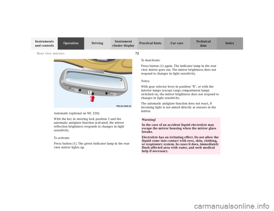
Automatic (optional on ML 320):
With the key in steering lock position 2 and the
automatic antiglare function activated, the mirror
reflection brightness responds to changes in light
sensitivity.
To a ctiva te:
Press button (1). The green indicator lamp in the rear
view mirror lights up. To deactivate:
Press button (1) again. The indicator lamp in the rear
view mirror goes out. The mirror brightness does not
respond to changes in light sensitivity.
Notes:
With gear selector lever in position “R”, or with the
interior lamps (except cargo compartment lamp)
switched on, the mirror brightness does not respond to
changes in light sensitivity.
The automatic antiglare function does not react, if
incoming light is not aimed directly at sensors in the
mirror.
Wa r n i n g !
In the case of an accident liquid electrolyte may
escape the mirror housing when the mirror glass
breaks.Electrolyte has an irritating effect. Do not allow the
liquid come into contact with eyes, skin, clothing,
or respiratory system. In cases it does, immediately
flush affected area with water, and seek medical
help if necessary.
Page 541 of 4133
74
Rear view mirrors
Te ch n ica l
data
Instruments
and controls Operation
Driving Instrument
cluster display Practical hints Car care Index
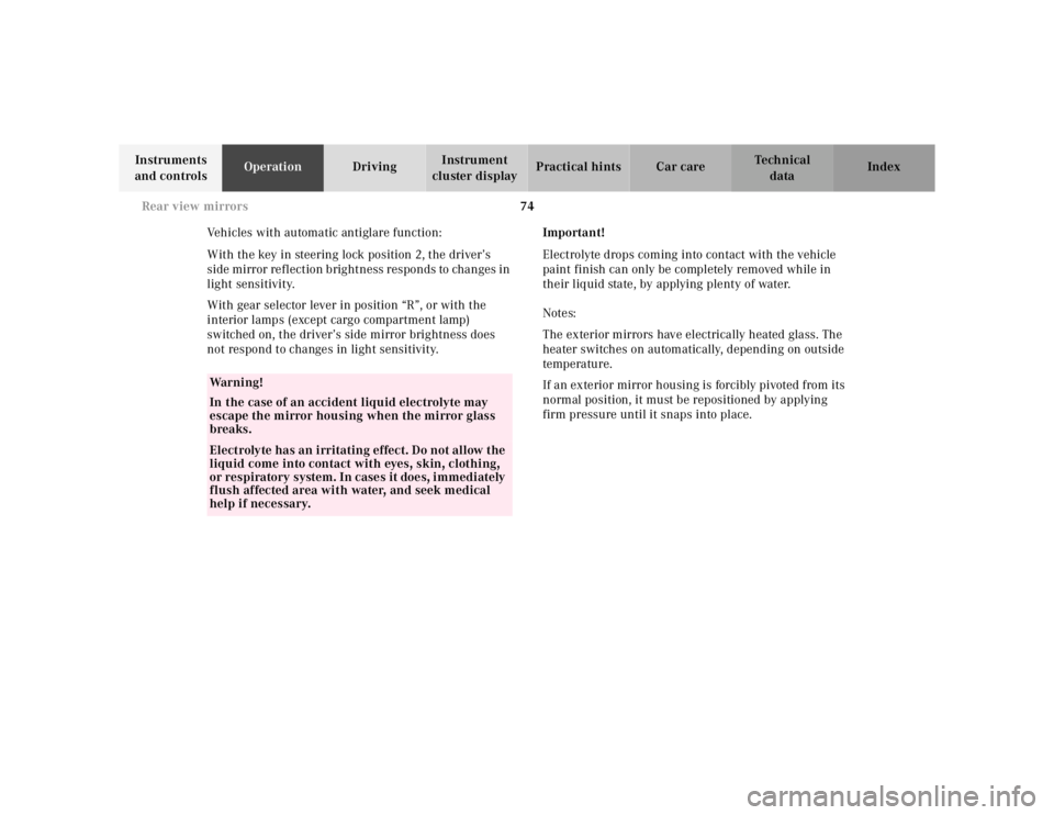
Vehicles with automatic antiglare function:
With the key in steering lock position 2, the driver’s
side mirror reflection brightness responds to changes in
light sensitivity.
With gear selector lever in position “R”, or with the
interior lamps (except cargo compartment lamp)
switched on, the driver’s side mirror brightness does
not respond to changes in light sensitivity. Important!
Electrolyte drops coming into contact with the vehicle
paint finish can only be completely removed while in
their liquid state, by applying plenty of water.
Notes:
The exterior mirrors have electrically heated glass. The
heater switches on automatically, depending on outside
temperature.
If an exterior mirror housing is forcibly pivoted from its
normal position, it must be repositioned by applying
firm pressure until it snaps into place.
Wa r n i n g !
In the case of an accident liquid electrolyte may
escape the mirror housing when the mirror glass
breaks.Electrolyte has an irritating effect. Do not allow the
liquid come into contact with eyes, skin, clothing,
or respiratory system. In cases it does, immediately
flush affected area with water, and seek medical
help if necessary.
Page 544 of 4133
77
Instrument cluster
Te ch n ica l
data
Instruments
and controls Operation
Driving Instrument
cluster display Practical hints Car care Index
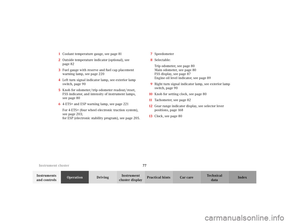
1
Coolant temperature gauge, see page 81
2 Outside temperature indicator (optional), see
page 82
3 Fuel gauge with reserve and fuel cap placement
warning lamp, see page 220
4 Left turn signal indicator lamp, see exterior lamp
switch, page 90
5 Knob for odometer / trip odometer readout / reset,
FSS indicator, and intensity of instrument lamps,
see page 80
6 4-ETS+ and ESP warning lamp, see page 221
For 4-ETS+ (four wheel electronic traction system),
see page 203;
for ESP (electronic stability program), see page 205. 7
Speedometer
8 Selectable:
Trip odometer, see page 80
Main odometer, see page 80
FSS display, see page 87
Engine oil level indicator, see page 89
9 Right turn signal indicator lamp, see exterior lamp
switch, page 90
10 Knob for setting clock, see page 80
11 Tachometer, see page 82
12 Gear range indicator display, see selector lever
positions, page 168
13 Clock, see page 80
Page 545 of 4133
78
Instrument cluster
Te ch n ica l
data
Instruments
and controls Operation
Driving Instrument
cluster display Practical hints Car care Index
Indicator lamps in the instrument cluster High beam
BAS malfunction, see page 221
ESP malfunction, see page 221
4-ETS+ malfunction, see page 221
ABS malfunction, see page 222
Brake pads worn down, see page 225
Engine oil level low, see page 224
Coolant level low, see page 224
Transmission in LOW RANGE mode,
see page 221 ESP and 4-ETS+. Adjust driving to road
condition, see page 221
Brake fluid low, see page 219
EBP malfunction, see page 204
Parking brake engaged, see page 173
Front passenger airbag automatically
switched off, see page 53
Front fog lamp, see page 92
Steering wheel adjustment not locked,
see page 70
Fasten seat belts,
see page 223
Battery not being charged properly,
see page 223
SRS malfunction, see page 219
BAS ESPABSLOW
RANGE
BRAKESRS
Page 583 of 4133
116
Interior equipment
Te ch n ica l
data
Instruments
and controls Operation
Driving Instrument
cluster display Practical hints Car care Index
Storage compartment under front passenger seat
(standard; optional on model ML 320)
The storage compartment under the front passenger
seat is lockable with its separate key (1).
Note:
Slide seat rearward to gain easier access to the storage
compartment. Cup holder in instrument panel
Touch top of cover. The cup holder (1) opens
automatically.
Caution!
Keep cup holder closed while traveling. Place only
containers that fit into the cup holder to prevent spills.
Do not fill containers to a height where the contents
could spill during vehicle maneuvers, especially hot
liquids.
Page 584 of 4133
117
Interior equipment
Te ch n ica l
data
Instruments
and controls Operation
Driving Instrument
cluster display Practical hints Car care Index
Cup holder in rear center console
To open cup holder (2), pull down at top of cover.
Caution!
Keep cup holder closed while traveling. Place only
containers that fit into the cup holder to prevent spills.
Do not fill containers to a height where the contents
could spill during vehicle maneuvers, especially hot
liquids. Armrest in rear bench seat
Pull down armrest (1) by its top.
Page 590 of 4133
123
Interior equipment
Te ch n ica l
data
Instruments
and controls Operation
Driving Instrument
cluster display Practical hints Car care Index
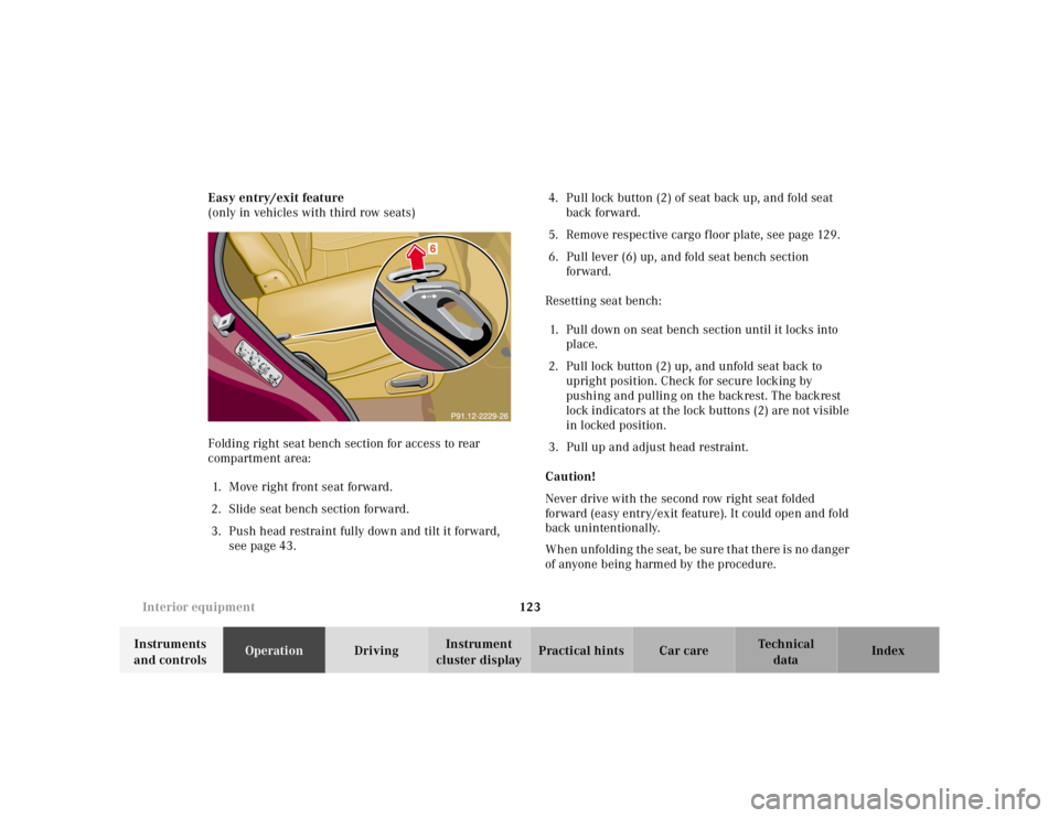
Easy entry/exit feature
(only in vehicles with third row seats)
Folding right seat bench section for access to rear
compartment area:
1. Move right front seat forward.
2. Slide seat bench section forward.
3. Push head restraint fully down and tilt it forward, see page 43. 4. Pull lock button (2) of seat back up, and fold seat
back forward.
5. Remove respective cargo floor plate, see page 129.
6. Pull lever (6) up, and fold seat bench section forward.
Resetting seat bench: 1. Pull down on seat bench section until it locks into place.
2. Pull lock button (2) up, and unfold seat back to upright position. Check for secure locking by
pushing and pulling on the backrest. The backrest
lock indicators at the lock buttons (2) are not visible
in locked position.
3. Pull up and adjust head restraint.
Caution!
Never drive with the second row right seat folded
forward (easy entry/exit feature). It could open and fold
back unintentionally.
When unfolding the seat, be sure that there is no danger
of anyone being harmed by the procedure.
Page 608 of 4133
141
Garage door opener
Te ch n ica l
data
Instruments
and controls Operation
Driving Instrument
cluster display Practical hints Car care Index
For operation in the USA only: This device complies
with Part 15, Subpart C, Section 209 of the FCC Rules.
Operation is subject to the following two conditions:
(1) This device may not cause harmful interference, and
(2) this device must accept any interference received,
including interference that may cause undesired
operation.
WARNING: Changes or modification not expressly
approved by party responsible for compliance could void
the user’s authority to operate the equipment.
Programming or reprogramming the integrated
remote control:
1. Turn key in steering lock to position 1 or 2.
2. Hold the end of the hand-held transmitter of the device you wish to train approximately 2 to 5 inches
(5 cm to 12 cm) away from the surface of the
integrated remote control located on the overhead
console, keeping the indicator lamp in view. 3. Using both hands, simultaneously push the hand-
held transmitter button and the desired integrated
remote control button. Do not release the buttons
until completing step 4.
4. The indicator lamp on the integrated remote control will flash, first slowly and then rapidly. When the
indicator lamp flashes rapidly, both buttons may be
released (the rapid flashing lamp indicates
successful programming of the new frequency
signal). To program the remaining two buttons,
follow ste ps 1 through 4.
Note:
If after repeated attempts, you do not successfully
program the integrated remote control device to learn
the signal of the hand-held transmitter, the garage door
opener could be equipped with the “rolling code
feature”.