1997 MERCEDES-BENZ ML430 low oil pressure
[x] Cancel search: low oil pressurePage 3484 of 4133

AH40.10-P-9411-01A
Information on tires/rims
Model 124, 129, 140, 163, 168, 169,
170, 171, 199, 201, 202, 203, 208, 209,
210, 211, 215, 219, 220, 230, 240, 414,
450, 452,
639
Tires
D
For service conversions, the tire/disc wheel specifications and
dimensions should be compared with the entries in the
registration papers.
D
When mounting tires, the tires and rims must be carefully
matched in order to guarantee the concentricity of the wheel.
Identification of matching points on:
- Tires with a colored dot on the outside of the tire,
- Sheet steel disk wheel by a colored dot or punch mark on the
outside of the wheel,
- Perform this operation at the valve stem hole on light-alloy
disk wheels
With an additional paint spot or punch mark in the rim base
for the 140 Model Series.
D
Always replace the rubber valve.
-----------------------------------------------------------------------------------------
D
Damaged and defective tires must always be replaced. The
repair methods employed in the tire trade are not approved by
Mercedes-Benz. Small nicks (<0.8mm) on the tire's sidewall do
not usually pose a cause for concern, and continued use of
such tires is approved
D When replacing just one tire, install it on the front of the vehicle.
This does not apply to vehicles with different tires of varying
specifications on the front and rear wheels.
D
Only use tires listed in the valid Service Information bulletins
and repair instructions.
D
If the permissible maximum speed of an M+S tire is below the
maximum speed of the vehicle, an appropriate adhesive plate
must be attached in the driver's field of view.
-----------------------------------------------------------------------------------------
D
Tires permissible for higher speeds may be used.
D
Always fit all rims with tires of the same design, make and
version.
-----------------------------------------------------------------------------------------
D
Run in new tires for approx. 100 km at moderate speed.
D
Handed tires must be installed according to the arrow on the
side wall of the tire.
D
Tires are subject to an aging process with negative effects on
the properties of the tire. In order to ensure optimum
effectiveness in winter, M+S tires should not be used for longer
than 3 years.
-----------------------------------------------------------------------------------------
Tire pressure
(For specified values see tire pressure table in the fuel filler flap, on
the Vaneo BM 414 see B-pillar on the passenger side).
Too low tire pressure increases the rolling resistance and increases
the flexing energy of the tire. This causes the critical temperature limit
to be exceeded (carcass detachment) and destroys the tire. Respond
to loss of tire pressure by determining the source and replacing the
tire as indicated.
Cleaning
Using a spray wand with high-pressure nozzles to clean the wheel
can lead to tire damage. Such damage occurs especially on the tire
side walls. The following should be observed when using flat jet
nozzles:
D
Maintain a minimum distance of 300 mm
D
Do not direct the water jet at a single point on the surface of the
tire for any length of time.
-----------------------------------------------------------------------------------------
Mounting in bearings
Before putting into storage, clean tires thoroughly and check for
damage and adequate tread depth. Mark the position and running
direction of the tires with chalk. Do not store tires outdoors. Under the
influence of sunlight, heat, moving air and ozone the rubber looses
elasticity and strength, ages more quickly and becomes cracked.
Storage areas should be dry, cool and dark. Avoid drafts by keeping
doors and windows closed as much as possible. Do not bring tires
into contact with gasoline, oil or other greases as they dissolve the
rubber.
Disposal
Collection, storage and disposal should be performed in accordance
with the legal requirements and the company's own regulations.
-----------------------------------------------------------------------------------------
Copyright DaimlerChrysler AG 06.07.2006 CD-Ausgabe G/10/04 . This WIS print-out will not be recorde
d by Modification services.
Page 1
Page 3752 of 4133
AR46.20-P-0600GH
Removing and installing rack-and-pinion steering
1.3.97
MODEL
163.113 /128 /136 /154 /157 /172 /174 /175
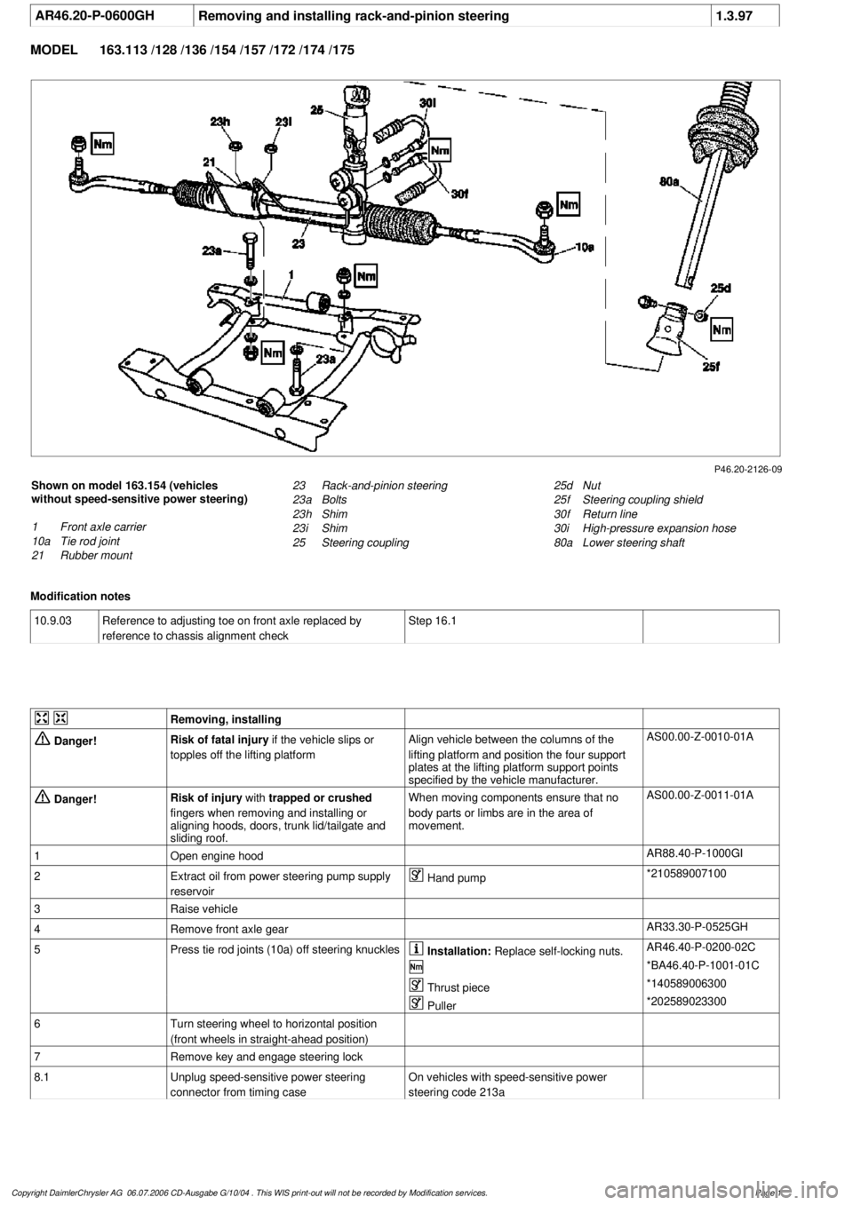
P46.20-2126-09
Shown on model 163.154 (vehicles
without speed-sensitive power steering)
1
Front axle carrier
10a
Tie rod joint
21
Rubber mount
25d
Nut
25f
Steering coupling shield
30f
Return line
30i
High-pressure expansion hose
80a
Lower steering shaft
23
Rack-and-pinion steering
23a
Bolts
23h
Shim
23i
Shim
25
Steering coupling
Modification notes
10.9.03
Reference to adjusting toe on front axle replaced by
reference to chassis alignment check
Step 16.1
Removing, installing
Danger!
Risk of fatal injury
if the vehicle slips or
topples off the lifting platform
Align vehicle between the columns of the
lifting platform and position the four support
plates
at the lifting platform support points
specified by the vehicle manufacturer.
AS00.00-Z-0010-01A
Danger!
Risk of injury
with
trapped or crushed
fingers when removing and installing or
aligning hoods, doors, trunk lid/tailgate and
sliding roof.
When moving components ensure that no
body parts or limbs are in the area of
movement.
AS00.00-Z-0011-01A
1
Open engine hood
AR88.40-P-1000GI
2
Extract oil from power steering pump supply
reservoir
Hand pump
*210589007100
3
Raise vehicle
4
Remove front axle gear
AR33.30-P-0525GH
5
Press tie rod joints (10a) off steering knuckles
Installation:
Replace self-locking nuts.
AR46.40-P-0200-02C
*BA46.40-P-1001-01C
Thrust piece
*140589006300
Puller
*202589023300
6
Turn steering wheel to horizontal position
(front wheels in straight-ahead position)
7
Remove key and engage steering lock
8.1
Unplug speed-sensitive power steering
connector from timing case
On vehicles with speed-sensitive power
steering code 213a
Copyright DaimlerChrysler AG 06.07.2006 CD-Ausgabe G/10/04 . This WIS print-out will not be recorde
d by Modification services.
Page 1
Page 3756 of 4133
AR20.20-P-3865HC
Remove/install the radiator
5.6.97
ENGINE
112.942 in MODEL 163.154
ENGINE
112.970 in MODEL 163.157
ENGINE
113.942 in MODEL 163.172
ENGINE
113.965 in MODEL 163.175
ENGINE
113.981 in MODEL 163.174
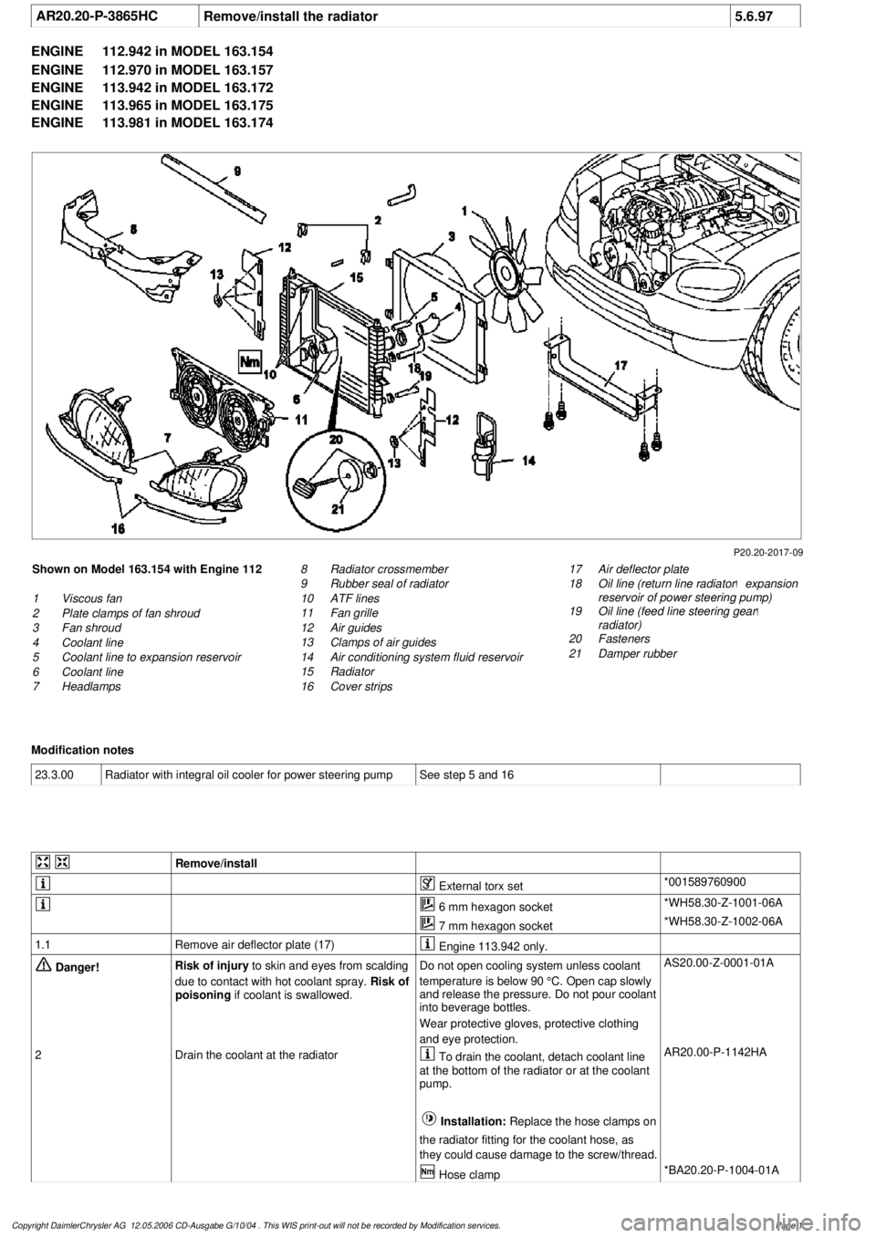
P20.20-2017-09
Shown on Model 163.154 with Engine 112
1
Viscous fan
2
Plate clamps of fan shroud
3
Fan shroud
4
Coolant line
5
Coolant line to expansion reservoir
6
Coolant line
7
Headlamps
17
Air deflector plate
18
Oil line (return line radiator
!
expansion
reservoir of power steering pump)
19
Oil line (feed line steering gear
!
radiator)
20
Fasteners
21
Damper rubber
8
Radiator crossmember
9
Rubber seal of radiator
10
ATF lines
11
Fan grille
12
Air guides
13
Clamps of air guides
14
Air conditioning system fluid reservoir
15
Radiator
16
Cover strips
Modification notes
23.3.00
Radiator with integral oil cooler for power steering pump
See step 5 and 16
Remove/install
External torx set
*001589760900
6 mm hexagon socket
*WH58.30-Z-1001-06A
7 mm hexagon socket
*WH58.30-Z-1002-06A
1.1
Remove air deflector plate (17)
Engine 113.942 only.
Danger!
Risk of injury
to skin and eyes from scalding
due to contact with hot coolant spray.
Risk of
poisoning
if coolant is swallowed.
Do not open cooling system unless coolant
temperature is below 90 °C. Open cap slowly
and release the pressure. Do not pour coolant
into beverage bottles.
Wear protective gloves, protective clothing
and eye protection.
AS20.00-Z-0001-01A
2
Drain the coolant at the radiator
To drain the coolant, detach coolant line
at the bottom of the radiator or at the coolant
pump.
Installation:
Replace the hose clamps on
the radiator fitting for the coolant hose, as
they could cause damage to the screw/thread. AR20.00-P-1142HA
Hose clamp
*BA20.20-P-1004-01A
Copyright DaimlerChrysler AG 12.05.2006 CD-Ausgabe G/10/04 . This WIS print-out will not be recorde
d by Modification services.
Page 1
Page 3761 of 4133

Danger!
Risk of injury
to skin and eyes suffering
scalding from contact with hot coolant spray.
Risk of poisoning
from swallowing coolant.
Do not open cooling system unless coolant
temperature is below 90 °C. Open cap slowly
and release the pressure. Do not pour coolant
into beverage bottles.
Wear protective gloves, protective clothing
and eye protection.
AS20.00-Z-0001-01A
1
Open engine hood and raise to vertical position
Have second person secure hood.
AR88.40-P-1000GI
2
Connect no load current retention unit
*WH58.30-Z-1005-09A
3
Disconnect battery ground cable
AR54.10-P-0003A
4
Remove trim panel of cylinder head cover
AR01.20-P-5014-02B
*BA01.20-P-1002-01A
*BA01.20-P-1003-01A
5
Remove bottom part of noise encapsulation
at front
AR94.30-P-5400GH
6
Remove electric fan (1)
Remove toward bottom.
AR20.40-P-5000M
7
Drain coolant
At radiator.
AR20.00-P-1142M
Notes on coolant
All engines
AH20.00-N-2080-01A
8
Remove charge air cooler (110/2)
AR09.41-P-6817MM
9.1
Attach guard plate for radiator/condenser
With automatic air conditioning, code
581a and AC system or Tempmatic USA,
code 580.
Attach additional AC condenser in the
vehicle.
y
Guard plate for radiator/condenser
Engine 606 in model 124,
Engine 606.961 in model 140,
Engine 112, 113, 604, 605, 611.960 in
MODEL 202,
Engine 602.983, 612.966 in MODEL 461,
Engine 628.962, 612.965, 606.964, 112.945,
113.962/ 982 in MODEL 463,
Engine 111, 112, 611.962, 612.962 in model
203,
Engines 112, 113, 611.961, 612.961, 613.961
in MODEL 210,
Engine 112 in model 170,
Engine 112 in MODEL 220,
Engine 113 in MODEL 211, 215, 220,
Engine 112 in MODEL 208,
Engine 112, 612.963, 628.963 in MODEL 163,
Engine 112.923 /943, 113.961 in MODEL 129,
Engine 137, 275 in MODEL 215, 220,
Engine 613.960, 628.960 in MODEL 220,
Engine 113.992 in model 230.474,
Engine 271 in model 209, 203,
Engine 285.950 in model 240.078 /178,
Engine 612.967 in model 209.316,
Engine 648 in model 220
Engine 112.951 in model 639.601/603/
605/701/703/705/801/803/805
Engine 646.983/984 in model 639.601/
603/605/701/703/705/801/803/805
Engine 646.982 in model
639.601/603/605/701/703/705
WF58.50-P-0110-01A
10
Remove seal rail (11)
11
Extract steering oil from reservoir
Hand pump
*210589007100
12.1
Disconnect power steering oil line (return line
radiator
!
power steering pump supply
reservoir) (18)
Seal connections.
Installation:
Install new sealing rings.
*BA46.30-P-1012-01A
Clamp
*000589543700
Set of stop plugs
*129589009100
12.2
Disconnect power steering oil line (feed line of
steering gear
!
radiator) (19)
Clamp
*000589543700
Set of stop plugs
*129589009100
Hexagon socket wrench
*WH58.30-Z-1001-06A
Hexagon socket wrench
*WH58.30-Z-1002-06A
Copyright DaimlerChrysler AG 12.05.2006 CD-Ausgabe G/10/04 . This WIS print-out will not be recorde
d by Modification services.
Page 2
Page 3771 of 4133
AR20.00-P-1250B
Remove oil from cooling and heating system
22.7.97
ENGINE
611.960 in MODEL 202.134 /193 /194 /133
ENGINE
611.961 in MODEL 210.006 /206 /007 /606
ENGINE
611.962 in MODEL 203.006 /004 /206 /204 /706
ENGINE
612.961 in MODEL 210.616 /216 /016
ENGINE
612.962 in MODEL 203.016 /216
ENGINE
612.963 in MODEL 163.113
ENGINE
613.960 in MODEL 220.026
ENGINE
613.961 in MODEL 210.026 /226
ENGINE
628.960 in MODEL 220.028 /128
ENGINE
628.961 in MODEL 211.028
ENGINE
628.963 in MODEL 163.128
ENGINE
646.951 in MODEL 211.004
ENGINE
646.961 in MODEL 211.006 /206 /606
ENGINE
647.961 in MODEL 211.016 /216 /616
ENGINE
648.961 in MODEL 211.023 /026 /223 /226
ENGINE
612.967 in MODEL 209.316
ENGINE
612.990 in MODEL 203.018 /218 /718
ENGINE
646.962 in MODEL 203.007 /207 /707
ENGINE
646.963 in MODEL 203.008 /208 /708
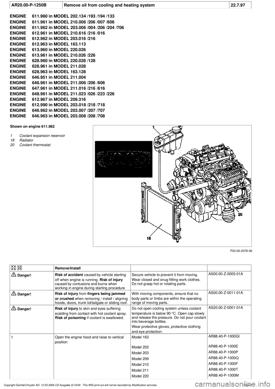
P20.00-2078-06
Shown on engine 611.962
1
Coolant expansion reservoir
18
Radiator
20
Coolant thermostat
Remove/Install
Danger!
Risk of accident
caused by vehicle starting
off when engine is running.
Risk of injury
caused by contusions and burns when
working in engine during starting procedure
Secure vehicle to prevent it from moving.
Wear closed and snug-fitting work clothes.
Do not grasp hot or rotating parts.
AS00.00-Z-0005-01A
Danger!
Risk of injury
from
fingers being jammed
or crushed
when removing / install / aligning
hoods, doors, trunk lid/tailgate or sliding roof.
With moving components, ensure that no
body parts or limbs are within the operating
range of moving parts.
AS00.00-Z-0011-01A
Danger!
Risk of injury
to skin and eyes suffering
scalding from contact with hot coolant spray.
Risk of poisoning
if coolant is swallowed.
Do not open cooling system unless coolant
temperature is below 90 °C. Open cap slowly
and release the pressure. Do not pour coolant
into beverage bottles.
Wear protective gloves, protective clothing
and eye protection.
AS20.00-Z-0001-01A
1
Open the engine hood and raise to vertical
position
Model 163
AR88.40-P-1000GI
Model 202
AR88.40-P-1000E
Model 203
AR88.40-P-1000P
Model 209
AR88.40-P-1000Q
Model 210
AR88.40-P-1000F
Model 211
AR88.40-P-1000T
Model 220
AR88.40-P-1000M
Copyright DaimlerChrysler AG 12.05.2006 CD-Ausgabe G/10/04 . This WIS print-out will not be recorde
d by Modification services.
Page 1
Page 3909 of 4133
1998-2005 SUSPENSION
Suspension - 163 Chassis
GENERAL INFORMATION
GENERAL NOTES ON WORKING ON VEHICLES WITH LEVEL CONTROL/ADS - AH32.00-P-0002-01A
All models with code 216b, 216c, 217a, 480
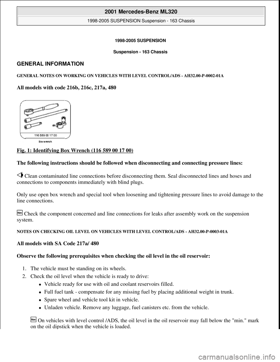
Fig. 1: Identifying Box Wrench (116 589 00 17 00)
The following instructions should be followed when disconnecting and connecting pressure lines:
Clean contaminated line connections before disconnecting them. Seal disconnected lines and hoses and
connections to components immediately with blind plugs.
Only use open box wrench and special tool when loosening and tightening pressure lines to avoid damage to the
line connections.
Check the component concerned and line connections for leaks after assembly work on the suspension
system.
NOTES ON CHECKING OIL LEVEL ON VEHICLES WITH LEVEL CONTROL/ADS - AH32.00-P-0003-01A
All models with SA Code 217a/ 480
Observe the following prerequisites when checking the oil level in the oil reservoir:
1. The vehicle must be standing on its wheels.
2. Check the oil level when the vehicle is ready to drive:
Vehicle ready for use with oil and coolant reservoirs filled.
Full fuel tank - compensate for any missing fuel by placing additional weight in trunk.
Spare wheel and vehicle tool kit in vehicle.
Unladen vehicle. Remove any luggage, fuel canisters etc. from the vehicle.
On vehicles with level control /ADS, the oil level in the oil reservoir may fall below the "min." mark
on the oil dipstick when the vehicle is loaded.
2001 Mercedes-Benz ML320
1998-2005 SUSPENSION Suspension - 163 Chassis
2001 Mercedes-Benz ML320
1998-2005 SUSPENSION Suspension - 163 Chassis
me
Saturday, October 02, 2010 3:37:35 PMPage 1 © 2006 Mitchell Repair Information Company, LLC.
me
Saturday, October 02, 2010 3:37:38 PMPage 1 © 2006 Mitchell Repair Information Company, LLC.
Page 3960 of 4133

AD54.30-P-5000-03A
Directly controlled display instruments
troubleshooting chart IC
Directly controlled display instruments or indicator
lamp/warning message:
D
Outside temperature indicator
D
Fuel gauge
D
Oil pressure gauge (models 129 and 140 only)
D
Left turn signal indicator lamp
D
Right turn signal indicator lamp
D
High beam indicator lamp
D
Fuel reserve indicator lamp
D
Airbag SRS indicator lamp/MIL
D
AIRBAG OFF indicator lamp (only model 163 except
I )
D
Low brake fluid level/parking brake indicator lamp (only brake
fluid direct)
(both functions via CAN on model 163)
D
Low windshield washer fluid level indicator lamp (except
models 163 and 168)
D
Low ECL indicator lamp (except models 163 and 168)
D
Generator charge indicator lamp
D
Seat belt reminder lamp
D
Seat belt/backrest lock reminder lamp
D
Exterior lamp failure indicator lamp
D
Hydraulic fluid level indicator lamp (models 202 and 210 only)
D
ADS MIL, suspension
D
Turn signal clicking
D
Seat belt reminder lamp
D
Light reminder lamp
D
Key reminder lamp
D
Soft top reminder lamp (model 170 only)
D
Steering lock warning lamp (
I )
Copyright DaimlerChrysler AG 05.06.2006 CD-Ausgabe G/10/04 . This WIS print-out will not be recorde
d by Modification services.
Page 1
Page 3994 of 4133
AP40.10-P-4050GH
Remove/install wheels, rotate if necessary
15.7.97
MODEL
163
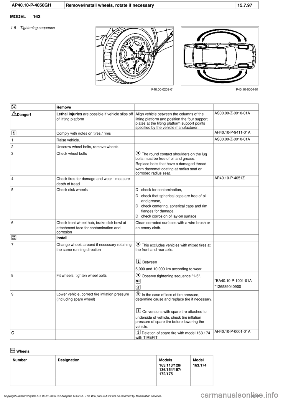
1-5
Tightening sequence
P40.10-0004-01
P40.00-0208-01
Remove
Danger!
Lethal injuries
are possible if vehicle slips off
of lifting platform
Align vehicle between the columns of the
lifting platform and position the four support
plates
at the lifting platform support points
specified by the vehicle manufacturer.
AS00.00-Z-0010-01A
Comply with notes on tires / rims
AH40.10-P-9411-01A
1
Raise vehicle.
AS00.00-Z-0010-01A
2
Unscrew wheel bolts, remove wheels
3
Check wheel bolts
The round contact shoulders on the lug
bolts must be free of oil and grease.
Replace bolts that have a damaged thread,
worn dacromet coating at radius seat or
corroded radius seat.
4
Check tires for damage and wear - measure
depth of tread
AP40.10-P-4051Z
5
Check disk wheels
D
check for contamination,
D
check that spherical caps are free of oil
and grease,
D
check centering, spherical caps and rim
flanges for damage,
D
check corrosion of lay-on surface
6
Check front wheel hub, brake disk bowl at
attachment face for contamination and
corrosion
Clean corroded surfaces with a wire brush or
an emery cloth.
Install
7
Change wheels around if necessary retaining
the same running direction
This excludes vehicles with mixed tires at
the front and rear axle.
Between
5,000 and 10,000 km according to wear.
8
Fit wheels, tighten wheel bolts
Observe tightening sequence "1-5".
*BA40.10-P-1001-01A
*126589040900
9
Lower vehicle, correct tire inflation pressure
(including spare wheel)
In the case of loss of tire pressure,
determine cause and replace tire if necessary.
On versions with spare tire attached to
underside of vehicle, check tire inflation
pressure of spare tire before lowering the
vehicle.
c
Deletion of spare tire with model 163.174
with TIREFIT
AH40.10-P-0001-01A
Wheels
Number
Designation
Models
163.113/128/
136/154/157/
172/175
Model
163.174
Copyright DaimlerChrysler AG 06.07.2006 CD-Ausgabe G/10/04 . This WIS print-out will not be recorde
d by Modification services.
Page 1