1997 MERCEDES-BENZ ML430 low oil pressure
[x] Cancel search: low oil pressurePage 3228 of 4133
A/C housing. Disconnect control module connector. To install reverse removal procedure. Recode 5-digit radio
security code. Using HHT, check for DTC and erase, and set clock.
A/C PUSH BUTTON CONTROL PANEL
Removal & Installation
1. Obtain 5-digit radio security code from vehicle owner. Disconnect negative battery cable. Using radio
removal plates, remove radio. Disconnect electrical connectors.
2. Remove instrument panel center section. Remove 4 A/C control panel screws and remove control panel.
Release pull cables and disconnect connectors. To install, reverse removal procedure. Recode radio. See
RECODING RADIO
under PROGRAMMING.
BLOWER MOTOR
Removal & Installation
Remove passenger-side instrument panel under cover. Remove blower motor mounting screws from A/C
housing unit. Disconnect blower motor connector and remove blower motor. To install, reverse removal
procedure.
COMPRESSOR
Removal & Installation
1. Discharge A/C system, using approved refrigerant recovery/recycling equipment. Remove accessory
drive belt. Disconnect low pressure refrigerant line from compressor. Discard "O" rings. Plug exposed
openings to protect A/C system from debris and moisture.
2. Disconnect high pressure refrigerant line from compressor. Discard "O" rings. Plug exposed openings to
protect A/C system from debris and moisture. Disconnect electrical connector. Remove compressor
mounting bolts.
3. Raise and support vehicle. Remove compressor from under vehicle without spilling refrigerant oil. To
install, reverse removal procedure. Ensure refrigerant oil quantity in compressor is correct. See
COMPRESSOR REFRIGERANT OIL CHECKING under GENERAL SERVICING. Tighten bolts to
specification. See TORQUE SPECIFICATIONS
.
CONDENSER
Removal & Installation
1. Discharge A/C system, using approved refrigerant recovery/recycling equipment. Remove cooling fans.
See COOLING FANS
. Disconnect refrigerant line from receiver-drier. See Fig. 5 . Discard "O" rings.
2. Plug exposed openings to protect A/C system from debris and moisture. Remove refrigerant line from
condenser. Remove radiator upper rubber seal. See Fig. 6
. Remove condenser upper mounting screws.
Lift condenser upward and remove. NOTE: Each time A/C compressor is removed and installed, receiver-drier must be
replaced.
2001 Mercedes-Benz ML320
2000-01 MANUAL A/C-HEATER SYSTEMS ML 320, ML 430 & ML 55
me
Saturday, October 02, 2010 3:25:10 PMPage 17 © 2006 Mitchell Repair Information Company, LLC.
Page 3369 of 4133
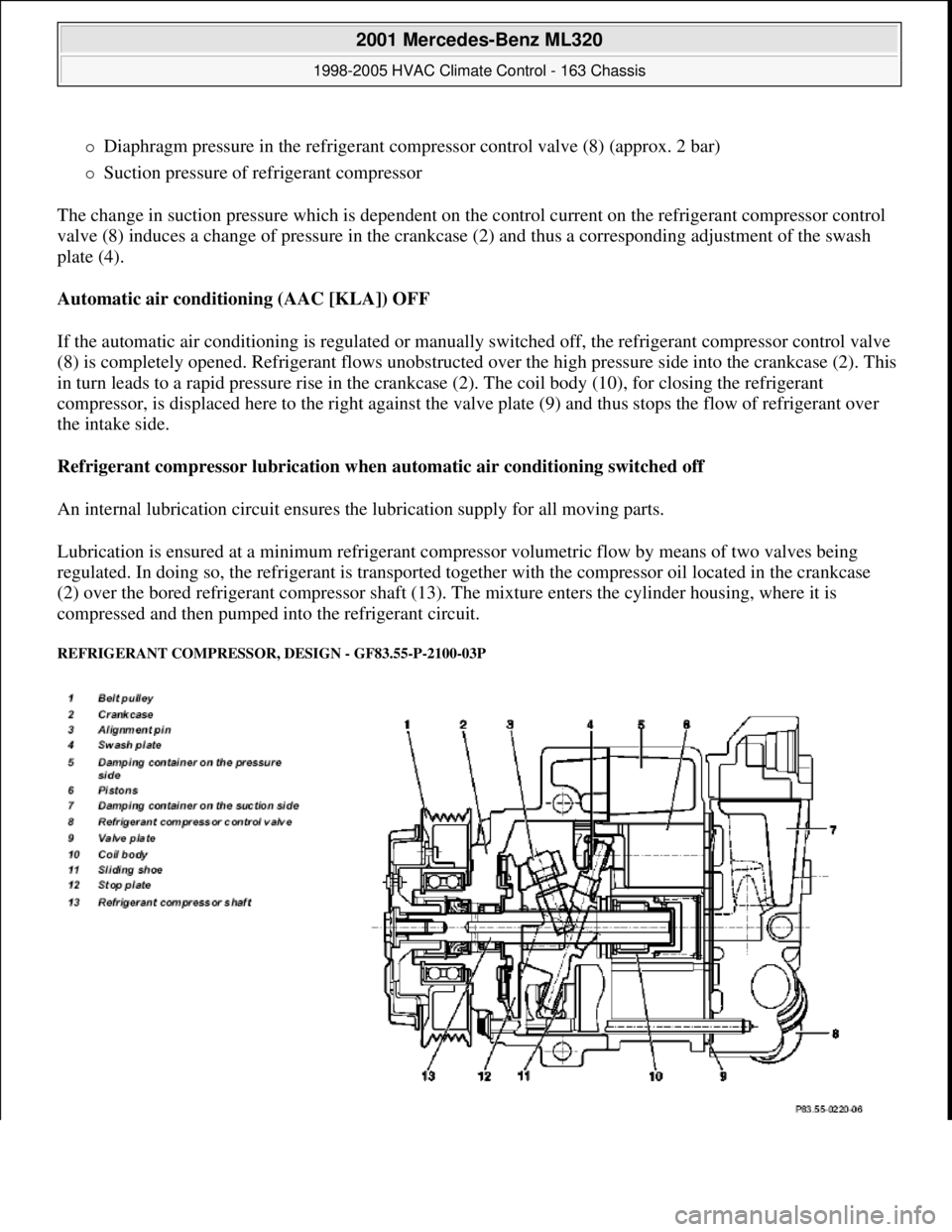
Diaphragm pressure in the refrigerant compressor control valve (8) (approx. 2 bar)
Suction pressure of refrigerant compressor
The change in suction pressure which is dependent on the control current on the refrigerant compressor control
valve (8) induces a change of pressure in the crankcase (2) and thus a corresponding adjustment of the swash
plate (4).
Automatic air conditioning (AAC [KLA]) OFF
If the automatic air conditioning is regulated or manually switched off, the refrigerant compressor control valve
(8) is completely opened. Refrigerant flows unobstructed over the high pressure side into the crankcase (2). This
in turn leads to a rapid pressure rise in the crankcase (2). The coil body (10), for closing the refrigerant
compressor, is displaced here to the right against the valve plate (9) and thus stops the flow of refrigerant over
the intake side.
Refrigerant compressor lubrication when automatic air conditioning switched off
An internal lubrication circuit ensures the lubrication supply for all moving parts.
Lubrication is ensured at a minimum refrigerant compressor volumetric flow by means of two valves being
regulated. In doing so, the refrigerant is transported together with the compressor oil located in the crankcase
(2) over the bored refrigerant compressor shaft (13). The mixture enters the cylinder housing, where it is
compressed and then pumped into the refrigerant circuit.
REFRIGERANT COMPRESSOR, DESIGN - GF83.55-P-2100-03P
2001 Mercedes-Benz ML320
1998-2005 HVAC Climate Control - 163 Chassis
me
Saturday, October 02, 2010 3:23:16 PMPage 125 © 2006 Mitchell Repair Information Company, LLC.
Page 3432 of 4133
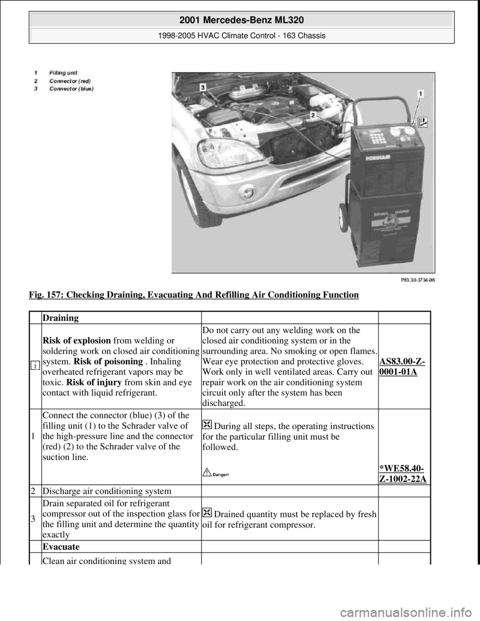
Fig. 157: Checking Draining, Evacuating And Refilling Air Conditioning Function
Draining
Risk of explosion from welding or
soldering work on closed air conditioning
system. Risk of poisoning . Inhaling
overheated refrigerant vapors may be
toxic. Risk of injury from skin and eye
contact with liquid refrigerant.
Do not carry out any welding work on the
closed air conditioning system or in the
surrounding area. No smoking or open flames.
Wear eye protection and protective gloves.
Work only in well ventilated areas. Carry out
repair work on the air conditioning system
circuit only after the system has been
discharged.
AS83.00-Z-
0001-01A
1
Connect the connector (blue) (3) of the
filling unit (1) to the Schrader valve of
the high-pressure line and the connector
(red) (2) to the Schrader valve of the
suction line.
During all steps, the operating instructions
for the particular filling unit must be
followed.
*WE58.40-
Z-1002-22A
2Discharge air conditioning system
3
Drain separated oil for refrigerant
compressor out of the inspection glass for
the filling unit and determine the quantity
exactly
Drained quantity must be replaced by fresh
oil for refrigerant compressor.
Evacuate
Clean air conditioning system and
2001 Mercedes-Benz ML320
1998-2005 HVAC Climate Control - 163 Chassis
me
Saturday, October 02, 2010 3:23:18 PMPage 188 © 2006 Mitchell Repair Information Company, LLC.
Page 3441 of 4133
poisoning from swallowing
coolant.Wear protective gloves, protective
clothing and eye protection.
1Drain coolantEngine 111 in MODEL 163.AR20.00-P-
1142HG
Engines 112 /113 in MODEL 163.AR20.00-
P-1142HA
Engine 628.963 in MODEL 163.128.AR20.00-P-
1142HB
Engine 612.963 in MODEL 163.113.AR20.00-P-
1142M
2.1 Detach
brake line
from the
front end of
the radiator
Only required for right-hand steering.
3.1 Detach
ignition
cable from
the front end
of the
radiator
Only required on right-hand drive vehicles
with ENGINES 111 /112/113.
4Release coolant overflow from
battery shield
5Disconnect upper coolant hose
from the electric coolant pump Detach hose clamp from the upper
coolant hose.
6Unscrew nuts from expansion
reservoir at firewall
7Remove expansion reservoir from
the firewall and lay aside
8Disconnect coolant delivery/return
hoses for heat exchanger (17) Detach hose clamps from coolant
delivery/ return hoses for heat exchanger.
9Discharge air conditioning system
Installation: Evacuate air
conditioning, refill and check for proper
operation and leaktightness.AR83.30-
P-1760GH
10Unscrew self-locking nut (16) at
the expansion valve (15) Replace self-locking nut.
*BA83.30-
P-1003-01B
11
Detach low-pressure refrigerant
line (13) and high-pressure
refrigerant line (14) from expansion
valve (15)
Installation: Install new sealing rings
and moisten with compressor oil.
12Remove instrument panel carrier
(4) AR68.10-
P-1111GH
2001 Mercedes-Benz ML320
1998-2005 HVAC Climate Control - 163 Chassis
me
Saturday, October 02, 2010 3:23:18 PMPage 197 © 2006 Mitchell Repair Information Company, LLC.
Page 3446 of 4133
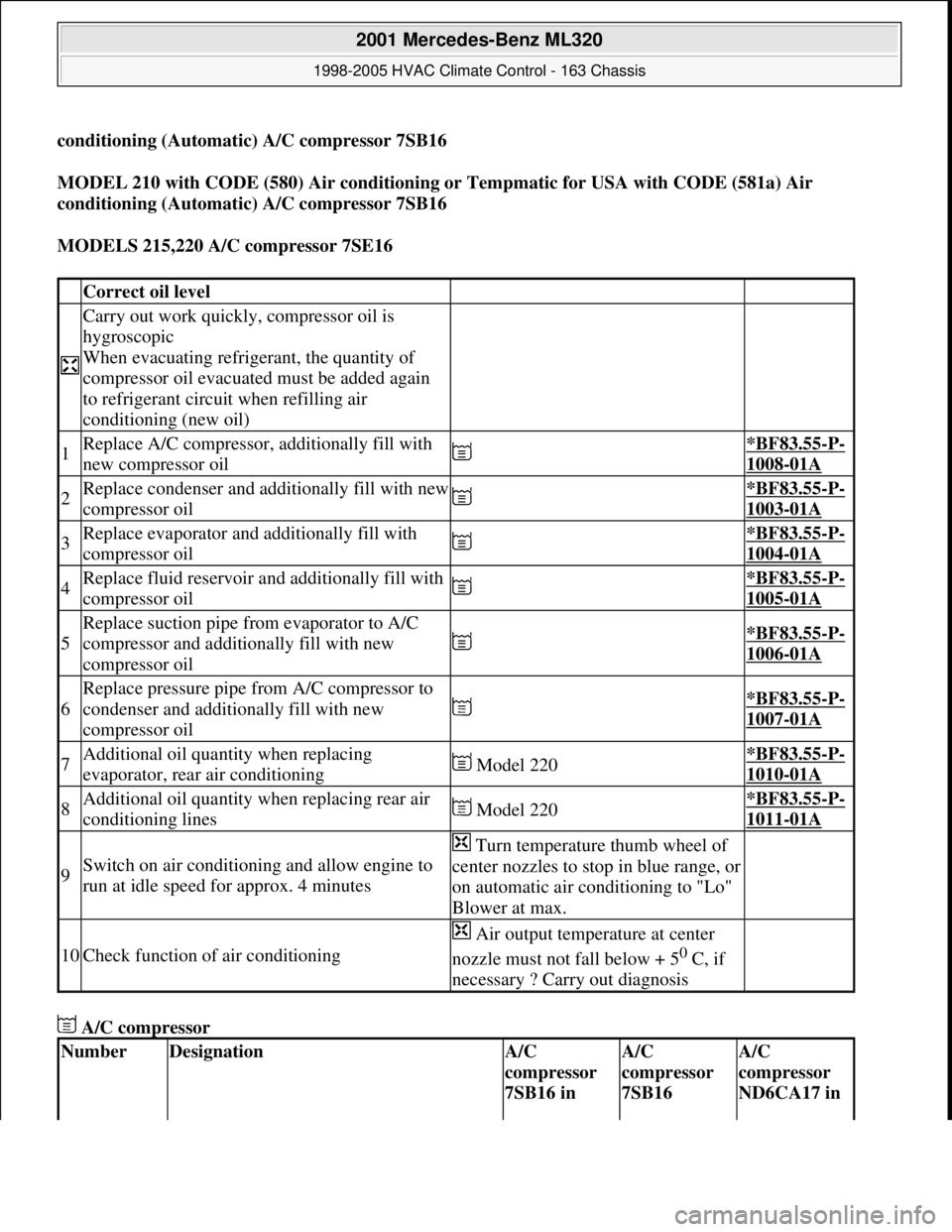
conditioning (Automatic) A/C compressor 7SB16
MODEL 210 with CODE (580) Air conditioning or Tempmatic for USA with CODE (581a) Air
conditioning (Automatic) A/C compressor 7SB16
MODELS 215,220 A/C compressor 7SE16
A/C compressor
Correct oil level
Carry out work quickly, compressor oil is
hygroscopic
When evacuating refrigerant, the quantity of
compressor oil evacuated must be added again
to refrigerant circuit when refilling air
conditioning (new oil)
1Replace A/C compressor, additionally fill with
new compressor oil *BF83.55-P-
1008-01A
2Replace condenser and additionally fill with new
compressor oil *BF83.55-P-
1003-01A
3Replace evaporator and additionally fill with
compressor oil *BF83.55-P-
1004-01A
4Replace fluid reservoir and additionally fill with
compressor oil *BF83.55-P-
1005-01A
5
Replace suction pipe from evaporator to A/C
compressor and additionally fill with new
compressor oil
*BF83.55-P-
1006-01A
6
Replace pressure pipe from A/C compressor to
condenser and additionally fill with new
compressor oil
*BF83.55-P-
1007-01A
7Additional oil quantity when replacing
evaporator, rear air conditioning Model 220*BF83.55-P-
1010-01A
8Additional oil quantity when replacing rear air
conditioning lines Model 220*BF83.55-P-
1011-01A
9Switch on air conditioning and allow engine to
run at idle speed for approx. 4 minutes
Turn temperature thumb wheel of
center nozzles to stop in blue range, or
on automatic air conditioning to "Lo"
Blower at max.
10Check function of air conditioning
Air output temperature at center
nozzle must not fall below + 5
0 C, if
necessary ? Carry out diagnosis
NumberDesignationA/C
compressor
7SB16 in A/C
compressor
7SB16 A/C
compressor
ND6CA17 in
2001 Mercedes-Benz ML320
1998-2005 HVAC Climate Control - 163 Chassis
me
Saturday, October 02, 2010 3:23:18 PMPage 202 © 2006 Mitchell Repair Information Company, LLC.
Page 3464 of 4133
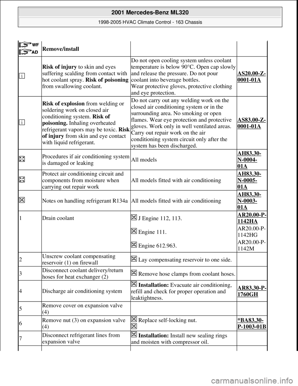
Remove/install
Risk of injury to skin and eyes
suffering scalding from contact with
hot coolant spray. Risk of poisoning
from swallowing coolant.
Do not open cooling system unless coolant
temperature is below 90°C. Open cap slowly
and release the pressure. Do not pour
coolant into beverage bottles.
Wear protective gloves, protective clothing
and eye protection.
AS20.00-Z-
0001-01A
Risk of explosion from welding or
soldering work on closed air
conditioning system. Risk of
poisoning. Inhaling overheated
refrigerant vapors may be toxic. Risk
of injury from skin and eye contact
with liquid refrigerant.Do not carry out any welding work on the
closed air conditioning system or in the
surrounding area. No smoking or open
flames. Wear eye protection and protective
gloves. Work only in well ventilated areas.
Carry out repair work on the air
conditioning system circuit only after the
system has been discharged.
AS83.00-Z-
0001-01A
Procedures if air conditioning system
is damaged or leakingAll models
AH83.30-
N-0004-
01A
Protect air conditioning circuit and
components from moisture when
carrying out repair work
All models fitted with air conditioning
AH83.30-
N-0005-
01A
Notes on handling refrigerant R134aAll models fitted with air conditioning
AH83.30-
N-0003-
01A
1Drain coolant J Engine 112, 113.AR20.00-P-
1142HA
Engine 111.AR20.00-P-
1142HG
Engine 612.963.AR20.00-P-
1142M
2Unscrew coolant compensating
reservoir (1) on firewall Lay compensating reservoir to one side.
3Disconnect coolant delivery/return
hoses for heat exchanger (2) Remove hose clamps from coolant hoses.
4Discharge air conditioning system
Installation: Evacuate air conditioning,
refill and check for proper operation and
leaktightness.AR83.30-P-
1760GH
5Remove cover on expansion valve
(4)
6Remove nut (3) on expansion valve
(4) Replace self-locking nut.
*BA83.30-
P-1003-01B
7Disconnect refrigerant lines from
expansion valve Installation: Install new sealing rings
and moisten with compressor oil.
2001 Mercedes-Benz ML320
1998-2005 HVAC Climate Control - 163 Chassis
me
Saturday, October 02, 2010 3:23:19 PMPage 220 © 2006 Mitchell Repair Information Company, LLC.
Page 3473 of 4133
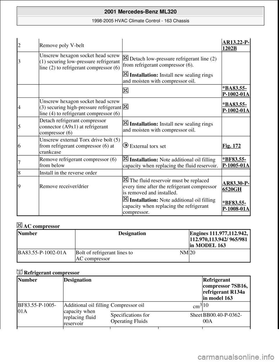
AC compressor
Refrigerant compressor
2Remove poly V-belt AR13.22-P-
1202B
3
Unscrew hexagon socket head screw
(1) securing low-pressure refrigerant
line (2) to refrigerant compressor (6) Detach low-pressure refrigerant line (2)
from refrigerant compressor (6).
Installation: Install new sealing rings
and moisten with compressor oil.
*BA83.55-
P-1002-01A
4
Unscrew hexagon socket head screw
(3) securing high-pressure refrigerant
line (4) to refrigerant compressor (6)
*BA83.55-
P-1002-01A
5
Detach refrigerant compressor
connector (A9x1) at refrigerant
compressor (6) Installation: Install new sealing rings
and moisten with compressor oil.
6
Unscrew external Torx drive bolt (5)
from refrigerant compressor (6) at
crankcase
External torx setFig. 172
7Remove refrigerant compressor (6)
from below Installation: Note additional oil filling
capacity when replacing the fluid reservoir.*BF83.55-
P-1005-01A
8Install in the reverse order
9Remove receiver/drier
The fluid reservoir must be replaced
every time after the refrigerant compressor
is removed and installed.AR83.30-P-
6520GH
Installation: Note additional oil filling
capacity when replacing the refrigerant
compressor.*BF83.55-
P-1008-01A
NumberDesignationEngines 111.977,112.942,
112.970,113.942/ 965/981
in MODEL 163
BA83.55-P-1002-01ABolt of refrigerant lines to
AC compressorNM20
NumberDesignationRefrigerant
compressor 7SB16,
refrigerant R134a
in model 163
BF83.55-P-1005-
01AAdditional oil filling
capacity when
replacing fluid
reservoirCompressor oilcm3 10
Specifications for
Operating FluidsSheetBB00.40-P-0362-
00A
2001 Mercedes-Benz ML320
1998-2005 HVAC Climate Control - 163 Chassis
me
Saturday, October 02, 2010 3:23:19 PMPage 229 © 2006 Mitchell Repair Information Company, LLC.
Page 3479 of 4133

BT27.00-Z-9999AZ
Technical modifications: Passenger cars: Automatic transmission
30.4.97
MODEL all
Vacuum unit for modulating pressure modified
TRANSMISSION 722.3 /5 as of 15.8.92
BT27.10-P-0001-01A
Secondary pump dispensed with
TRANSMISSION 722.5## ## as of 3652931
BT27.10-P-0002-01A
Control pressure cable with vacuum actuators
standardized
TRANSMISSION 722.3 /4 /5 as of 1.7.93
BT27.10-P-0003-01A
Sump volume modified
TRANSMISSION 722.7## ## as of 0054011
as of 29.7.99
BT27.10-P-0004-01A
Additional shim between deep-groove ball
bearing and output flange
TRANSMISSION 722 ...
BT27.10-P-0005-01A
Oil pan and overflow tube modified
TRANSMISSION 722.901
BT27.10-P-0006-01W
Retaining lug added to electrohydraulic
control module
TRANSMISSION 722.6## # as of 0026195
BT27.19-P-0001-01A
Caps for solenoid valve, new
TRANSMISSION 722.6 as of 1.8.97
BT27.19-P-0003-01A
Oil drain plug on torque converter deleted
TRANSMISSION 722.6## /6## ## as of
1772285 as of 22.9.99
BT27.20-P-0001-01A
Small intermediate plate modified
TRANSMISSION 722.5## ## as of 3987361
as of 15.3.94
BT27.35-P-0001-01A
Installation of a pressure feed valve
TRANSMISSION 722.6## # as of 0027083
BT27.35-P-0002-01A
Primary pump non-return valve dispensed with
TRANSMISSION 722.5## ## as of 3652931
BT27.35-P-0003-01A
Strainer for modulating pressure and shift
pressure control solenoid valve, new
TRANSMISSION 722.6## ## as of 0538312
BT27.35-P-0004-01A
Strainer in inlet to converter lock-up control
solenoid valve, newTRANSMISSION 722.6## ## as of 0485895
BT27.35-P-0005-01A
Feed B1 enlarged
TRANSMISSION 722.5 as of 15.8.91
BT27.40-P-0001-01A
Fluid reservoir deleted
TRANSMISSION 722.7## ## as of 0111673
as of 11.9.00
BT27.40-P-0002-01A
Magnet in oil pan, new part
TRANSMISSION 722.6## ## as of 2871384
as of 17.4.01, 722.7## ## as of 0153700 as
of 9.7.01
BT27.40-P-0003-01A
Piston B1 modified
TRANSMISSION 722.5## ## as of 3746852
as of 15.6.92, 722.3## ## as of 3969172
BT27.50-P-0002-01A
Plain bearing of input shaft changed to an anti-
friction bearing
TRANSMISSION 722 ...
BT27.50-P-0002-02A
One-way valve dispensed with
TRANSMISSION 722.5## ## as of 3652931
BT27.50-P-0007-01A
Outer multiple-disc carrier B1 modified
TRANSMISSION 722.6## # as of 0005900
BT27.50-P-0008-01A
Peak-to-valley height on piston B2 modified
TRANSMISSION 722.6## # as of 0023104
BT27.50-P-0009-01A
Piston B2 changed
TRANSMISSION 722.6## ## as of 0552036
as of 1.8.97
BT27.50-P-0010-01A
Friction bearing in sun wheel of rear planet
gear set converted to anti-friction bearing
TRANSMISSION 722 ...
BT27.50-P-0011-01A
Conversion from 18° to 23° gearing in front
and rear planetary gear system
TRANSMISSION 722 ...
BT27.50-P-0012-01A
Multi-disks for B1, K1 and K3 changed
TRANSMISSION 722.6## ## as of 3947440
as of 2.9.02
BT27.50-P-0013-01A
Thickness of friction and steel disks K3
changed
TRANSMISSION 722.6
BT27.51-P-0001-01A
Thickness of steel plates of B1, K1 and K2
modified
TRANSMISSION 722.6## ## as of 1596205
as of 15.6.99
BT27.51-P-0002-01A
Additional dished washer in multi-plate set K2
TRANSMISSION 722.6## ## as of 1596205
as of 15.6.99
BT27.51-P-0003-01A
Center shift modified
TRANSMISSION 722.6
BT27.60-P-0001-01A
Deletion shift lock cable ignition lock to
transmission
TRANSMISSION 722.7 in MODEL
WDB168.### ## as of 548031 as of 10.1.01
BT27.60-P-0001-02A
Selector lever soldered
TRANSMISSION 722.6 as of 1.5.96
BT27.60-P-0002-01A
Deletion of lever for shift lock cable ignition
lock at transmission
TRANSMISSION 722.700 ## as of 0129631
as of 24.1.01, 722.701 ## as of 0132072 as
of 8.2.01
BT27.60-P-0003-01A
Copyright DaimlerChrysler AG 28.05.2006 CD-Ausgabe G/10/04 . This WIS print-out will not be recorde
d by Modification services.
Page 1