1997 MERCEDES-BENZ ML430 Oil pressure valve
[x] Cancel search: Oil pressure valvePage 3441 of 4133
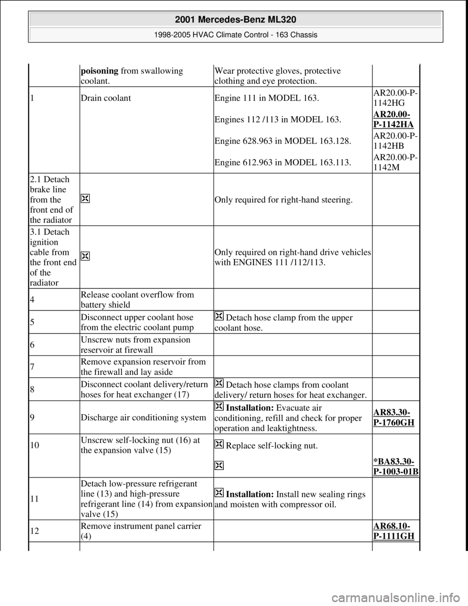
poisoning from swallowing
coolant.Wear protective gloves, protective
clothing and eye protection.
1Drain coolantEngine 111 in MODEL 163.AR20.00-P-
1142HG
Engines 112 /113 in MODEL 163.AR20.00-
P-1142HA
Engine 628.963 in MODEL 163.128.AR20.00-P-
1142HB
Engine 612.963 in MODEL 163.113.AR20.00-P-
1142M
2.1 Detach
brake line
from the
front end of
the radiator
Only required for right-hand steering.
3.1 Detach
ignition
cable from
the front end
of the
radiator
Only required on right-hand drive vehicles
with ENGINES 111 /112/113.
4Release coolant overflow from
battery shield
5Disconnect upper coolant hose
from the electric coolant pump Detach hose clamp from the upper
coolant hose.
6Unscrew nuts from expansion
reservoir at firewall
7Remove expansion reservoir from
the firewall and lay aside
8Disconnect coolant delivery/return
hoses for heat exchanger (17) Detach hose clamps from coolant
delivery/ return hoses for heat exchanger.
9Discharge air conditioning system
Installation: Evacuate air
conditioning, refill and check for proper
operation and leaktightness.AR83.30-
P-1760GH
10Unscrew self-locking nut (16) at
the expansion valve (15) Replace self-locking nut.
*BA83.30-
P-1003-01B
11
Detach low-pressure refrigerant
line (13) and high-pressure
refrigerant line (14) from expansion
valve (15)
Installation: Install new sealing rings
and moisten with compressor oil.
12Remove instrument panel carrier
(4) AR68.10-
P-1111GH
2001 Mercedes-Benz ML320
1998-2005 HVAC Climate Control - 163 Chassis
me
Saturday, October 02, 2010 3:23:18 PMPage 197 © 2006 Mitchell Repair Information Company, LLC.
Page 3464 of 4133
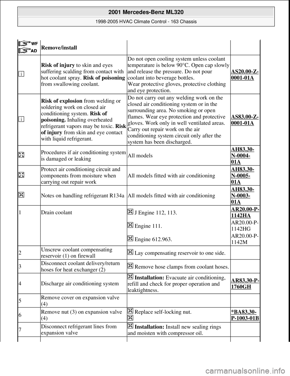
Remove/install
Risk of injury to skin and eyes
suffering scalding from contact with
hot coolant spray. Risk of poisoning
from swallowing coolant.
Do not open cooling system unless coolant
temperature is below 90°C. Open cap slowly
and release the pressure. Do not pour
coolant into beverage bottles.
Wear protective gloves, protective clothing
and eye protection.
AS20.00-Z-
0001-01A
Risk of explosion from welding or
soldering work on closed air
conditioning system. Risk of
poisoning. Inhaling overheated
refrigerant vapors may be toxic. Risk
of injury from skin and eye contact
with liquid refrigerant.Do not carry out any welding work on the
closed air conditioning system or in the
surrounding area. No smoking or open
flames. Wear eye protection and protective
gloves. Work only in well ventilated areas.
Carry out repair work on the air
conditioning system circuit only after the
system has been discharged.
AS83.00-Z-
0001-01A
Procedures if air conditioning system
is damaged or leakingAll models
AH83.30-
N-0004-
01A
Protect air conditioning circuit and
components from moisture when
carrying out repair work
All models fitted with air conditioning
AH83.30-
N-0005-
01A
Notes on handling refrigerant R134aAll models fitted with air conditioning
AH83.30-
N-0003-
01A
1Drain coolant J Engine 112, 113.AR20.00-P-
1142HA
Engine 111.AR20.00-P-
1142HG
Engine 612.963.AR20.00-P-
1142M
2Unscrew coolant compensating
reservoir (1) on firewall Lay compensating reservoir to one side.
3Disconnect coolant delivery/return
hoses for heat exchanger (2) Remove hose clamps from coolant hoses.
4Discharge air conditioning system
Installation: Evacuate air conditioning,
refill and check for proper operation and
leaktightness.AR83.30-P-
1760GH
5Remove cover on expansion valve
(4)
6Remove nut (3) on expansion valve
(4) Replace self-locking nut.
*BA83.30-
P-1003-01B
7Disconnect refrigerant lines from
expansion valve Installation: Install new sealing rings
and moisten with compressor oil.
2001 Mercedes-Benz ML320
1998-2005 HVAC Climate Control - 163 Chassis
me
Saturday, October 02, 2010 3:23:19 PMPage 220 © 2006 Mitchell Repair Information Company, LLC.
Page 3479 of 4133

BT27.00-Z-9999AZ
Technical modifications: Passenger cars: Automatic transmission
30.4.97
MODEL all
Vacuum unit for modulating pressure modified
TRANSMISSION 722.3 /5 as of 15.8.92
BT27.10-P-0001-01A
Secondary pump dispensed with
TRANSMISSION 722.5## ## as of 3652931
BT27.10-P-0002-01A
Control pressure cable with vacuum actuators
standardized
TRANSMISSION 722.3 /4 /5 as of 1.7.93
BT27.10-P-0003-01A
Sump volume modified
TRANSMISSION 722.7## ## as of 0054011
as of 29.7.99
BT27.10-P-0004-01A
Additional shim between deep-groove ball
bearing and output flange
TRANSMISSION 722 ...
BT27.10-P-0005-01A
Oil pan and overflow tube modified
TRANSMISSION 722.901
BT27.10-P-0006-01W
Retaining lug added to electrohydraulic
control module
TRANSMISSION 722.6## # as of 0026195
BT27.19-P-0001-01A
Caps for solenoid valve, new
TRANSMISSION 722.6 as of 1.8.97
BT27.19-P-0003-01A
Oil drain plug on torque converter deleted
TRANSMISSION 722.6## /6## ## as of
1772285 as of 22.9.99
BT27.20-P-0001-01A
Small intermediate plate modified
TRANSMISSION 722.5## ## as of 3987361
as of 15.3.94
BT27.35-P-0001-01A
Installation of a pressure feed valve
TRANSMISSION 722.6## # as of 0027083
BT27.35-P-0002-01A
Primary pump non-return valve dispensed with
TRANSMISSION 722.5## ## as of 3652931
BT27.35-P-0003-01A
Strainer for modulating pressure and shift
pressure control solenoid valve, new
TRANSMISSION 722.6## ## as of 0538312
BT27.35-P-0004-01A
Strainer in inlet to converter lock-up control
solenoid valve, newTRANSMISSION 722.6## ## as of 0485895
BT27.35-P-0005-01A
Feed B1 enlarged
TRANSMISSION 722.5 as of 15.8.91
BT27.40-P-0001-01A
Fluid reservoir deleted
TRANSMISSION 722.7## ## as of 0111673
as of 11.9.00
BT27.40-P-0002-01A
Magnet in oil pan, new part
TRANSMISSION 722.6## ## as of 2871384
as of 17.4.01, 722.7## ## as of 0153700 as
of 9.7.01
BT27.40-P-0003-01A
Piston B1 modified
TRANSMISSION 722.5## ## as of 3746852
as of 15.6.92, 722.3## ## as of 3969172
BT27.50-P-0002-01A
Plain bearing of input shaft changed to an anti-
friction bearing
TRANSMISSION 722 ...
BT27.50-P-0002-02A
One-way valve dispensed with
TRANSMISSION 722.5## ## as of 3652931
BT27.50-P-0007-01A
Outer multiple-disc carrier B1 modified
TRANSMISSION 722.6## # as of 0005900
BT27.50-P-0008-01A
Peak-to-valley height on piston B2 modified
TRANSMISSION 722.6## # as of 0023104
BT27.50-P-0009-01A
Piston B2 changed
TRANSMISSION 722.6## ## as of 0552036
as of 1.8.97
BT27.50-P-0010-01A
Friction bearing in sun wheel of rear planet
gear set converted to anti-friction bearing
TRANSMISSION 722 ...
BT27.50-P-0011-01A
Conversion from 18° to 23° gearing in front
and rear planetary gear system
TRANSMISSION 722 ...
BT27.50-P-0012-01A
Multi-disks for B1, K1 and K3 changed
TRANSMISSION 722.6## ## as of 3947440
as of 2.9.02
BT27.50-P-0013-01A
Thickness of friction and steel disks K3
changed
TRANSMISSION 722.6
BT27.51-P-0001-01A
Thickness of steel plates of B1, K1 and K2
modified
TRANSMISSION 722.6## ## as of 1596205
as of 15.6.99
BT27.51-P-0002-01A
Additional dished washer in multi-plate set K2
TRANSMISSION 722.6## ## as of 1596205
as of 15.6.99
BT27.51-P-0003-01A
Center shift modified
TRANSMISSION 722.6
BT27.60-P-0001-01A
Deletion shift lock cable ignition lock to
transmission
TRANSMISSION 722.7 in MODEL
WDB168.### ## as of 548031 as of 10.1.01
BT27.60-P-0001-02A
Selector lever soldered
TRANSMISSION 722.6 as of 1.5.96
BT27.60-P-0002-01A
Deletion of lever for shift lock cable ignition
lock at transmission
TRANSMISSION 722.700 ## as of 0129631
as of 24.1.01, 722.701 ## as of 0132072 as
of 8.2.01
BT27.60-P-0003-01A
Copyright DaimlerChrysler AG 28.05.2006 CD-Ausgabe G/10/04 . This WIS print-out will not be recorde
d by Modification services.
Page 1
Page 3484 of 4133

AH40.10-P-9411-01A
Information on tires/rims
Model 124, 129, 140, 163, 168, 169,
170, 171, 199, 201, 202, 203, 208, 209,
210, 211, 215, 219, 220, 230, 240, 414,
450, 452,
639
Tires
D
For service conversions, the tire/disc wheel specifications and
dimensions should be compared with the entries in the
registration papers.
D
When mounting tires, the tires and rims must be carefully
matched in order to guarantee the concentricity of the wheel.
Identification of matching points on:
- Tires with a colored dot on the outside of the tire,
- Sheet steel disk wheel by a colored dot or punch mark on the
outside of the wheel,
- Perform this operation at the valve stem hole on light-alloy
disk wheels
With an additional paint spot or punch mark in the rim base
for the 140 Model Series.
D
Always replace the rubber valve.
-----------------------------------------------------------------------------------------
D
Damaged and defective tires must always be replaced. The
repair methods employed in the tire trade are not approved by
Mercedes-Benz. Small nicks (<0.8mm) on the tire's sidewall do
not usually pose a cause for concern, and continued use of
such tires is approved
D When replacing just one tire, install it on the front of the vehicle.
This does not apply to vehicles with different tires of varying
specifications on the front and rear wheels.
D
Only use tires listed in the valid Service Information bulletins
and repair instructions.
D
If the permissible maximum speed of an M+S tire is below the
maximum speed of the vehicle, an appropriate adhesive plate
must be attached in the driver's field of view.
-----------------------------------------------------------------------------------------
D
Tires permissible for higher speeds may be used.
D
Always fit all rims with tires of the same design, make and
version.
-----------------------------------------------------------------------------------------
D
Run in new tires for approx. 100 km at moderate speed.
D
Handed tires must be installed according to the arrow on the
side wall of the tire.
D
Tires are subject to an aging process with negative effects on
the properties of the tire. In order to ensure optimum
effectiveness in winter, M+S tires should not be used for longer
than 3 years.
-----------------------------------------------------------------------------------------
Tire pressure
(For specified values see tire pressure table in the fuel filler flap, on
the Vaneo BM 414 see B-pillar on the passenger side).
Too low tire pressure increases the rolling resistance and increases
the flexing energy of the tire. This causes the critical temperature limit
to be exceeded (carcass detachment) and destroys the tire. Respond
to loss of tire pressure by determining the source and replacing the
tire as indicated.
Cleaning
Using a spray wand with high-pressure nozzles to clean the wheel
can lead to tire damage. Such damage occurs especially on the tire
side walls. The following should be observed when using flat jet
nozzles:
D
Maintain a minimum distance of 300 mm
D
Do not direct the water jet at a single point on the surface of the
tire for any length of time.
-----------------------------------------------------------------------------------------
Mounting in bearings
Before putting into storage, clean tires thoroughly and check for
damage and adequate tread depth. Mark the position and running
direction of the tires with chalk. Do not store tires outdoors. Under the
influence of sunlight, heat, moving air and ozone the rubber looses
elasticity and strength, ages more quickly and becomes cracked.
Storage areas should be dry, cool and dark. Avoid drafts by keeping
doors and windows closed as much as possible. Do not bring tires
into contact with gasoline, oil or other greases as they dissolve the
rubber.
Disposal
Collection, storage and disposal should be performed in accordance
with the legal requirements and the company's own regulations.
-----------------------------------------------------------------------------------------
Copyright DaimlerChrysler AG 06.07.2006 CD-Ausgabe G/10/04 . This WIS print-out will not be recorde
d by Modification services.
Page 1