1997 MERCEDES-BENZ ML430 cruise control
[x] Cancel search: cruise controlPage 2655 of 4133
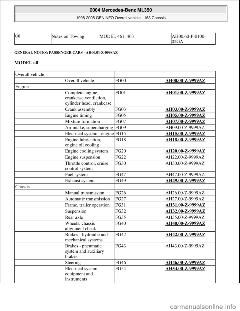
GENERAL NOTES: PASSENGER CARS - AH00.01-Z-0998AZ
MODEL all
Notes on TowingMODEL 461, 463AH00.60-P-0100-
02GA
Overall vehicle
Overall vehicleFG00AH00.00-Z-9999AZ
Engine
Complete engine,
crankcase ventilation,
cylinder head, crankcaseFG01AH01.00-Z-9999AZ
Crank assemblyFG03AH03.00-Z-9999AZ
Engine timingFG05AH05.00-Z-9999AZ
Mixture formationFG07AH07.00-Z-9999AZ
Air intake, superchargingFG09AH09.00-Z-9999AZ
Electrical system - engineFG15AH15.00-Z-9999AZ
Engine lubrication,
engine oil coolingFG18AH18.00-Z-9999AZ
Engine cooling systemFG20AH20.00-Z-9999AZ
Engine suspensionFG22AH22.00-Z-9999AZ
Throttle control, cruise
control systemFG30AH30.00-Z-9999AZ
Fuel systemFG47AH47.00-Z-9999AZ
Exhaust systemFG49AH49.00-Z-9999AZ
Chassis
Manual transmissionFG26AH26.00-Z-9999AZ
Automatic transmissionFG27AH27.00-Z-9999AZ
Frame, trailer operationFG31AH31.00-Z-9999AZ
SuspensionFG32AH32.00-Z-9999AZ
Rear axleFG35AH35.00-Z-9999AZ
Wheels, chassis
alignment checkFG40AH40.00-Z-9999AZ
Brakes - hydraulic and
mechanical systemsFG42AH42.00-Z-9999AZ
Brakes - pneumatic
system and auxiliary
brakesFG43AH43.00-Z-9999AZ
SteeringFG46AH46.00-Z-9999AZ
Electrical system,
equipment and
instrumentsFG54AH54.00-Z-9999AZ
2004 Mercedes-Benz ML350
1998-2005 GENINFO Overall vehicle - 163 Chassis
me
Saturday, October 02, 2010 3:47:44 PMPage 10 © 2006 Mitchell Repair Information Company, LLC.
Page 2851 of 4133
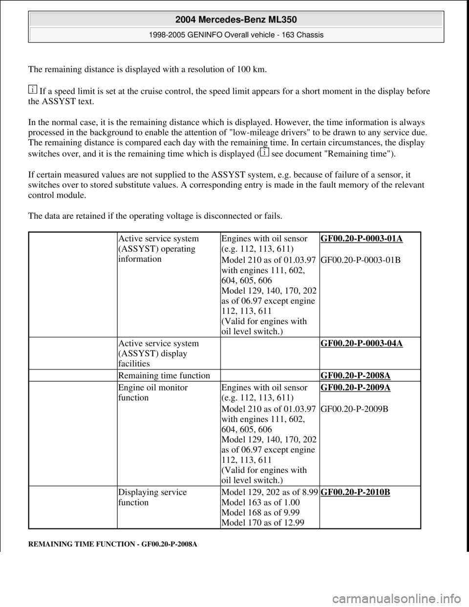
The remaining distance is displayed with a resolution of 100 km.
If a speed limit is set at the cruise control, the speed limit appears for a short moment in the display before
the ASSYST text.
In the normal case, it is the remaining distance which is displayed. However, the time information is always
processed in the background to enable the attention of "low-mileage drivers" to be drawn to any service due.
The remaining distance is compared each day with the remaining time. In certain circumstances, the display
switches over, and it is the remaining time which is displayed ( see document "Remaining time").
If certain measured values are not supplied to the ASSYST system, e.g. because of failure of a sensor, it
switches over to stored substitute values. A corresponding entry is made in the fault memory of the relevant
control module.
The data are retained if the operating voltage is disconnected or fails.
REMAINING TIME FUNCTION - GF00.20-P-2008A
Active service system
(ASSYST) operating
informationEngines with oil sensor
(e.g. 112, 113, 611)GF00.20-P-0003-01A
Model 210 as of 01.03.97
with engines 111, 602,
604, 605, 606
Model 129, 140, 170, 202
as of 06.97 except engine
112, 113, 611
(Valid for engines with
oil level switch.)GF00.20-P-0003-01B
Active service system
(ASSYST) display
facilities GF00.20-P-0003-04A
Remaining time function GF00.20-P-2008A
Engine oil monitor
functionEngines with oil sensor
(e.g. 112, 113, 611)GF00.20-P-2009A
Model 210 as of 01.03.97
with engines 111, 602,
604, 605, 606
Model 129, 140, 170, 202
as of 06.97 except engine
112, 113, 611
(Valid for engines with
oil level switch.)GF00.20-P-2009B
Displaying service
functionModel 129, 202 as of 8.99
Model 163 as of 1.00
Model 168 as of 9.99
Model 170 as of 12.99GF00.20-P-2010B
2004 Mercedes-Benz ML350
1998-2005 GENINFO Overall vehicle - 163 Chassis
me
Saturday, October 02, 2010 3:47:47 PMPage 206 © 2006 Mitchell Repair Information Company, LLC.
Page 2853 of 4133
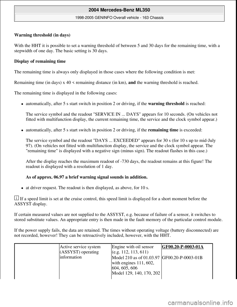
Warning threshold (in days)
With the HHT it is possible to set a warning threshold of between 5 and 30 days for the remaining time, with a
stepwidth of one day. The basic setting is 30 days.
Display of remaining time
The remaining time is always only displayed in those cases where the following condition is met:
Remaining time (in days) x 40 < remaining distance (in km), and the warning threshold is reached.
The remaining time is displayed in the following cases:
automatically, after 5 s start switch in position 2 or driving, if the warning threshold is reached:
The service symbol and the readout "SERVICE IN ... DAYS" appears for 10 seconds. (On vehicles not
fitted with multifunction display, the current remaining time, the service and the clock symbol appear.)
automatically, after 5 s start switch in position 2 or driving, if the remaining time is exceeded:
The service symbol and the readout "DAYS ... EXCEEDED" appears for 30 s (for 10 s up to mid-July
97). (On vehicles not fitted with multifunction display, the service and the clock symbol appear. The
"remaining time" is displayed with a negative sign (minus sign). The readout flashes in this case.)
After the display reaches the maximum readout of -730 days, the readout remains at this figure! The
readout is displayed with a resolution of 1 day.
As of approx. 06.97 a brief warning signal sounds in addition.
at driver request. The readout is then displayed, as above, for 10 s.
If a speed limit is set at the cruise control, this speed limit is displayed for a short moment before the
ASSYST display.
If certain measured values are not supplied to the ASSYST, e.g. because of failure of a sensor, it switches to
stored substitute values. An appropriate entry is then made in the fault memory of the particular control module.
If the power supply fails, the data are retained. The times without operating voltage (battery disconnected) are
not recorded, however! They can be retroactively included, however, with the HHT.
Active service system
(ASSYST) operating
informationEngine with oil sensor
(e.g. 112, 113, 611)GF00.20-P-0003-01A
Model 210 as of 01.03.97
with engines 111, 602,
604, 605, 606
Model 129, 140, 170, 202 GF00.20-P-0003-01B
2004 Mercedes-Benz ML350
1998-2005 GENINFO Overall vehicle - 163 Chassis
me
Saturday, October 02, 2010 3:47:47 PMPage 208 © 2006 Mitchell Repair Information Company, LLC.
Page 3504 of 4133

7.1
Disconnect electrical connectors at the covers
12)
Only with left/right folding outside mirror,
code 500 and headlamp cleaning system,
code 600.
8
Unscrew screw (4) and disconnect connector
(9)
9
Unscrew screw (8) and remove cruise control
switch (S40)
10
Unscrew screws (5)
11
Pull combination switch (S4) off the retaining
webs (6) and remove
12
Install in the reverse order
13
Perform function check
Copyright DaimlerChrysler AG 09.05.2006 CD-Ausgabe G/10/04 . This WIS print-out will not be recorde
d by Modification services.
Page 2
Page 3842 of 4133
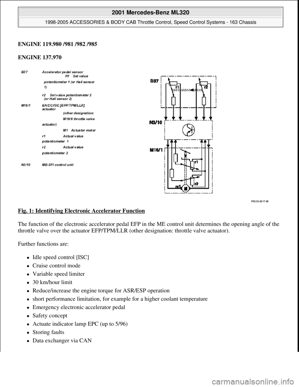
ENGINE 119.980 /981 /982 /985
ENGINE 137.970
Fig. 1: Identifying Electronic Accelerator Function
The function of the electronic accelerator pedal EFP in the ME control unit determines the opening angle of the
throttle valve over the actuator EFP/TPM/LLR (other designation: throttle valve actuator).
Further functions are:
Idle speed control [ISC]
Cruise control mode
Variable speed limiter
30 km/hour limit
Reduce/increase the engine torque for ASR/ESP operation
short performance limitation, for example for a higher coolant temperature
Emergency electronic accelerator pedal
Safety concept
Actuate indicator lamp EPC (up to 5/96)
Storing faults
Data exchanger via CAN
2001 Mercedes-Benz ML320
1998-2005 ACCESSORIES & BODY CAB Throttle Control, Speed Control Systems - 163 Chassis
me
Saturday, October 02, 2010 3:36:27 PMPage 2 © 2006 Mitchell Repair Information Company, LLC.
Page 3843 of 4133
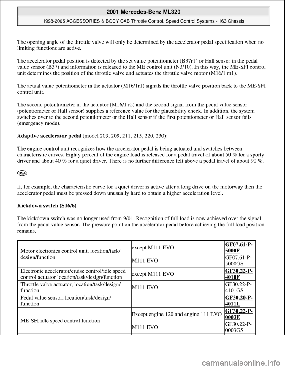
The opening angle of the throttle valve will only be determined by the accelerator pedal specification when no
limiting functions are active.
The accelerator pedal position is detected by the set value potentiometer (B37r1) or Hall sensor in the pedal
value sensor (B37) and information is released to the ME control unit (N3/10). In this way, the ME-SFI control
unit determines the position of the throttle valve and actuates the throttle valve motor (M16/1 m1).
The actual value potentiometer in the actuator (M16/1r1) signals the throttle valve position back to the ME-SFI
control unit.
The second potentiometer in the actuator (M16/1 r2) and the second signal from the pedal value sensor
(potentiometer or Hall sensor) supplies a reference value for the plausibility check. In addition, the system
switches over to the second potentiometer or the Hall sensor if the first potentiometer or Hall sensor fails
(emergency mode).
Adaptive accelerator pedal (model 203, 209, 211, 215, 220, 230):
The engine control unit recognizes how the accelerator pedal is being actuated and switches between
characteristic curves. Eighty percent of the engine load is released for a pedal travel of about 50 % for a sporty
driver and about 40 % for a quiet driver. There is no further difference felt above a pedal travel of about 90 %.
If, for example, the characteristic curve for a quiet driver is active after a long drive on the motorway then the
accelerator pedal must be pressed down unusually hard to obtain a higher acceleration level.
Kickdown switch (S16/6)
The kickdown switch was no longer used from 9/01. Recognition of full load is now achieved over the signal
from the pedal value sensor. The pressure point on the accelerator pedal before achieving the full load position
remains.
Motor electronics control unit, location/task/
design/functionexcept M111 EVOGF07.61-P-
5000F
M111 EVOGF07.61-P-
5000GS
Electronic accelerator/cruise control/idle speed
control actuator location/task/design/functionexcept M111 EVOGF30.22-P-
4010F
Throttle valve actuator, location/task/design/
functionM111 EVOGF30.22-P-
4101GS
Pedal value sensor, location/task/design/
function GF30.20-P-
4011L
ME-SFI idle speed control function
Except engine 120 and engine 111 EVOGF30.22-P-
0003E
M111 EVOGF30.22-P-
0003GS
2001 Mercedes-Benz ML320
1998-2005 ACCESSORIES & BODY CAB Throttle Control, Speed Control Systems - 163 Chassis
me
Saturday, October 02, 2010 3:36:27 PMPage 3 © 2006 Mitchell Repair Information Company, LLC.
Page 3844 of 4133
PEDAL VALUE SENSOR PO SITION - GF30.20-P-4011-01GH
Electronic power control indicator lamp,
location/task/design/functionEngine 119, 120 in Model 129, 140 up to
5/96GF30.20-P-
4012L
Electronic accelerator pe dal emergency running
mode functionEngine 104, 111, 112, 113, 119, 137GF30.20-P-
4026E
30 km/h limit, function
Model 129, 140 with Engine 104,
119.98, 120.98
except GF30.20-P-
4027F
Cruise control (CC) function
With cruise controlGF30.30-P-
0001F
Engine 104 (except HFM sequential
multiport fuel injection/ignition system),
119.98, 120.98
With cruise control
Engine 111, 112, 113, 137GF30.30-P-
0001FA
Variable speed limiter, functionAdditional cruise control function except
GF30.30-P-
3001A
Distronic (DTR), function
Model 220, 215 with code 219a up to
6/00GF30.30-P-
0002K
Model 203, 209, 211, 230 with code
219a
GF30.30-P-
0002KA
Model 215, 220 with code 219a as of
7/00
Pedal value sensor characteristic curve when
reversing function GF30.20-P-
4013E
ASR V control unit location/task/design/function
with code 471 a
Model 129, 140, 202 as of 6/94, 170,
208, 210GF42.40-P-
4500A
ESP control unit location/task/function
with code 472a
Model 129 with Engine 104, 119, 120
Model 140
Model 210 with engine 119
GF42.45-P-
4500A
with code 472a
Model 129 with engine 112, 113
Model 163 up to 8/02, 168, 215
Model 220 (except 220.08/18) Model
202, 208 with engine 112, 113
Model 210 with engine 111, 112, 113
GF42.45-P-
4500B
with code 472a
Model 170 with Engine 111, 112
Model 202, 208 with Engine 111
Model 203
GF42.45-P-
4500C
Model 211, 230GF42.45-P-
4500SL
2001 Mercedes-Benz ML320
1998-2005 ACCESSORIES & BODY CAB Throttle Control, Speed Control Systems - 163 Chassis
me
Saturday, October 02, 2010 3:36:27 PMPage 4 © 2006 Mitchell Repair Information Company, LLC.
Page 3852 of 4133
ENGINE 119.980 /981 /982 /985
ENGINE 120.982/983
ENGINE 137.970
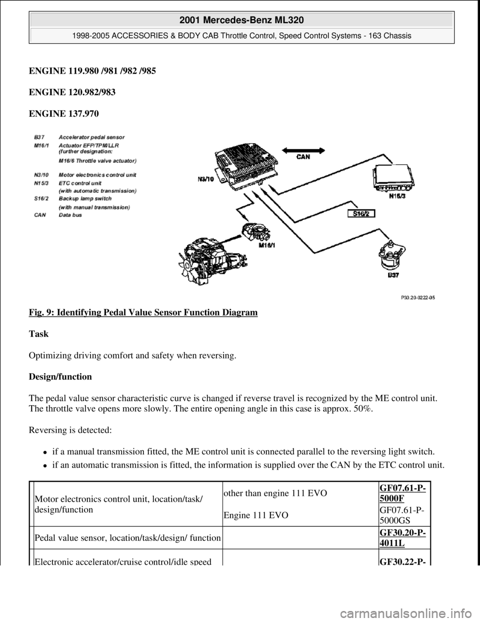
Fig. 9: Identifying Pedal Value Sensor Function Diagram
Task
Optimizing driving comfort and safety when reversing.
Design/function
The pedal value sensor characteristic curve is changed if reverse travel is recognized by the ME control unit.
The throttle valve opens more slowly. The entire opening angle in this case is approx. 50%.
Reversing is detected:
if a manual transmission fitted, the ME control unit is connected parallel to the reversing light switch.
if an automatic transmission is fitted, the information is supplied over the CAN by the ETC control unit.
Motor electronics control unit, location/task/
design/functionother than engine 111 EVOGF07.61-P-
5000F
Engine 111 EVOGF07.61-P-
5000GS
Pedal value sensor, location/task/design/ function GF30.20-P-
4011L
Electronic accelerator/cruise control/idle speed GF30.22-P-
2001 Mercedes-Benz ML320
1998-2005 ACCESSORIES & BODY CAB Throttle Control, Speed Control Systems - 163 Chassis
me
Saturday, October 02, 2010 3:36:27 PMPage 12 © 2006 Mitchell Repair Information Company, LLC.