1997 MERCEDES-BENZ ML430 fuel
[x] Cancel search: fuelPage 3783 of 4133

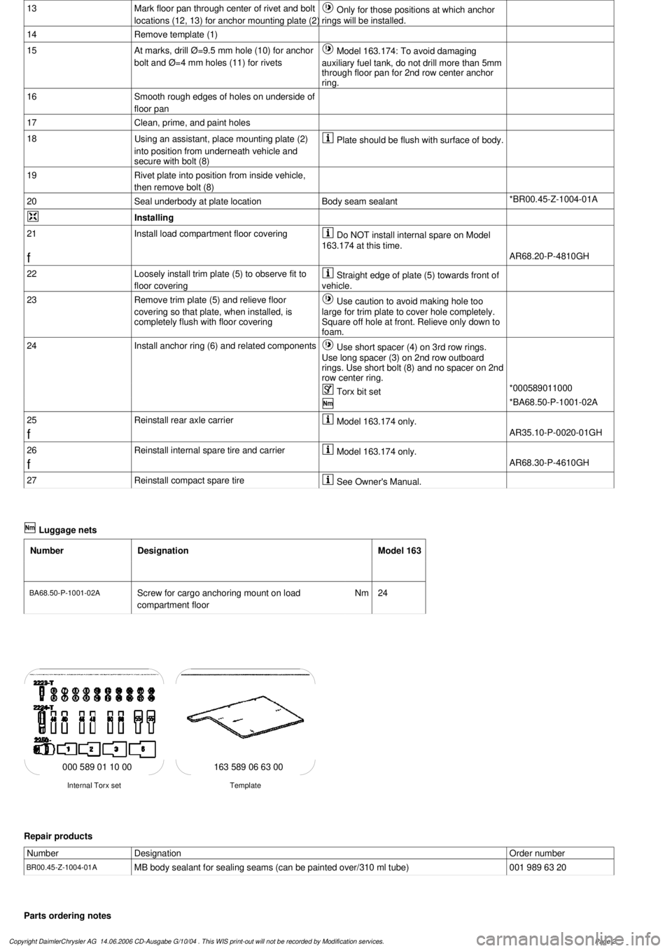
13
Mark floor pan through center of rivet and bolt
locations (12, 13) for anchor mounting plate (2)
Only for those positions at which anchor
rings will be installed.
14
Remove template (1)
15
At marks, drill Ø=9.5 mm hole (10) for anchor
bolt and Ø=4 mm holes (11) for rivets
Model 163.174: To avoid damaging
auxiliary fuel tank, do not drill more than 5mm
through floor pan for 2nd row center anchor
ring.
16
Smooth rough edges of holes on underside of
floor pan
17
Clean, prime, and paint holes
18
Using an assistant, place mounting plate (2)
into position from underneath vehicle and
secure with bolt (8)
Plate should be flush with surface of body.
19
Rivet plate into position from inside vehicle,
then remove bolt (8)
20
Seal underbody at plate location
Body seam sealant
*BR00.45-Z-1004-01A
Installing
21
Install load compartment floor covering
Do NOT install internal spare on Model
163.174 at this time.
f
AR68.20-P-4810GH
22
Loosely install trim plate (5) to observe fit to
floor covering
Straight edge of plate (5) towards front of
vehicle.
23
Remove trim plate (5) and relieve floor
covering so that plate, when installed, is
completely flush with floor covering
Use caution to avoid making hole too
large for trim plate to cover hole completely.
Square off hole at front. Relieve only down to
foam.
24
Install anchor ring (6) and related components
Use short spacer (4) on 3rd row rings.
Use long spacer (3) on 2nd row outboard
rings. Use short bolt (8) and no spacer on 2nd
row center ring.
Torx bit set
*000589011000
*BA68.50-P-1001-02A
25
Reinstall rear axle carrier
Model 163.174 only.
f
AR35.10-P-0020-01GH
26
Reinstall internal spare tire and carrier
Model 163.174 only.
f
AR68.30-P-4610GH
27
Reinstall compact spare tire
See Owner's Manual.
Luggage nets
Number
Designation
Model 163
BA68.50-P-1001-02A
Screw for cargo anchoring mount on load
compartment floor
Nm
24
163 589 06 63 00
Template
Internal Torx set
000 589 01 10 00
Repair products
Number
Designation
Order number
BR00.45-Z-1004-01A
MB body sealant for sealing seams (can be painted over/310 ml tube)
001 989 63 20
Parts ordering notes
Copyright DaimlerChrysler AG 14.06.2006 CD-Ausgabe G/10/04 . This WIS print-out will not be recorde
d by Modification services.
Page 2
Page 3831 of 4133

SI47.10-P-0007A
Service Information: Procedure for fuel tank leaks
14.8.03
MODEL
124, 126, 129, 140, 163, 168, 170, 201, 202, 203, 208, 209, 210, 211, 215, 220, 230, 240, 460, 461, 463
If a fuel tank has a leak which was caused by an accident with
another vehicle, bottoming out, etc., this
cannot
be claimed as a
warranty/goodwill case.
We
explicitly
state here that repair measures
(e.g. welding, bonding, etc.) on fuel tanks made out of sheet metal or
plastic are not permissible.
The fuel tank is always to be replaced when leaks are determined
which have been caused by damage to the upper or lower sides of
the fuel tank.
Copyright DaimlerChrysler AG 28.05.2006 CD-Ausgabe G/10/04 . This WIS print-out will not be recorde
d by Modification services.
Page 1
Page 3832 of 4133

SI47.10-P-0004A
Service Information: Procedure when tank is filled with incorrect fuel
19.12.00
MODEL
202 with ENGINE 611
MODEL
203 with ENGINE 611, 612, 646
MODEL
210 with ENGINE 611, 612, 613
MODEL
220 with ENGINE 613, 628, 648
MODEL
163 with ENGINE 612, 628
MODEL
168 with ENGINE 668
MODEL
209 with ENGINE 612
MODEL
211 with ENGINE 628, 646, 647, 648
MODEL
463 with ENGINE 612, 628
Modification notes
26.7.04
Engines have been added and procedure has been updated
Incorrect refueling of diesel-power vehicles with a common rail
injection system. Please be aware that if the customer fills the fuel
tank with the wrong type of fuel, this is the customer's fault and
cannot be submitted as a warranty claim.
If the diesel-powered vehicle with a common rail injection system has
been refueled with gasoline, follow the steps below:
1.
If the engine was not started after fuel tank is filled with the wrong
type of fuel, then emptying the fuel tank and cleaning the fuel low-
pressure lines should be enough to solve the problem.
2.
If the engine was started after fuel tank was filled with wrong type
of fuel:
On engines 611, 612, 613, 668:
-
On the rail, open the low pressure connection of the high
pressure pump return (plastic connection in area of pressure
regulator valve) and check connecting point in rail for chips.
On engine 646, 647, 648, 628:
-
Disconnect Y-distributor unit (return line HDP/Rail) at the output
and, with ignition ON, collect the fuel in a clean container. Check
fuel for metal shavings.
If the high pressure pump is not damaged and there are no metal
shavings in the injection system:
-
As in step 1, empty fuel as per the guidelines and clean the fuel
low-pressure lines. In addition to this, remove/install/replace the
high-pressure pump and fuel filter.
If metal shavings are found in the fuel
system or the high pressure pump drive is
damaged:
#
b
Engine runs rough, surges or does not start
ENGINE 611 in MODEL 203, 202, 210
ENGINE 612 in MODEL 163, 203, 210, 209
ENGINE 613 in MODEL 210, 220
ENGINE 628 in MODEL 163, 220, 211
ENGINE 646 in MODEL 203, 211
ENGINE 647 in MODEL 211
ENGINE 648 in MODEL 220, 211
ENGINE 668 in MODEL 168
ENGINE 612, 628 in MODEL 463
AF07.00-P-9000B
Copyright DaimlerChrysler AG 28.05.2006 CD-Ausgabe G/10/04 . This WIS print-out will not be recorde
d by Modification services.
Page 1
Page 3835 of 4133

SI18.00-P-0010A
Service Information: oil sludge
26.3.01
ENGINE
111 in MODELS 124, 163, 170, 202, 203, 208, 210
ENGINE
112 in MODELS 129, 163, 170, 202, 203, 208, 210, 220
ENGINE
112, 113 in MODEL 463
ENGINE
113 in MODELS 129, 163, 202, 208, 210, 215, 220
ENGINE
137 in MODEL 215, 220
ENGINE
166 in MODEL 168
Oil sludging in gasoline engines with ASSYST maintenance
system
Recently we have determined that time and time again oil
sludging occurs in gasoline engines with an ASSYST maintenance
system.
Oil sludging can lead to the following complaints:
D
engine oil consumption
D
engine smoke (white/blue)
D
influencing of oil level indicator
D
clogged oil filter, engine oil thickened like jelly
D
Check engine lamp illuminated
D
oil sludge visible during assembly job, e.g. in oil filter, in cylinder
head covers, condensation sludging
(engine 166) etc.
-----------------------------------------------------------------------------------------
The following list of causes may lead individually or as a combination
to engine oil sludging:
D
Crankcase ventilation inoperable, function orifices, bores,
passages in cylinder head cover, cylinder head, crankcase etc.
are mechanically sealed. A nonfunctioning crankcase
ventilation boosts loads on the engine oil through organic
nitrates. The risk of oil sludging increases.
The mechanical condition of the engine is always to be
checked, i.e. all engine oil drain orifices on the cylinder head
and crankcase and all crankcase ventilation ducts must be free
of obstacles. Crankcase breather lines may not be kinked.
Check the ventilation bores in the cylinder head covers.
-----------------------------------------------------------------------------------------
D
The engine oil used does not comply with the specifications in
Sheet 229.1 or 229.3 of the Specifications for Service Products.
The additive process, e.g. dirt-carrying capability, neutralization
capability and oxidation resistance as well as the quality of the
base stock influence sludging time.
Use of engine oils with best possible resistance to formation of
sludge, i.e. use only tested and approved engine oils (from
Sheet 229.1 or 229.3). The best protection is afforded by the
engine oils on Sheet 229.3, which fulfill more stringent
specifications with regard to preventing sludge and deposits
(see Sheet 221.0, page 11). These oils have a distinctly better
anti-sludge characteristic than other engine oils.
D
Sludging after adding a fuel or engine oil special additive.
Do not use fuel or engine oil special additives. More information
hereto is available on Sheet 219.0 of the Specifications for
Service products. Reference to customer not to use special
additives.
D
Engine oil change not performed according to ASSYST
specifications. At driven distances
exceeding > approx. 3000 km, engine oil sludging may occur.
-----------------------------------------------------------------------------------------
Comply with engine oil and filter change as under ASSYST
specifications. Observe remaining distance.
D
Fuel grade lies outside standard (regionally contingent). If
contaminated, deficient fuel is used, then engine oil sludging
may occur even where approved engine oil is used.
Operation with fuel, e.g. as under DIN EN 228. Clarify refueling
behavior of customer. If engine operation regional, is
temporarily possible with deficient oil only, then the startup
distance has to be individually reduced, i.e. the oil change
temporarily performed at an interval of, e.g. 10,000 km.
D
Radiator antifreeze penetration into engine oil, e.g. through an
internal engine leak (cylinder head gasket, casting porosity).
The engine oil sludges within a short period. The crankcase
ventilation clogs up and stops functioning. Condensation
sludging clogs up the oil separator cells
(engine 166).
Rectify coolant leakage. Clean all sludged engine parts, in
particular the crankcase ventilation parts. If the occurrence
repeats, and casting porosity is suspected, e.g. replace
crankcase.
-----------------------------------------------------------------------------------------
Copyright DaimlerChrysler AG 20.05.2006 CD-Ausgabe G/10/04 . This WIS print-out will not be recorde
d by Modification services.
Page 1
Page 3836 of 4133

Measures for slightly sludged engine:
Oil and filter change. Purge engine, i.e. normal engine operation
in neutral, or while driving, using oil from Sheet 229.3, 228.3, or
228.5. Drain off scavenging oil after purging process (approx. 1
hour). Repeat purging process if necessary. Refill using engine oil
from Sheet 229.3, or 229.1. The first oil change after clearing the
sludge should be performed after approx. 10,000 km or beforehand;
when doing so use engine oil from Sheet 229.3.
Measures for severely sludged engine:
Engines with severe oil sludging and caking onto engine parts
and into bores have to be dismantled and mechanically cleaned.
Tough sludge residue must not enter the clean side of the oil circuit,
as otherwise, e.g. the piston oil spray and the hydraulic
compensation elements may have their functionality impaired. Refill
using engine oil from Sheet 229.3, or 229.1.
The first oil change after sludging should be performed after approx.
10,000 km; when doing so use engine oil from
Sheet 229.3.
Warranty/goodwill regulations
If in combination with engine oil sludging a warranty/goodwill claim is
submitted, then a regular documentation of maintenance must be
presented. The ASSYST printout is to be filed carefully for further
reference.
Oil sludging in combination with an exceeded oil change interval, or
because of special additives in the fuel/engine oil are costs to be
borne by the customer.
Copyright DaimlerChrysler AG 20.05.2006 CD-Ausgabe G/10/04 . This WIS print-out will not be recorde
d by Modification services.
Page 2
Page 3844 of 4133

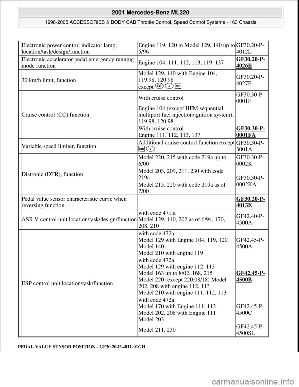
PEDAL VALUE SENSOR PO SITION - GF30.20-P-4011-01GH
Electronic power control indicator lamp,
location/task/design/functionEngine 119, 120 in Model 129, 140 up to
5/96GF30.20-P-
4012L
Electronic accelerator pe dal emergency running
mode functionEngine 104, 111, 112, 113, 119, 137GF30.20-P-
4026E
30 km/h limit, function
Model 129, 140 with Engine 104,
119.98, 120.98
except GF30.20-P-
4027F
Cruise control (CC) function
With cruise controlGF30.30-P-
0001F
Engine 104 (except HFM sequential
multiport fuel injection/ignition system),
119.98, 120.98
With cruise control
Engine 111, 112, 113, 137GF30.30-P-
0001FA
Variable speed limiter, functionAdditional cruise control function except
GF30.30-P-
3001A
Distronic (DTR), function
Model 220, 215 with code 219a up to
6/00GF30.30-P-
0002K
Model 203, 209, 211, 230 with code
219a
GF30.30-P-
0002KA
Model 215, 220 with code 219a as of
7/00
Pedal value sensor characteristic curve when
reversing function GF30.20-P-
4013E
ASR V control unit location/task/design/function
with code 471 a
Model 129, 140, 202 as of 6/94, 170,
208, 210GF42.40-P-
4500A
ESP control unit location/task/function
with code 472a
Model 129 with Engine 104, 119, 120
Model 140
Model 210 with engine 119
GF42.45-P-
4500A
with code 472a
Model 129 with engine 112, 113
Model 163 up to 8/02, 168, 215
Model 220 (except 220.08/18) Model
202, 208 with engine 112, 113
Model 210 with engine 111, 112, 113
GF42.45-P-
4500B
with code 472a
Model 170 with Engine 111, 112
Model 202, 208 with Engine 111
Model 203
GF42.45-P-
4500C
Model 211, 230GF42.45-P-
4500SL
2001 Mercedes-Benz ML320
1998-2005 ACCESSORIES & BODY CAB Throttle Control, Speed Control Systems - 163 Chassis
me
Saturday, October 02, 2010 3:36:27 PMPage 4 © 2006 Mitchell Repair Information Company, LLC.
Page 3854 of 4133

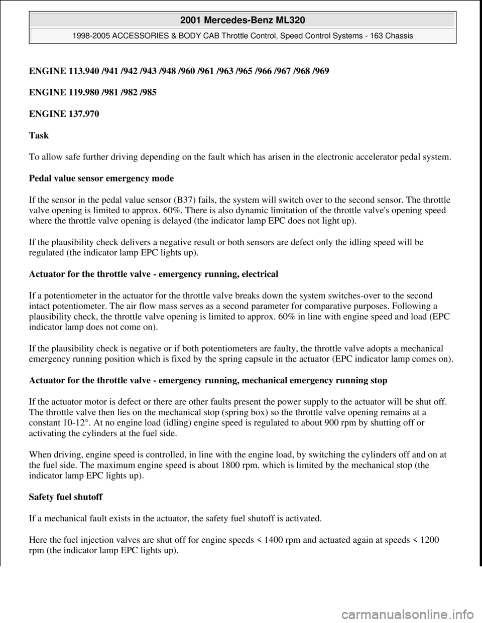
ENGINE 113.940 /941 /942 /943 /948 /960 /961 /963 /965 /966 /967 /968 /969
ENGINE 119.980 /981 /982 /985
ENGINE 137.970
Task
To allow safe further driving depending on the fault which has arisen in the electronic accelerator pedal system.
Pedal value sensor emergency mode
If the sensor in the pedal value sensor (B37) fails, the system will switch over to the second sensor. The throttle
valve opening is limited to approx. 60%. There is also dynamic limitation of the throttle valve's opening speed
where the throttle valve opening is delayed (the indicator lamp EPC does not light up).
If the plausibility check delivers a negative result or both sensors are defect only the idling speed will be
regulated (the indicator lamp EPC lights up).
Actuator for the throttle valve - emergency running, electrical
If a potentiometer in the actuator for the throttle valve breaks down the system switches-over to the second
intact potentiometer. The air flow mass serves as a second parameter for comparative purposes. Following a
plausibility check, the throttle valve opening is limited to approx. 60% in line with engine speed and load (EPC
indicator lamp does not come on).
If the plausibility check is negative or if both potentiometers are faulty, the throttle valve adopts a mechanical
emergency running position which is fixed by the spring capsule in the actuator (EPC indicator lamp comes on).
Actuator for the throttle valve - emergency running, mechanical emergency running stop
If the actuator motor is defect or there are other faults present the power supply to the actuator will be shut off.
The throttle valve then lies on the mechanical stop (spring box) so the throttle valve opening remains at a
constant 10-12°. At no engine load (idling) engine speed is regulated to about 900 rpm by shutting off or
activating the cylinders at the fuel side.
When driving, engine speed is controlled, in line with the engine load, by switching the cylinders off and on at
the fuel side. The maximum engine speed is about 1800 rpm. which is limited by the mechanical stop (the
indicator lamp EPC lights up).
Safety fuel shutoff
If a mechanical fault exists in the actuator, the safety fuel shutoff is activated.
Here the fuel injection valves are shut off for engine speeds < 1400 rpm and actuated again at speeds < 1200
rpm (the indicator lamp EPC li
ghts up).
2001 Mercedes-Benz ML320
1998-2005 ACCESSORIES & BODY CAB Throttle Control, Speed Control Systems - 163 Chassis
me
Saturday, October 02, 2010 3:36:27 PMPage 14 © 2006 Mitchell Repair Information Company, LLC.
Page 3858 of 4133

vehicles delivered from 6/00 is increased for the driving mode selected by about 100 rpm when the switch-on
threshold of about 900 rpm is exceeded. This increase is cancelled again when the external temperature drops
below 32° C.
Undervoltage
If the engine control unit detects an undervoltage the idling speed is increased until the ignition is switched off
for the driving mode selected by about 100 rpm.
If the control unit SBC reports an undervoltage to the engine control unit over CAN the idling speed for the
driving mode selected is increased to about 750 rpm.
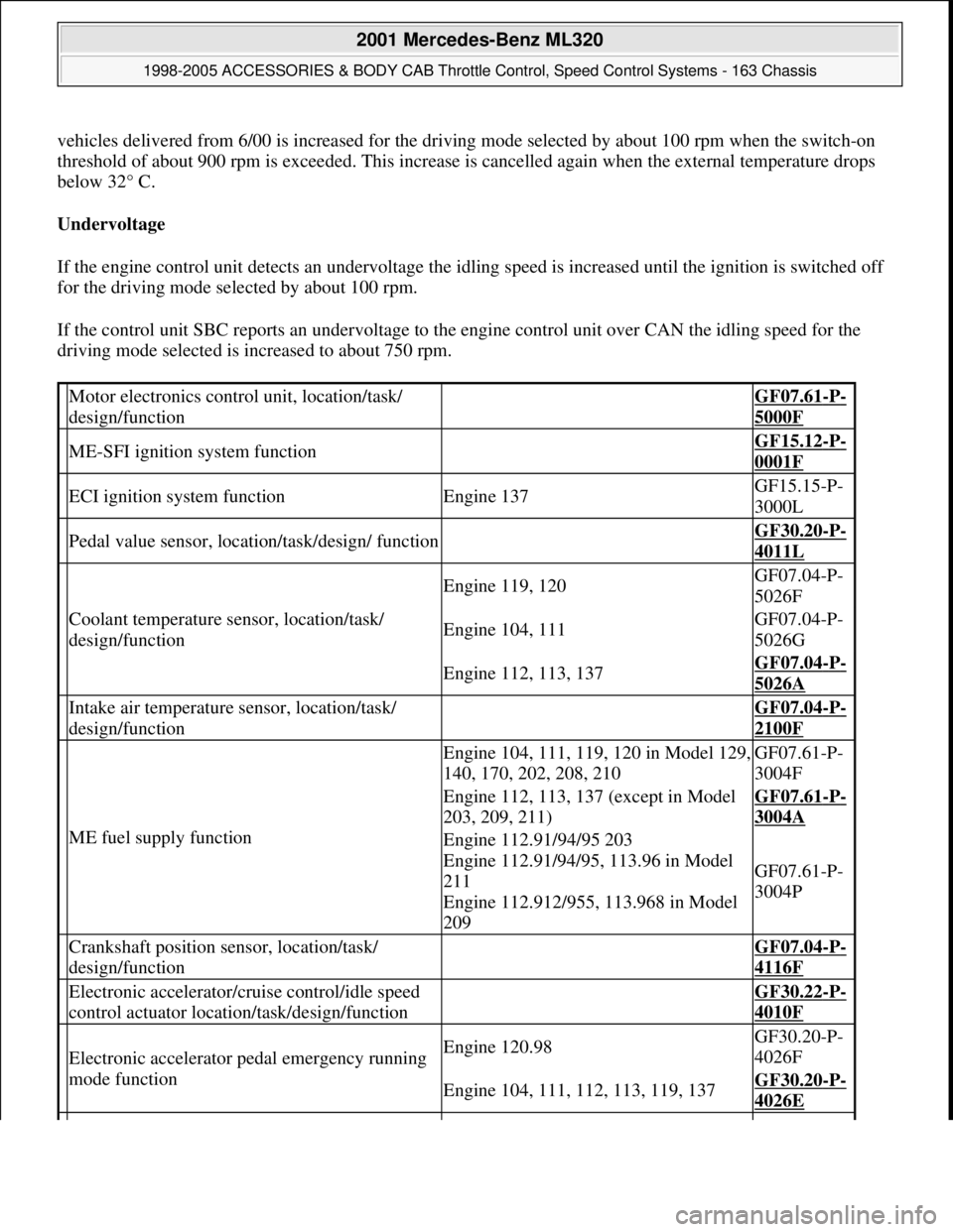
Motor electronics control unit, location/task/
design/function GF07.61-P-
5000F
ME-SFI ignition system function GF15.12-P-
0001F
ECI ignition system functionEngine 137GF15.15-P-
3000L
Pedal value sensor, location/task/design/ function GF30.20-P-
4011L
Coolant temperature sensor, location/task/
design/function
Engine 119, 120GF07.04-P-
5026F
Engine 104, 111GF07.04-P-
5026G
Engine 112, 113, 137GF07.04-P-
5026A
Intake air temperature sensor, location/task/
design/function GF07.04-P-
2100F
ME fuel supply function
Engine 104, 111, 119, 120 in Model 129,
140, 170, 202, 208, 210GF07.61-P-
3004F
Engine 112, 113, 137 (except in Model
203, 209, 211)GF07.61-P-
3004A
Engine 112.91/94/95 203
Engine 112.91/94/95, 113.96 in Model
211
Engine 112.912/955, 113.968 in Model
209
GF07.61-P-
3004P
Crankshaft position sensor, location/task/
design/function GF07.04-P-
4116F
Electronic accelerator/cruise control/idle speed
control actuator location/task/design/function GF30.22-P-
4010F
Electronic accelerator pedal emergency running
mode functionEngine 120.98GF30.20-P-
4026F
Engine 104, 111, 112, 113, 119, 137GF30.20-P-
4026E
2001 Mercedes-Benz ML320
1998-2005 ACCESSORIES & BODY CAB Throttle Control, Speed Control Systems - 163 Chassis
me
Saturday, October 02, 2010 3:36:27 PMPage 18 © 2006 Mitchell Repair Information Company, LLC.