1997 MERCEDES-BENZ ML430 manual radio set
[x] Cancel search: manual radio setPage 1633 of 4133
Multifunction keys "NUM " and "NAME ".
Entering code
The telephone can be protected against undesired use by entering a three - digit code. All telephone
functions are disabled except the emergency call function.
The telephone can be enabled again by entering the three - digit code (correction possible with " Clear" button
in the event of incorrect entry) and actuation of the multifunction key" OK ".
The following functions are available in the telephone mode:
Emergency call function
This function offers the possibility of transmitting an emergency call within the reception range of the
radio telephone network. The emergency call number is stored in the memory location 1 and can be
called even when the telephone is disabled. The emergency call is performed by pressing and holding
control button 1 down longer than 1 second " EMERGENCY " appears on the display. An emergency
call can be terminated by pressing " the "END " button.
Manual entry of telephone number
Telephone numbers can be entered manually on the number pad.
An incorrectly entered number can be deleted by momentarily pressing the " CLEAR " button. If the" CLEAR
" button is pressed for longer than 2 s all telephone numbers deleted
If the number entered consists of only 1 or 2 numbers, the telephone number stored in the memory with this
code is dialed.
The entered telephone number can be transmitted to the telephone by pressing the " SEND " button. The
telephone compares the transmitted telephone number with the telephone number stored in the memory. If the
numbers coincide the associated name, the memory location number and the telephone appear on the display
(depending on setting).
If the numbers do not coincide, the telephone number entered is still displayed.
Then the connection can be completed. The duration of the telephone call is indicated in minutes and seconds.
The call can be terminated by pressing the " END " button.
Selecting stored telephone number
The memory can be called up by pressing the multifunction key" NAME " or "NUM "."NAME "
indicates the stored names on the display" NUM " indicates the memory location number as well as the
associated telephone number. By pressing the" joystick " up or down the stored entries are displayed.
Pressin
g to the right or left causes display of the next 4entries or previous 4 entries.
2001 Mercedes-Benz ML320
1998-2005 ACCESSORIES & BODY, CAB Electrical System - Body - 163 Chassis
me
Saturday, October 02, 2010 3:30:06 PMPage 138 © 2006 Mitchell Repair Information Company, LLC.
Page 1634 of 4133
If a name is not available for the stored telephone number, the display is switched over and the
memory location and the telephone number are displayed.
By manually entering 1 or 2 numbers and subsequent actuation of the multifunction key" NAME " or
"NUM " the name stored under this memory location number or the stored telephone number are
indicated.
Pressing " SEND " button completes the desired connection. If no connection is to be completed, the
memory area can be exited by pressing the multifunction key" EXIT ".
Quick dial
When a one or two-digit number is entered and the " SEND " button is actuated the telephone number
stored under this memory location number is dialed.
By pressing and holding one of the number buttons 1 to 9 for more than 2 s the telephone number stored
under this memory location number is dialed. In this case it is not necessary to actuate the " SEND "
button.
Memory location functions 1 number is reserved for emergency !
Redialing
Pressing the" SEND " button without previously entering a telephone number calls up the last 5 selected
telephone numbers on the display. It is possible to select the desired telephone number by pressing the"
joystick " up or down. The connection is completed by actuating the" SEND " button. This area can be
exited by pressing the multifunction key" EXIT ".
Incoming calls
During an incoming call all other audio sources are set to mute and "CALL " appears on the display. The
call can be accepted by pressing the " SEND " button or terminated by pressing the" END " button.
During a call it is possible to continue dialing, e.g. enter a code number for an answering machine.
CASSETTE MODE, FUNCTION - GF82.85-P-2010GI
MODEL 163 as of 1.9.01 with CODE (522) Modular control system (MCS) radio USA with CODE (357)
Navigation system - additional unit with CODE (818b) Single CD player - additional unit with CODE
(491) U.S. version
GPS roof
antenna/telephone,
location/purpose/
design/function GF82.70-P-
4111A
2001 Mercedes-Benz ML320
1998-2005 ACCESSORIES & BODY, CAB Electrical System - Body - 163 Chassis
me
Saturday, October 02, 2010 3:30:06 PMPage 139 © 2006 Mitchell Repair Information Company, LLC.
Page 1700 of 4133
RADIO (RD) DIAGNOSIS, FUNCTION CHECK - AD82.60-P-3000A
MODEL 124, 129, 140, 163, 168, 170, 202, 208, 210 with MB radio
MODEL 129, 140, 168, 170, 202, 208, 210 with MB radio and navigation operating unit, APS
RADIO (RD) DIAGNOSIS, TROUBLESHOOTING - AD82.60-P-5000A
MODEL 124, 129, 140, 163, 168, 170, 202, 208, 210 with MB radio
MODEL 129, 140, 168, 170, 202, 208, 210 with MB radio and navigation operating unit, APS
Function notes, radio
(RD)Model 129AD82.60-P-2000-04A
Radio (RD) diagnosis, advanced
information AD82.60-P-2000A
Battery voltage 11-14 V
Fuses okay
Function check
Scope of test Operation/Requirement Specified value Possible cause/
Remedy
1
Radio functions in
accordance with
Owner's ManualRadio: ON
Set station with good reception
(music) or play music cassette or
CD.
Fader, bass, treble and balance in
position 0 (readout in display).
Perform all control functionsRadio reception,
cassettes/CD
operation, loudness,
sound and readouts in
display must be
faultless
Local and
atmospheric
influences must be
taken into account
with radio reception.
They may cause
interference and poor
radio reception.AD82.60-P-5000A
Models 129, 170,202,
208, 210 as of 06/98
with digital data bus
(D2B): ?
AD82.60-P-4000A
Radio (RD) diagnosis,
previous knowledge AD82.60-P-2000A
Troubleshooting
Complaint Possible cause Note Remedy
Radio completely
inoperativeVoltage supply for radio
(A2) or APS radio and AD82.60-P-6000-01A
2001 Mercedes-Benz ML320
1998-2005 ACCESSORIES & BODY, CAB Electrical System - Body - 163 Chassis
me
Saturday, October 02, 2010 3:30:07 PMPage 205 © 2006 Mitchell Repair Information Company, LLC.
Page 3228 of 4133
A/C housing. Disconnect control module connector. To install reverse removal procedure. Recode 5-digit radio
security code. Using HHT, check for DTC and erase, and set clock.
A/C PUSH BUTTON CONTROL PANEL
Removal & Installation
1. Obtain 5-digit radio security code from vehicle owner. Disconnect negative battery cable. Using radio
removal plates, remove radio. Disconnect electrical connectors.
2. Remove instrument panel center section. Remove 4 A/C control panel screws and remove control panel.
Release pull cables and disconnect connectors. To install, reverse removal procedure. Recode radio. See
RECODING RADIO
under PROGRAMMING.
BLOWER MOTOR
Removal & Installation
Remove passenger-side instrument panel under cover. Remove blower motor mounting screws from A/C
housing unit. Disconnect blower motor connector and remove blower motor. To install, reverse removal
procedure.
COMPRESSOR
Removal & Installation
1. Discharge A/C system, using approved refrigerant recovery/recycling equipment. Remove accessory
drive belt. Disconnect low pressure refrigerant line from compressor. Discard "O" rings. Plug exposed
openings to protect A/C system from debris and moisture.
2. Disconnect high pressure refrigerant line from compressor. Discard "O" rings. Plug exposed openings to
protect A/C system from debris and moisture. Disconnect electrical connector. Remove compressor
mounting bolts.
3. Raise and support vehicle. Remove compressor from under vehicle without spilling refrigerant oil. To
install, reverse removal procedure. Ensure refrigerant oil quantity in compressor is correct. See
COMPRESSOR REFRIGERANT OIL CHECKING under GENERAL SERVICING. Tighten bolts to
specification. See TORQUE SPECIFICATIONS
.
CONDENSER
Removal & Installation
1. Discharge A/C system, using approved refrigerant recovery/recycling equipment. Remove cooling fans.
See COOLING FANS
. Disconnect refrigerant line from receiver-drier. See Fig. 5 . Discard "O" rings.
2. Plug exposed openings to protect A/C system from debris and moisture. Remove refrigerant line from
condenser. Remove radiator upper rubber seal. See Fig. 6
. Remove condenser upper mounting screws.
Lift condenser upward and remove. NOTE: Each time A/C compressor is removed and installed, receiver-drier must be
replaced.
2001 Mercedes-Benz ML320
2000-01 MANUAL A/C-HEATER SYSTEMS ML 320, ML 430 & ML 55
me
Saturday, October 02, 2010 3:25:10 PMPage 17 © 2006 Mitchell Repair Information Company, LLC.
Page 3232 of 4133
Fig. 6: Removing Cooling Fans & Condenser
Courtesy of MERCEDES-BENZ OF NORTH AMERICA.
COOLING FANS
Removal & Installation
Remove headlight units. Remove upper frame crossmember, release hood release control cable and remove
crossmember. See Fig. 6
. Remove 2 cooling fans frame bolts on radiator. Disconnect cooling fan connector.
Release outside temperature sensor wiring harness. Pull up on cooling fan and remove. To install, reverse
removal procedure. Ensure cooling fan bottom guides are properly seated in lower mounts.
EVAPORATOR
Removal & Installation
Remove A/C housing unit. See A/C HOUSING UNIT . Remove expansion valve. See Fig. 5 . Discard "O"
rings. Disassemble A/C housing unit. Remove evaporator. Remove evaporator temperature sensor. To install,
reverse removal procedure. Use NEW "O" rings lubricated with refrigerant oil. If installing a new or repair
evaporator, add 1.35 ounces of NEW refrigerant oil to evaporator.
EXPANSION VALVE
Removal & Installation
1. Discharge A/C system, using approved refrigerant recovery/recycling equipment. Without disconnecting
coolant hoses, remove coolant expansion reservoir and set aside. Remove refrigerant line bracket and
loosen clamps. See Fig. 5
. Pull refrigerant lines out of expansion valve.
2. Remove expansion valve self-locking nut and discard. Remove expansion valve. Discard "O" rings. To
install, reverse removal procedure. Use NEW "O" rings lubricated with refrigerant oil. Tighten NEW self-
locking nut to specification. See TORQUE SPECIFICATIONS
.
INSTRUMENT PANEL & INSTRUMENT PANEL CARRIER
Removal & Installation
1. Secure vehicle against rolling. Set transmission selector to "D" position. Obtain radio security code.
Disconnect negative battery cable. Remove driver-side air bag.
2. Place match marks on steering wheel and steering shaft. Remove steering wheel, upper steering column
covers and combination switch. Remove instrument cluster cover frame. Remove one instrument panel
lower section bolt.
3. Remove screws in footwell from left side of instrument panel bottom section. Remove instrument panel
center section. Remove 4 A/C control panel screws and remove control panel. See Fig. 1
. Release pull
cables and disconnect connectors.
4. Remove screws from center section. Remove glove box. Remove screws in footwell from right side of
instrument panel bottom section. Remove entry courtesy lights. Remove end covers and screws.
5. Release 4 "A" clips between instrument panel bottom section and upper section. See Fig. 7
. Release
parkin
g brake release cable from handle. With assistance, remove instrument panel bottom section.
2001 Mercedes-Benz ML320
2000-01 MANUAL A/C-HEATER SYSTEMS ML 320, ML 430 & ML 55
me
Saturday, October 02, 2010 3:25:10 PMPage 21 © 2006 Mitchell Repair Information Company, LLC.
Page 3885 of 4133
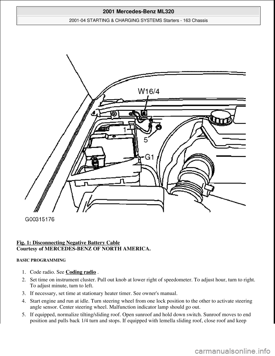
Fig. 1: Disconnecting Negative Battery Cable
Courtesy of MERCEDES-BENZ OF NORTH AMERICA.
BASIC PROGRAMMING
1. Code radio. See Coding radio .
2. Set time on instrument cluster. Pull out knob at lowe r right of speedometer. To adjust hour, turn to right.
To adjust minute, turn to left.
3. If necessary, set time at stationary heater timer. See owner's manual.
4. Start engine and run at idle. Turn steering wheel fr om one lock position to the other to activate steering
angle sensor. Center steering wheel. Ma lfunction indicator lamp should go out.
5. If equipped, normalize ti lting/sliding roof. Open sunroof and hold down switch. Sunroof moves to end
position and pulls back 1/4 turn and stops. If equipped with lemella slidin
g roof, close roof and keep
2001 Mercedes-Benz ML320
2001-04 STARTING & CHARGING SYSTEMS Starters - 163 Chassis
me
Saturday, October 02, 2010 3:19:47 PMPage 3 © 2006 Mitchell Repair Information Company, LLC.