Page 864 of 4133

60 Safety and SecurityOccupant safety�
Adjust the passenger seat as far as pos-
sible rearward from the dashboard when
the seat is occupied.
�
Occupants, especially children, should
never lean their heads in the area of the
door where the side impact airbag in-
flates. This could result in serious inju-
ries or death should the airbag be
triggered. Always sit upright, properly
use the seat belts and appropriate size
infant or child restraint system.
�
Children 12 years old and under must
never ride in the front seat, except in a
Mercedes-Benz authorized
BabySmart
TM1
compatible child seat,
which operates with the BabySmart
TM
system installed in the vehicle to deacti-
vate the passenger front airbag when it
is properly installed. Otherwise they will
be struck by the airbag when it inflates
in a crash. If this happens, serious or fa-
tal injury will result.
1BabySmart
TMis a trademark of Siemens
Automotive Corp.
Failure to follow these instructions can re-
sult in severe injuries to you or other occu-
pants.
If you sell your vehicle you are responsible
to make the buyer aware of these points. Be
sure to give the buyer this Operator’s
Manual.
Warning
G
Accident research shows that the safest
place for children in an automobile is in the
rear seat. Should you choose to place a child
12 years old or under in the front passenger
seat of your vehicle, you must properly use
a BabySmart
TM child restraint which will
turn off the passenger front airbag
(
�page 70). BabySmart
TM will not, howev-
er, turn off any side impact airbag.
It should be noted that with respect to both
front and rear side impact airbags there is a
possibility for a side airbag related injury if
occupants, especially children, are not prop-
erly seated or restrained when next to a side
airbag which needs to deploy rapidly in a
side impact in order to do its job.
��
Page 935 of 4133
131 Controls in detail
Good visibility
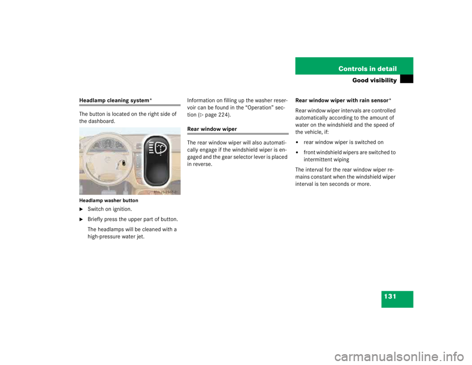
Headlamp cleaning system*
The button is located on the right side of
the dashboard.Headlamp washer button�
Switch on ignition.
�
Briefly press the upper part of button.
The headlamps will be cleaned with a
high-pressure water jet.Information on filling up the washer reser-
voir can be found in the “Operation” sec-
tion (
�page 224).
Rear window wiper
The rear window wiper will also automati-
cally engage if the windshield wiper is en-
gaged and the gear selector lever is placed
in reverse.Rear window wiper with rain sensor*
Rear window wiper intervals are controlled
automatically according to the amount of
water on the windshield and the speed of
the vehicle, if:
�
rear window wiper is switched on
�
front windshield wipers are switched to
intermittent wiping
The interval for the rear window wiper re-
mains constant when the windshield wiper
interval is ten seconds or more.
Page 947 of 4133
143 Controls in detail
Automatic climate control
Center air vents
Opening �
Turn thumbwheel for center air vent1
(�page 135) upward to positionh.
Closing
�
Turn thumbwheel for center air vent1
downward to positionM.
Use the left thumbwheel to adjust the cen-
ter air vents on the left and in the center.
Use the right thumbwheel to adjust the
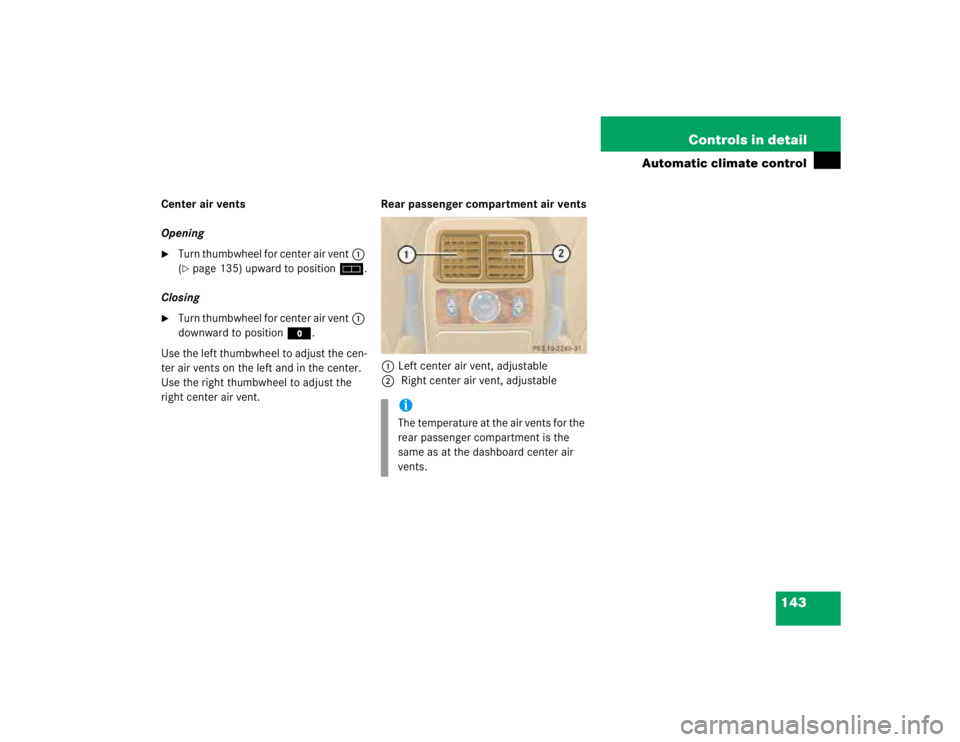
right center air vent.Rear passenger compartment air vents
1Left center air vent, adjustable
2 Right center air vent, adjustable
iThe temperature at the air vents for the
rear passenger compartment is the
same as at the dashboard center air
vents.
Page 959 of 4133

155 Controls in detail
Driving systems
Warning indicators
The warning indicators show the distance
between the sensor and the obstacle. The
warning indicators for the front area are lo-
cated above the center air vents in the
dashboard. The warning indicator for the
rear area is located in the rear passenger
compartment lamp.
1Segments, left side of vehicle
2Segments, right side of vehicle
Each warning indicator has six yellow and
two red segments.The gear selector lever position deter-
mines which warning indicator is activat-
ed.
As soon as the sensors detect an obstacle,
one or more segments light up, depending
on the distance. An intermittent acoustic
warning will also sound as the seventh seg-
ment comes on and a constant acoustic
warning lasting a maximum of
three seconds will sound for the eighth
segment.
Selector lever
position
Warning indicator
D, R, N, P
Front area activated
R
Rear area activated
!If all red segments light up in the warn-
ing indicators, a dirty sensor or a ultra-
sonic signal could be the reason.�
Clean the sensors (
�page 237).
After cleaning the sensors, switch
the ignition on.
Page 3465 of 4133
 from instrument
panel at firewall
*BA68.10-
P-1001-
01A
10Remove paneling from A-pillar AR68.30-P-
4050")
Dashboard
Air conditioning system
8Remove wiper system AR82.30-P-
6400GH
9Remove nuts (5) from instrument
panel at firewall
*BA68.10-
P-1001-
01A
10Remove paneling from A-pillar AR68.30-P-
4050GH
11Remove plastic nuts on driver's side
at paneling below instrument panel
12Remove paneling on right in footwell AR68.30-P-
4010GH
13
Remove rubber covers on side at the
A-pillars and unscrew screws for
instrument panel at A-pillar (arrows)
*BA68.10-
P-1002-
01A
14Remove center console AR68.20-P-
2000GH
15Unscrew bolt (6) underneath the
instrument panel
*BA68.10-
P-1003-
01A
16Withdraw instrument panel to the
rear Bring in helper. Cushion front edge of
selector lever module so that lower edge of
instrument panel is not damaged.
17Turn instrument panel around so that
the back is accessible Do not overstretch interior wiring
harness.
18Detach outside temperature sensor
connector (B10/5x1)
19Disconnect cable from temperature
sensor to evaporator housing Installation: Ensure clean cable routing.
20Remove outside temperature sensor
(B10/5) from air duct 2 bolts.
21Install in the reverse order
22Inspect cooling system for leaks AR20.00-P-
1010HA
NumberDesignationModel Series 163
BA68.10-P-1001-01ANut, dashboard to firewallNM8
BA68.10-P-1002-01ABolt, dashboard to A-pillarNM19
BA68.10-P-1003-01ABolt, dashboard to transmission tunnelNM30
NumberDesignationModel Series 163
BA83.30-P-1003-01BNut to pipeline on expansion valveNM10
2001 Mercedes-Benz ML320
1998-2005 HVAC Climate Control - 163 Chassis
me
Saturday, October 02, 2010 3:23:19 PMPage 221 © 2006 Mitchell Repair Information Company, LLC.
Page 3512 of 4133
AR54.65-P-0003GH
Removing and installing Parktronic system (PTS) warning display in instrument
panel
23.4.01
MODEL
163.113 /128 /154 /157 /174 /175 with CODE (220a) Parktronic System (PTS)
P54.65-2414-11
1
Connector
A44/4
PTS warning display, center of instrument panel
Remove/install
1
Remove PTS warning display (center of
dashboard)A44/4) above the instrument panel.
Ensure that the instrument panel is not
damaged.
Long wedge
*115589035900
2
Disconnect connector (1).
3
Install in the reverse order
Long wedge
115 589 03 59 00
Copyright DaimlerChrysler AG 09.05.2006 CD-Ausgabe G/10/04 . This WIS print-out will not be recorde
d by Modification services.
Page 1
Page 3562 of 4133
Instrument panel
Fig. 40: Identifying Torx Bit Set (000 589 01 10 00)
DISASSEMBLING AND ASSEMBLING CENTER CONSOLE - AR68.20-P-2150GH
MODEL 163.113 /136 /154 /172 /174 up to 31.8.01
18
Remove bracket between
instrument panel center part and
transmission tunnel
*BA68.10-P-
1003-01A
19Pull out floor covering (1) in area
of C-pillar and remove
Do not damage electrical leads.
Installation: Align floor covering at
attachment points for seats and thread electric
wires through corresponding cutouts.
20Install in the reverse order
NumberDesignationMODEL Series 163
BA68.10-P-1003-01AScrew, dashboard to transmission tunnelNm30
2001 Mercedes-Benz ML320
1998-2005 ACCESSORIES & BODY, CAB Interior Equipment - 163 Chassis
me
Saturday, October 02, 2010 3:35:22 PMPage 44 © 2006 Mitchell Repair Information Company, LLC.
 warning display in instrument
panel
23.4.01
MODEL
163.113 /128 /154 /157 /174 /175 with CODE (220a) Parktronic System (PTS)
P54")

DISASSEMBLING AND ASSEMBLING CENTER CONSOLE - AR68.20-P-2150GH
MODEL 163.113 /136 /154 /172 /174 up to 31.8.01
18
Remove brac")