1997 MERCEDES-BENZ ML430 climate settings
[x] Cancel search: climate settingsPage 3299 of 4133
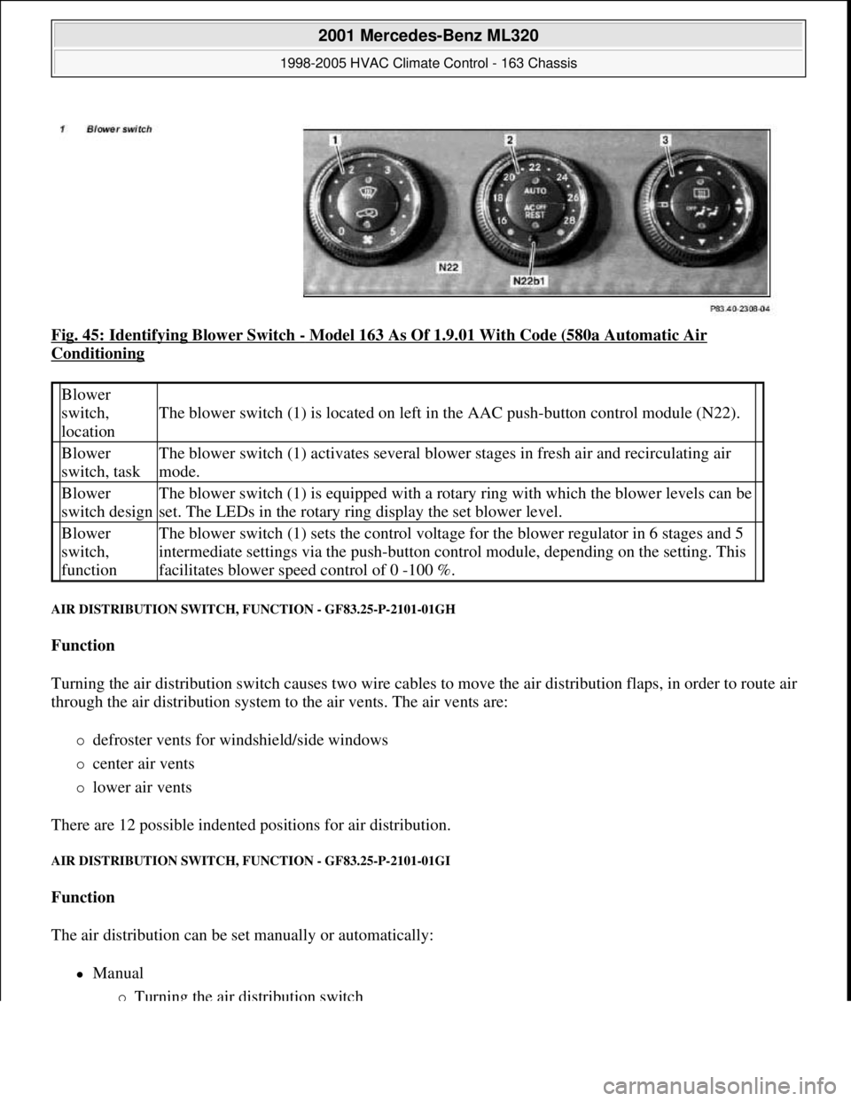
Fig. 45: Identifying Blower Switch - Model 163 As Of 1.9.01 With Code (580a Automatic Air
Conditioning
AIR DISTRIBUTION SWITCH, FUNCTION - GF83.25-P-2101-01GH
Function
Turning the air distribution switch causes two wire cables to move the air distribution flaps, in order to route air
through the air distribution system to the air vents. The air vents are:
defroster vents for windshield/side windows
center air vents
lower air vents
There are 12 possible indented positions for air distribution.
AIR DISTRIBUTION SWITCH, FUNCTION - GF83.25-P-2101-01GI
Function
The air distribution can be set manually or automatically:
Manual
Turning the air distribution switch
Blower
switch,
location
The blower switch (1) is located on left in the AAC push-button control module (N22).
Blower
switch, taskThe blower switch (1) activates several blower stages in fresh air and recirculating air
mode.
Blower
switch designThe blower switch (1) is equipped with a rotary ring with which the blower levels can be
set. The LEDs in the rotary ring display the set blower level.
Blower
switch,
functionThe blower switch (1) sets the control voltage for the blower regulator in 6 stages and 5
intermediate settings via the push-button control module, depending on the setting. This
facilitates blower speed control of 0 -100 %.
2001 Mercedes-Benz ML320
1998-2005 HVAC Climate Control - 163 Chassis
me
Saturday, October 02, 2010 3:23:15 PMPage 55 © 2006 Mitchell Repair Information Company, LLC.
Page 3300 of 4133
Automatic
Pressing the Auto button ( )
Turning the air distribution switch on the AAC push-button control modul e (N22) actuates the various air
distribution actuators via air conditioner bus.
The following basic settings for air distribution are provided:
Air flow from center and side vents
Air flow at center, side,
footwell and defroster vents
Air outlet at the center, side and defroster vents
Air flow at center, side and footwell vents
Apart from the 4 listed basic settings, a furt her 8 intermediate settings can be selected.
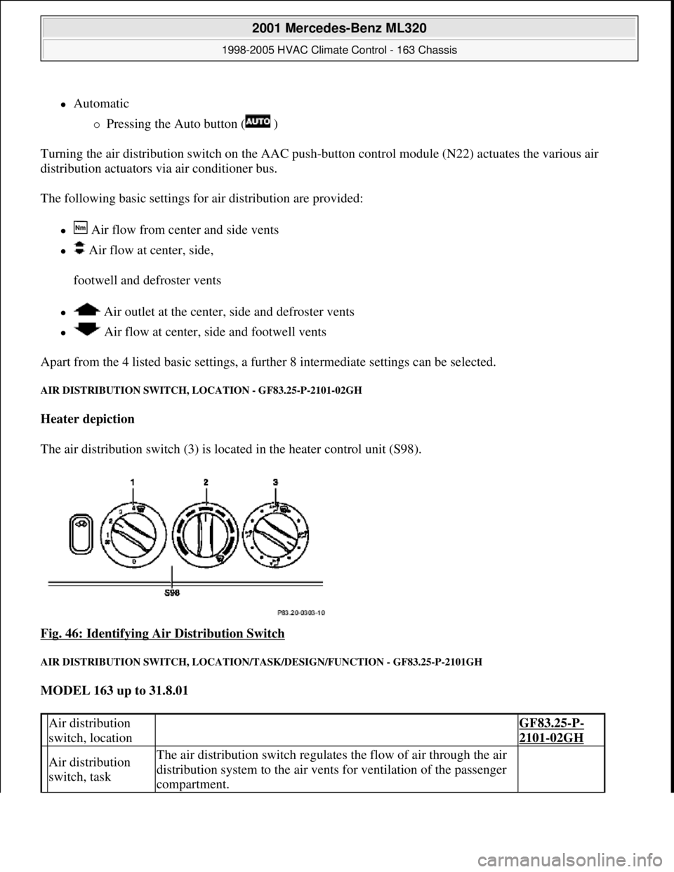
AIR DISTRIBUTION SWITCH, LOCATION - GF83.25-P-2101-02GH
Heater depiction
The air distribution switch (3) is loca ted in the heater control unit (S98).
Fig. 46: Identifying Ai r Distribution Switch
AIR DISTRIBUTION SWITCH , LOCATION/TASK/DESIGN/F UNCTION - GF83.25-P-2101GH
MODEL 163 up to 31.8.01
Air distribution
switch, location GF83.25-P-
2101-02GH
Air distribution
switch, taskThe air distribution switch regulates the flow of air through the air
distribution system to the air vent s for ventilation of the passenger
compartment.
2001 Mercedes-Benz ML320
1998-2005 HVAC Climate Control - 163 Chassis
me
Saturday, October 02, 2010 3:23:15 PMPage 56 © 2006 Mitchell Repair Information Company, LLC.
Page 3309 of 4133
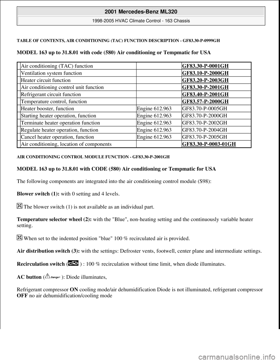
TABLE OF CONTENTS, AIR CONDITIONING (TAC) FUNCTION DESCRIPTION - GF83.30-P-0999GH
MODEL 163 up to 31.8.01 with code (580) Air conditioning or Tempmatic for USA
AIR CONDITIONING CONTROL MODULE FUNCTION - GF83.30-P-2001GH
MODEL 163 up to 31.8.01 with CODE (580) Air conditioning or Tempmatic for USA
The following components are integrated into the air conditioning control module (S98):
Blower switch (1): with 0 setting and 4 levels.
The blower switch (1) is not available as an individual part.
Temperature selector wheel (2): with the "Blue", non-heating setting and the continuously variable heater
setting.
When set to the indented position "blue" 100 % recirculated air is provided.
Air distribution switch (3): with the settings: Defroster vents, footwell, center plane and intermediate settings.
Recirculation switch ( ) : 100 % recirculation without time limit, when diode illuminates.
AC button ( ): Diode illuminates,
Refrigerant compressor ON cooling mode/air dehumidification Diode is not illuminated, refrigerant compressor
OFF no air dehumidification/coolin
g mode
Air conditioning (TAC) function GF83.30-P-0001GH
Ventilation system function GF83.10-P-2000GH
Heater circuit function GF83.20-P-2003GH
Air conditioning control unit function GF83.30-P-2001GH
Refrigerant circuit function GF83.40-P-2001GH
Temperature control, function GF83.57-P-2000GH
Heater booster, functionEngine 612.963GF83.70-P-0005GH
Starting heater operation, functionEngine 612.963GF83.70-P-2000GH
Terminate heater operation functionEngine 612.963GF83.70-P-2002GH
Regulate heater operation, functionEngine 612.963GF83.70-P-2004GH
Cancel heater operation, functionEngine 612.963GF83.70-P-2005GH
Air conditioning, location of components GF83.30-P-0003-01GH
2001 Mercedes-Benz ML320
1998-2005 HVAC Climate Control - 163 Chassis
me
Saturday, October 02, 2010 3:23:15 PMPage 65 © 2006 Mitchell Repair Information Company, LLC.
Page 3325 of 4133
The residual engine heat utilization system allows the vehicle to be heated even when the ignition is
switched OFF. To do so the system utilizes the residual heat from the engine and guides it via the
blower into the passenger compartment. The heating water circulation pump ensures that the
coolant is properly circulated.
Automatic air conditioning push-button control module
The automatic air conditioning can be operated by the driver using various tip switches. Apart from this
the push-
button control module reads in different sensor signals, processes them and controls components
in the automatic air conditioning.
Rear ventilation control panel
The operator can intervene in the automatic regulation of the rear ventilation through the automatic air
conditioning by using the rear ventilation control panel and adjust it accordingly to suit needs at any
given time. With the aid of the air distribution switch and blower switch the operator can accommodate
his/her own wishes. The correspondingly altered function is then no longer regulated by the automatic air
conditioning.
By pressing the automatic control button the manually initiated settings can be reset and thus regulated
again by the automatic air conditioning.
Regulation of the air quantity and air distribution ensues thus solely by way of the automatic air
conditioning push-button control module.
Heater circuit
Coolant is heated by the engine. Subsequently, the heated coolant is then routed through the heat exchanger,
where the heat is dissipated to the air in the passenger compartment. The heater return line, in which the heating
water circulation pump is located, takes the coolant back to the coolant pump.
The heating water circulation pump ensures that the coolant is properly circulated.
The coolant flows through the heat exchanger permanently.
Depending upon the desired in-car temperature, regulation is conducted over the blending air flaps, which are
operated by the blending air flap actuator motor.
Heater operation with heater booster in vehicles with OM 612.963
In vehicles equipped with direct-injection diesel engines, an electrical heater booster is additionally installed in
the evaporator housing downstream of the heat exchanger, in order to compensate the heater output deficit
which occurs in the case of certain operating conditions.
The 3 heating elements in the heater booster are supplied with current, as a result of which they are heated and
start to glow. As a result of the structural conditions, it is ensured that the drawn in fresh air flows directly past
the electric heater booster, and is therefore heated.
2001 Mercedes-Benz ML320
1998-2005 HVAC Climate Control - 163 Chassis
me
Saturday, October 02, 2010 3:23:16 PMPage 81 © 2006 Mitchell Repair Information Company, LLC.
Page 3333 of 4133
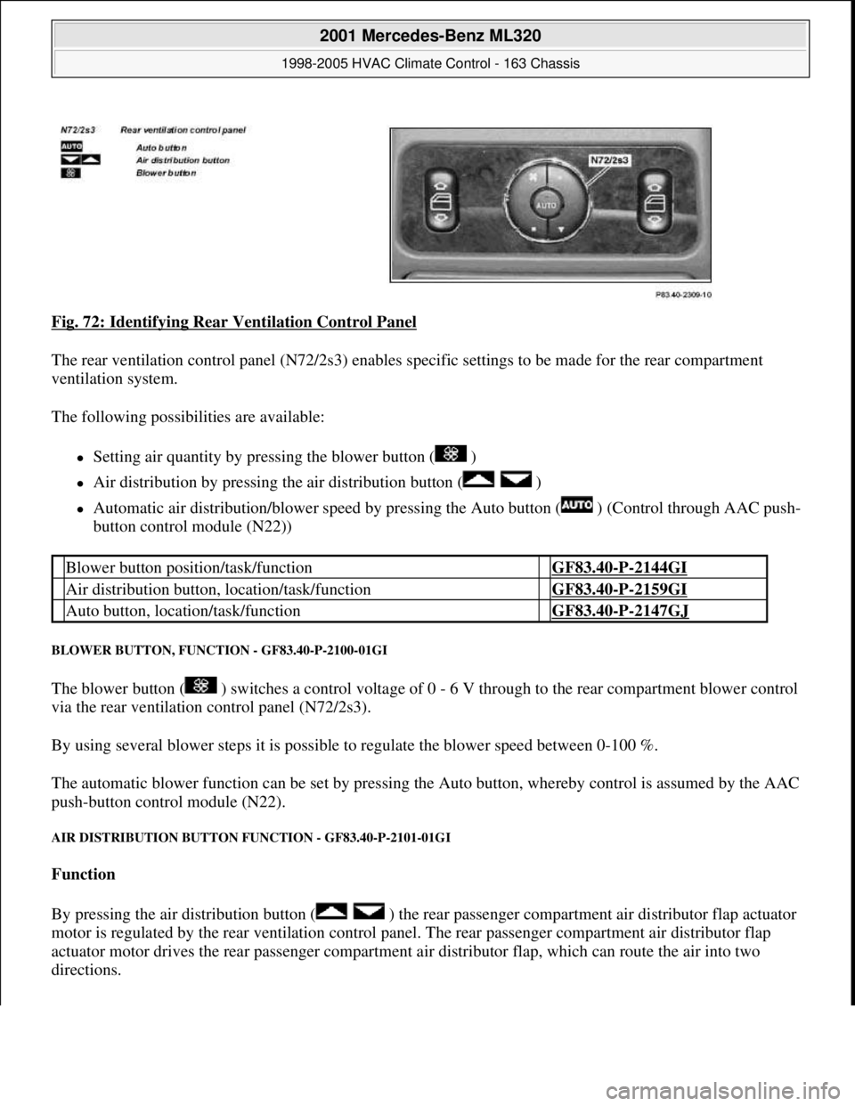
Fig. 72: Identifying Rear Ventilation Control Panel
The rear ventilation control panel (N 72/2s3) enables specific settings to be made for the rear compartment
ventilation system.
The following possibiliti es are available:
Setting air quantity by pressi ng the blower button ( )
Air distribution by pressing the air distribution button ( )
Automatic air distribution/blower speed by pressing the Auto button ( ) (Control through AAC push-
button control module (N22))
BLOWER BUTTON, FUNC TION - GF83.40-P-2100-01GI
The blower button ( ) switches a cont rol voltage of 0 - 6 V through to the rear compartment blower control
via the rear ventilation control panel (N72/2s3).
By using several blower steps it is possible to regulate the blower speed between 0-100 %.
The automatic blower function can be set by pressing th e Auto button, whereby control is assumed by the AAC
push-button control module (N22).
AIR DISTRIBUTION BUTTON FUNCTION - GF83.40-P-2101-01GI
Function
By pressing the air distribution button ( ) the rear pa ssenger compartment air distributor flap actuator
motor is regulated by the rear ventil ation control panel. The rear passenger compartment air distributor flap
actuator motor drives the rear passenger compartment ai r distributor flap, which can route the air into two
directions.
Blower button position/task/function GF83.40-P-2144GI
Air distribution button, location/task/function GF83.40-P-2159GI
Auto button, location/task/function GF83.40-P-2147GJ
2001 Mercedes-Benz ML320
1998-2005 HVAC Climate Control - 163 Chassis
me
Saturday, October 02, 2010 3:23:16 PMPage 89 © 2006 Mitchell Repair Information Company, LLC.
Page 3403 of 4133
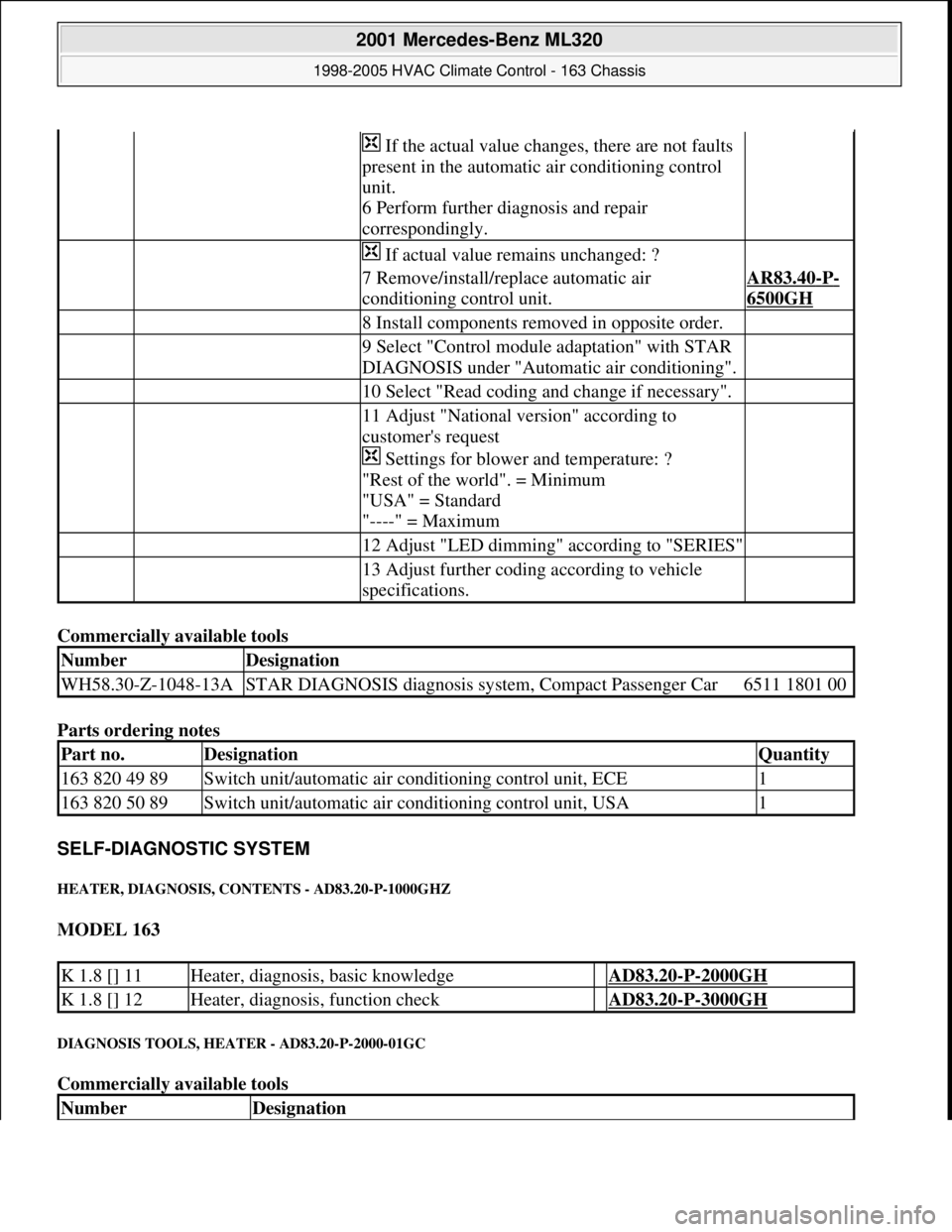
Commercially available tools
Parts ordering notes
SELF-DIAGNOSTIC SYSTEM
HEATER, DIAGNOSIS, CONTENTS - AD83.20-P-1000GHZ
MODEL 163
DIAGNOSIS TOOLS, HEATER - AD83.20-P-2000-01GC
Commercially available tools
If the actual value changes, there are not faults
present in the automatic air conditioning control
unit.
6 Perform further diagnosis and repair
correspondingly.
If actual value remains unchanged: ?
7 Remove/install/replace automatic air
conditioning control unit.AR83.40-P-
6500GH
8 Install components removed in opposite order.
9 Select "Control module adaptation" with STAR
DIAGNOSIS under "Automatic air conditioning".
10 Select "Read coding and change if necessary".
11 Adjust "National version" according to
customer's request
Settings for blower and temperature: ?
"Rest of the world". = Minimum
"USA" = Standard
"----" = Maximum
12 Adjust "LED dimming" according to "SERIES"
13 Adjust further coding according to vehicle
specifications.
NumberDesignation
WH58.30-Z-1048-13ASTAR DIAGNOSIS diagnosis system, Compact Passenger Car6511 1801 00
Part no.DesignationQuantity
163 820 49 89Switch unit/automatic air conditioning control unit, ECE1
163 820 50 89Switch unit/automatic air conditioning control unit, USA1
K 1.8 [] 11Heater, diagnosis, basic knowledge AD83.20-P-2000GH
K 1.8 [] 12Heater, diagnosis, function check AD83.20-P-3000GH
NumberDesignation
2001 Mercedes-Benz ML320
1998-2005 HVAC Climate Control - 163 Chassis
me
Saturday, October 02, 2010 3:23:17 PMPage 159 © 2006 Mitchell Repair Information Company, LLC.