Page 3255 of 4133
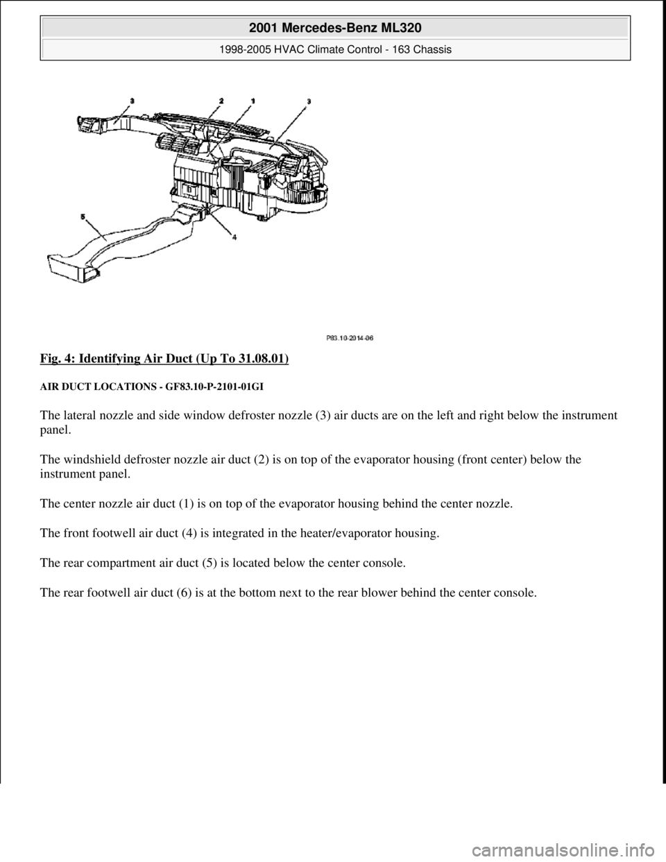
Fig. 4: Identifying Air Duct (Up To 31.08.01)
AIR DUCT LOCATIONS - GF83.10-P-2101-01GI
The lateral nozzle and side window defroster nozzle (3) air ducts are on the left and right below the instrument
panel.
The windshield defroster nozzle air duct (2) is on top of the evaporator housing (front center) below the
instrument panel.
The center nozzle air duct (1) is on top of the evaporator housing behind the center nozzle.
The front footwell air duct (4) is integrated in the heater/evaporator housing.
The rear compartment air duct (5) is located below the center console.
The rear footwell air duct (6) is at the bottom next to the rear blower behind the center console.
2001 Mercedes-Benz ML320
1998-2005 HVAC Climate Control - 163 Chassis
me
Saturday, October 02, 2010 3:23:14 PMPage 11 © 2006 Mitchell Repair Information Company, LLC.
Page 3256 of 4133
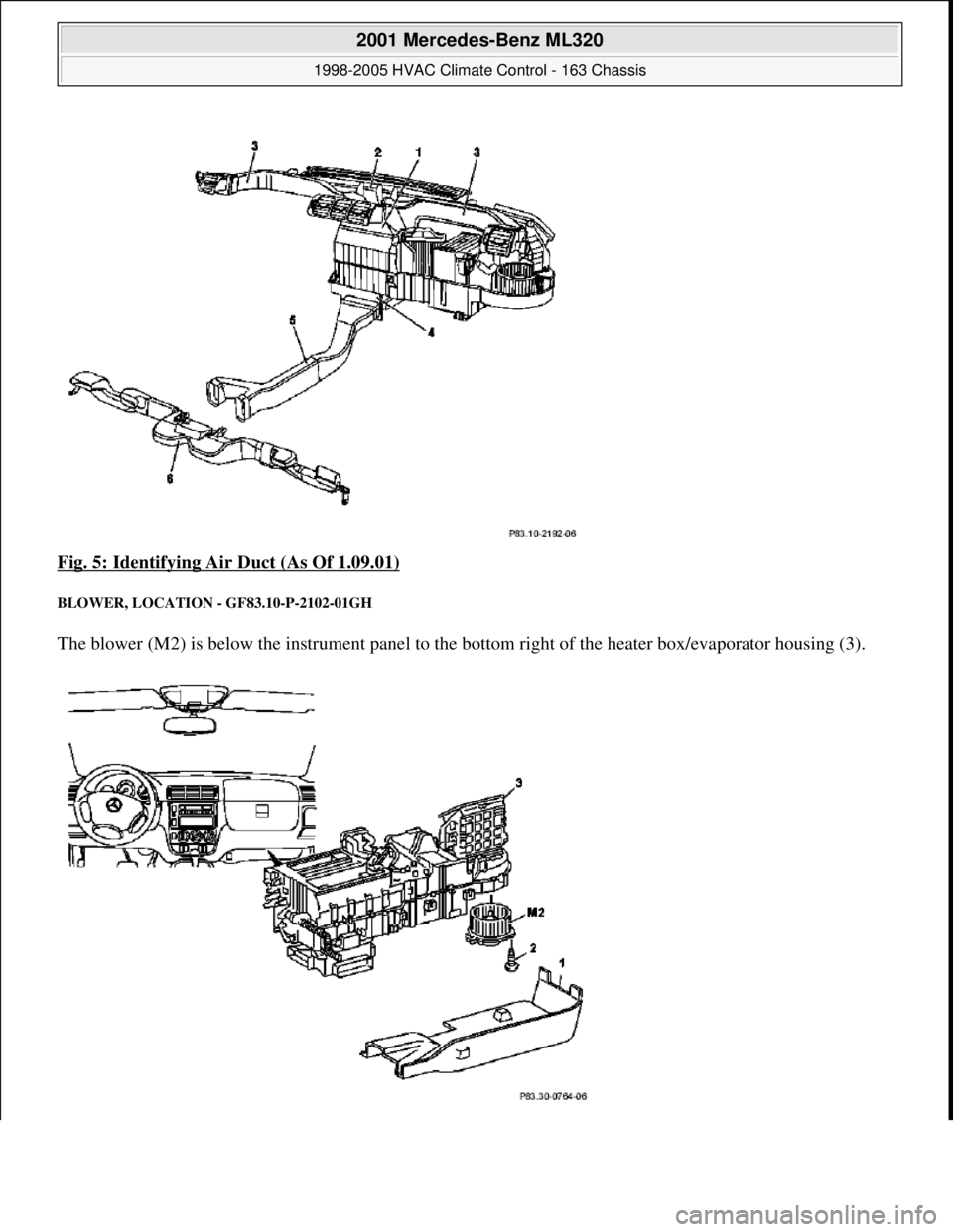
Fig. 5: Identifying Air Duct (As Of 1.09.01)
BLOWER, LOCATION - GF83.10-P-2102-01GH
The blower (M2) is below the instrument panel to th e bottom right of the heater box/evaporator housing (3).
2001 Mercedes-Benz ML320
1998-2005 HVAC Climate Control - 163 Chassis
me
Saturday, October 02, 2010 3:23:14 PMPage 12 © 2006 Mitchell Repair Information Company, LLC.
Page 3257 of 4133
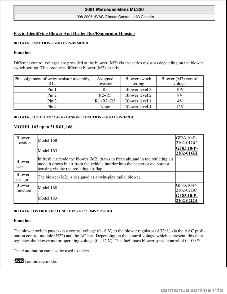
Fig. 6: Identifying Blower And Heater Box/Evaporator Housing
BLOWER, FUNCTION - GF83.10-P-2102-02GH
Function
Different control voltages are provided at the blower (M2) via the series resistors depending on the blower
switch setting. This produces different blower (M2) speeds.
BLOWER, LOCATION / TASK / DESIGN / FUNCTION - GF83.10-P-2102GC
MODEL 163 up to 31.8.01, 168
BLOWER CONTROLLER FUNCTION - GF83.10-P-2103-01GI
Function
The blower switch passes on a control voltage (0 - 6 V) to the blower regulator (A32n1) via the AAC push-
button control module (N22) and the AC bus. Depending on the control voltage which is present, this then
regulates the blower motor operating voltage (0 - 12 V). This facilitates blower speed control of 0-100 %.
The Auto button can also be used to select
( ) automatic mode.
Pin assignment of series resistor assembly
R14Assigned
resistorBlower switch
settingBlower (M2) control
voltage
Pin 1R3Blower level 310V
Pin 2R2+R3Blower level 28V
Pin 3R1+R2+R3Blower level 14V
Pin 4NoneBlower level 412V
Blower,
locationModel 168GF83.10-P-
2102-01GC
Model 163GF83.10-P-
2102-01GH
Blower,
taskIn fresh air mode the blower (M2) draws in fresh air, and in recirculating air
mode it draws in air from the vehicle interior into the heater or evaporator
housing via the recirculating air flap.
Blower
designThe blower (M2) is designed as a twin-pipe radial blower.
Blower,
functionModel 168GF83.10-P-
2102-02GC
Model 163GF83.10-P-
2102-02GH
2001 Mercedes-Benz ML320
1998-2005 HVAC Climate Control - 163 Chassis
me
Saturday, October 02, 2010 3:23:14 PMPage 13 © 2006 Mitchell Repair Information Company, LLC.
Page 3258 of 4133
The blower regulator then controls the blower motor operating voltage, depending on the actual measured in-car
temperature and the selected target temperature
(0-12 V). This facilitates blower speed control of 0-100 %.
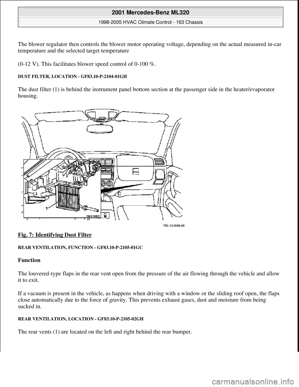
DUST FILTER, LOCATION - GF83.10-P-2104-01GH
The dust filter (1) is behind the instrument panel bottom section at the passenger side in the heater/evaporator
housing.
Fig. 7: Identifying Dust Filter
REAR VENTILATION, FUNCTION - GF83.10-P-2105-01GC
Function
The louvered-type flaps in the rear vent open from the pressure of the air flowing through the vehicle and allow
it to exit.
If a vacuum is present in the vehicle, as happens when driving with a window or the sliding roof open, the flaps
close automatically due to the force of gravity. This prevents exhaust gases, dust and moisture from being
sucked in.
REAR VENTILATION, LOCATION - GF83.10-P-2105-02GH
The rear vents (1) are located on the left and right behind the rear bumper.
2001 Mercedes-Benz ML320
1998-2005 HVAC Climate Control - 163 Chassis
me
Saturday, October 02, 2010 3:23:14 PMPage 14 © 2006 Mitchell Repair Information Company, LLC.
Page 3259 of 4133
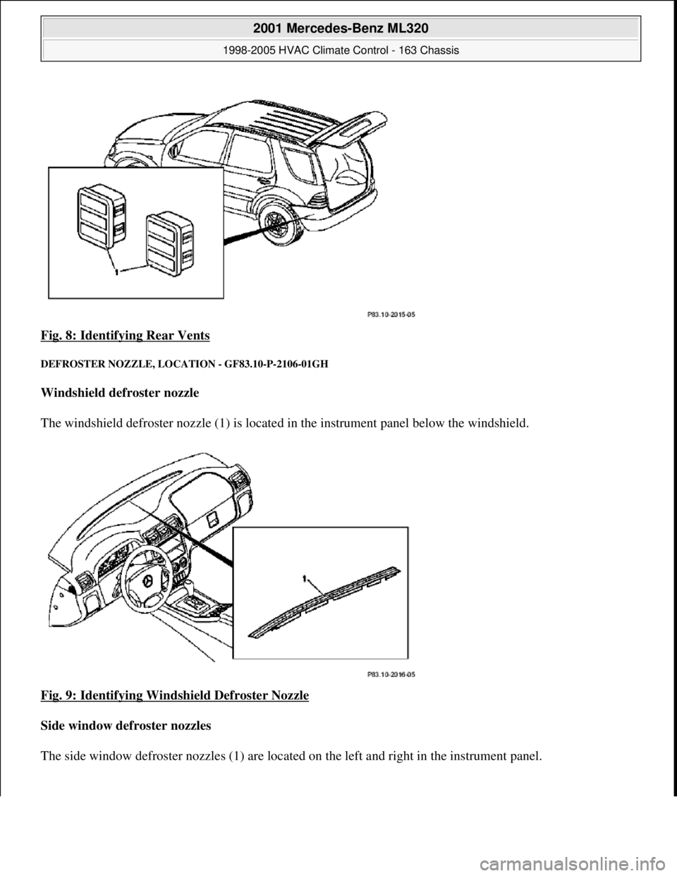
Fig. 8: Identifying Rear Vents
DEFROSTER NOZZLE, LOCATION - GF83.10-P-2106-01GH
Windshield defroster nozzle
The windshield defroster nozzle (1) is located in the instrument panel below the windshield.
Fig. 9: Identifying Windshield Defroster Nozzle
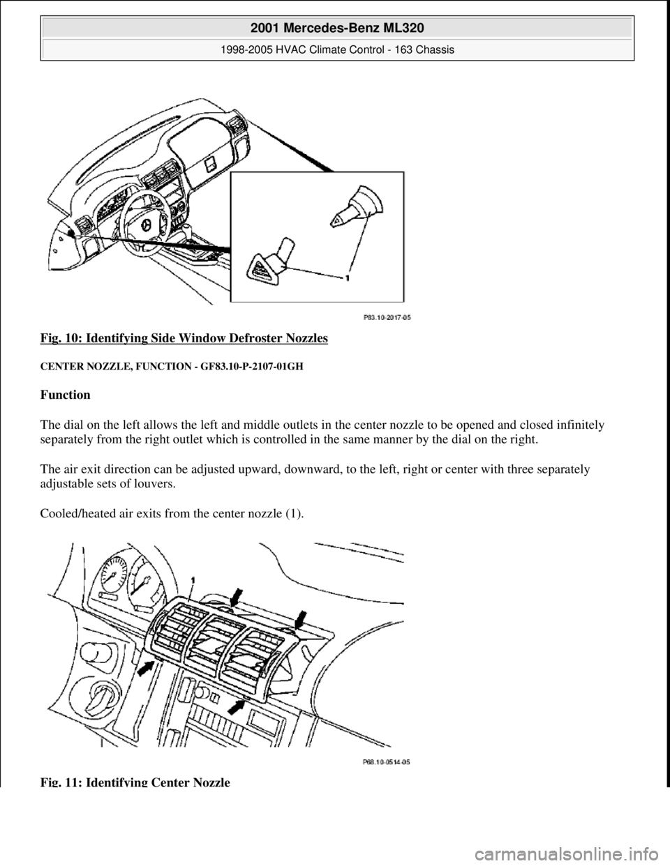
Side window defroster nozzles
The side window defroster nozzles (1) are located on the left and ri
ght in the instrument panel.
2001 Mercedes-Benz ML320
1998-2005 HVAC Climate Control - 163 Chassis
me
Saturday, October 02, 2010 3:23:14 PMPage 15 © 2006 Mitchell Repair Information Company, LLC.
Page 3260 of 4133
Fig. 10: Identifying Side Window Defroster Nozzles
CENTER NOZZLE, FUNC TION - GF83.10-P-2107-01GH
Function
The dial on the left allows the left and middle outlets in the center nozzle to be opened and closed infinitely
separately from the right outlet which is controll ed in the same manner by the dial on the right.
The air exit direction can be adjust ed upward, downward, to the left, right or center with three separately
adjustable sets of louvers.
Cooled/heated air exits from the center nozzle (1).
Fig. 11: Identifying Center Nozzle
2001 Mercedes-Benz ML320
1998-2005 HVAC Climate Control - 163 Chassis
me
Saturday, October 02, 2010 3:23:14 PMPage 16 © 2006 Mitchell Repair Information Company, LLC.
Page 3261 of 4133
CENTER NOZZLE, LOCA TION - GF83.10-P-2107-02GH
The center nozzle (1) is located above the center console in the instrument panel.
Fig. 12: Identifying Center Nozzle
SIDE NOZZLE, FUNCTI ON - GF83.10-P-2108-01GH
Function
The side nozzle (3) can be adjusted infinitely or opened and closed completely with the dial.
The air exit direction can be adjusted upward, downward, to the left, to the right or middle as desired with the
louver system.
Heated/cooled air exits th rough the side nozzle (3).
Fig. 13: Identifying Side Nozzle
SIDE NOZZLE, LOCATI ON - GF83.10-P-2108-02GH
2001 Mercedes-Benz ML320
1998-2005 HVAC Climate Control - 163 Chassis
me
Saturday, October 02, 2010 3:23:14 PMPage 17 © 2006 Mitchell Repair Information Company, LLC.
Page 3262 of 4133
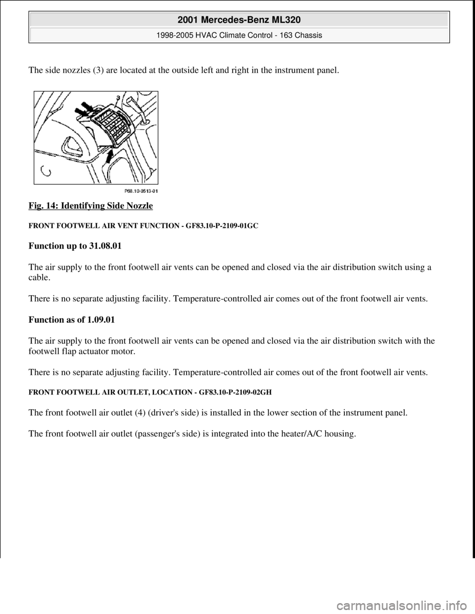
The side nozzles (3) are located at the outside left and right in the instrument panel.
Fig. 14: Identifying Side Nozzle
FRONT FOOTWELL AIR VENT FUNCTION - GF83.10-P-2109-01GC
Function up to 31.08.01
The air supply to the front footwell air vents can be opened and closed via the air distribution switch using a
cable.
There is no separate adjusting facility. Temperature-controlled air comes out of the front footwell air vents.
Function as of 1.09.01
The air supply to the front footwell air vents can be opened and closed via the air distribution switch with the
footwell flap actuator motor.
There is no separate adjusting facility. Temperature-controlled air comes out of the front footwell air vents.
FRONT FOOTWELL AIR OUTLET, LOCATION - GF83.10-P-2109-02GH
The front footwell air outlet (4) (driver's side) is installed in the lower section of the instrument panel.
The front footwell air outlet (passen
ger's side) is integrated into the heater/A/C housing.
2001 Mercedes-Benz ML320
1998-2005 HVAC Climate Control - 163 Chassis
me
Saturday, October 02, 2010 3:23:15 PMPage 18 © 2006 Mitchell Repair Information Company, LLC.