Page 1137 of 4133

333 Index
Reading lamps 114
Rear automatic climate control 141
Adjusting air volume and air distribu-
tion manually 141
Automatic mode 141
Rear bench seat
Foldable 99
Rear door window
Blocking operation 73
Rear fog lamp 267
Bulb 267
Switching on 111
Rear lamp bulbs
Replacing 270
Rear parking lamp
Replacing bulbs 270
Rear passenger compartment ventilation
and climate control
Activating 141
Deactivating 141
Rear passenger compartment ventilation
and rear automatic climate
control 141Rear quarter windows* 146
Opening 146
Closing 147
Rear seats 99
Easy entry/exit feature* 101
Enlarging cargo area 99
Folding down backrest 100
Folding up 101
Folding up backrest 100
Fore and aft 99
Lowering 100
Third row* 102
Rear standing lamp
Replacing bulbs 270
Rear towing eyes 285
Rear view mirror automatic antiglare 126
Rear view mirrors see Mirrors
Rear window defroster 133
Activating 133
Deactivating 133Rear window wiper 131
Rain sensor* 131
Rear window wiper/washer 51
Reconnecting
Vehicle battery 279
Refrigerant
Air conditioning 302
Refueling 214
Regular checks 215
Reinstalling vehicle battery 279
Remote control
Changing battery 262
Global locking 89
Global unlocking 89
Synchronizing 263
Unlocking liftgate 89
Unlocking the driver’s door, fuel filler
flap 89
Unlocking with 32
Remote control with folding key 88
Page 1778 of 4133
Fig. 186: Identifying Rain Sensor Components
Modification notes
11.4.03Disconnecting ground
lead from battery newly
includedStep 1
Remove/Install
1Disconnect ground
cable of battery AR54.10-P-0003A
2Remove rearview
mirror (1).Models 163.154/172#A up to
145272, Models 163.154/172#X up
to 708318AR68.40-P-0001GH
Models 163.154/172#A as of
145273, Models 163.154/172#X as
of 708319, Models
163.113/128/157/174/175AR68.40-P-0001GI
3Disconnect electrical
connector (2) from
rain sensor(B38)
4Press retaining lugs
(arrows) downward
5Remove rain sensor
(B38) Lens of rain sensor (B38) is
bonded to the windshield and may
2001 Mercedes-Benz ML320
1998-2005 ACCESSORIES & BODY, CAB Electrical System - Body - 163 Chassis
me
Saturday, October 02, 2010 3:30:09 PMPage 283 © 2006 Mitchell Repair Information Company, LLC.
Page 1788 of 4133
Fig. 194: Identifying Microphone Components
REMOVE/INSTALL LOUDSPEAKER AMPLIFIER CONTROL MODULE - AR82.62-P-7720GH
MODELS 163.113 /128 /136 /154 /157 /172 /175 with CODE (810) Sound system
MODEL 163.174
Removal/installation
1Remove inside rearview mirror AR68.40-P-0001GI
2Unclip plug from bracket
3Remove sound amplifier (B25/6)
microphone Do not damage
wiring harness.
Withdraw
microphone from
above.
4Install in the reverse order
5Check sound amplifier
microphone (B25/6) AR82.62-P-1110GH
2001 Mercedes-Benz ML320
1998-2005 ACCESSORIES & BODY, CAB Electrical System - Body - 163 Chassis
me
Saturday, October 02, 2010 3:30:09 PMPage 293 © 2006 Mitchell Repair Information Company, LLC.
Page 2067 of 4133

GF72.29-P-2002GH
Convenience control, function
7.4.97
MODEL
163
The convenience control allows the driver to operate the electrical
seat adjustment, the power windows, the electric vent windows, the
electric outside rearview mirror as well as the electric sliding/pop-up
roof or the electric lamella sliding roof
when the ignition is switched
off.
To achieve this, the all-activity module (AAM) (N10) switches to the
corresponding loads via the convenience relay (F1k14)
circuit 30 .
As of 12.99 the vehicle is equipped with its own convenience relay for
seat adjustment (relay 1, F2k1). In addition the status of the
convenience control via CAN is transmitted to the extended activity
module (EAM, N10/1).
Conditions for control actuation
On all-activity module (AAM) (N10) configured for
I
up
to
11.99:
The convenience actuation becomes active as soon as
D
Circuit 15 ON is recognized
When circuit 15 is switched off, the convenience actuation is
deactivated after a door is opened
Otherwise
The convenience actuation is active in the following cases:
D
Circuit 15c ON
D
A front door is open
D
The remote control key is removed, however, the doors are not
yet opened
In both cases the convenience actuation remains active for 5 min.
Switch-on condition for circuit 15c
When the remote control key is inserted into the ignition lock, circuit
15c is switched on when the key is turned out of the zero position.
Circuit 15c switches off only after the remote control key is removed
from the ignition lock
Electric seat adjustment without memory,
function
GF91.29-P-0003GH
Electric seat adjustment with memory, function
as of 12.99
GF91.29-P-0002GH
Convenience control, function
for electrical seat adjustment as of 12.99
GF91.29-P-2013GK
Power windows, function
GF72.29-P-0003GH
Power tilting/sliding roof (SR), function
GF77.20-P-0001GH
Electrically adjustable outside rearview
mirrors, function
GF88.79-P-0005GH
Electric vent windows, function
GF67.39-P-1000GH
Extended activity module,
location/purpose/design
as of 12.99
GF54.21-P-4107GK
Copyright DaimlerChrysler AG 04.08.2006 CD-Ausgabe G/10/04 . This WIS print-out will not be recorde
d by Modification services.
Page 1
Page 2119 of 4133
AR88.70-P-9060GH
Removing and installing mirror adjustment motor
12.2.97
MODEL
163
P88.70-0256-04
1
Screw
2
Connector
M21/1
Left electrically adjustable and heated
exterior rearview mirror
M21/2
Right electrically adjustable and
heated exterior rearview mirror (not
illustrated)
Operation no. of operation texts or of standard texts and flat rates
Division
Operation
no.
Operation text
P
883476
REPLACING MOTOR FOR LEFT ELECTRICALLY ADJUSTABLE EXTERIOR REARVIEW MIRROR
P
883478
REPLACING MOTOR FOR RIGHT ELECTRICALLY ADJUSTABLE EXTERIOR REARVIEW MIRROR
Removal, installation
1
Remove covering on outside rearview mirror
Remove mirror housing covering only.
AR88.70-P-9040GH
2
Unscrew screw (1)
3
Disconnect connector (2) and remove mirror
adjustment motor (M21/1 or M21/2)
4
Install in opposite order
Copyright DaimlerChrysler AG 09.05.2006 CD-Ausgabe G/10/04 . This WIS print-out will not be recorde
d by Modification services.
Page 1
Page 2120 of 4133

AR88.70-P-9040GH
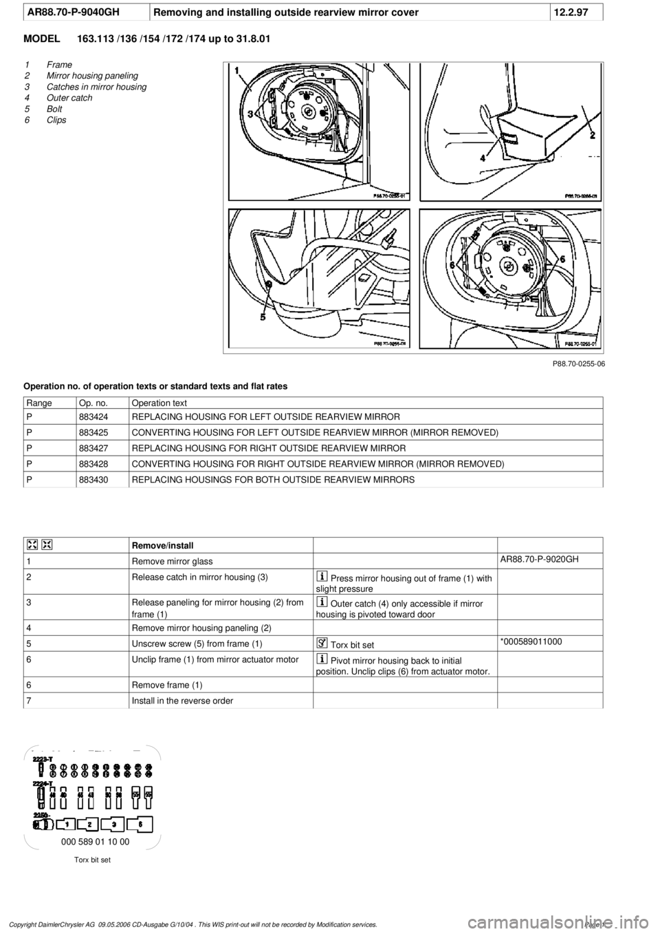
Removing and installing outside rearview mirror cover
12.2.97
MODEL
163.113 /136 /154 /172 /174 up to 31.8.01
P88.70-0255-06
1
Frame
2
Mirror housing paneling
3
Catches in mirror housing
4
Outer catch
5
Bolt
6
Clips
Operation no. of operation texts or standard texts and flat rates
Range
Op. no.
Operation text
P
883424
REPLACING HOUSING FOR LEFT OUTSIDE REARVIEW MIRROR
P
883425
CONVERTING HOUSING FOR LEFT OUTSIDE REARVIEW MIRROR (MIRROR REMOVED)
P
883427
REPLACING HOUSING FOR RIGHT OUTSIDE REARVIEW MIRROR
P
883428
CONVERTING HOUSING FOR RIGHT OUTSIDE REARVIEW MIRROR (MIRROR REMOVED)
P
883430
REPLACING HOUSINGS FOR BOTH OUTSIDE REARVIEW MIRRORS
Remove/install
1
Remove mirror glass
AR88.70-P-9020GH
2
Release catch in mirror housing (3)
Press mirror housing out of frame (1) with
slight pressure
3
Release paneling for mirror housing (2) from
frame (1)
Outer catch (4) only accessible if mirror
housing is pivoted toward door
4
Remove mirror housing paneling (2)
5
Unscrew screw (5) from frame (1)
Torx bit set
*000589011000
6
Unclip frame (1) from mirror actuator motor
Pivot mirror housing back to initial
position. Unclip clips (6) from actuator motor.
6
Remove frame (1)
7
Install in the reverse order
Torx bit set
000 589 01 10 00
Copyright DaimlerChrysler AG 09.05.2006 CD-Ausgabe G/10/04 . This WIS print-out will not be recorde
d by Modification services.
Page 1
Page 2121 of 4133

AR88.70-P-9020GH
Removing and installing mirror glass
12.2.97
MODEL
163.113 /136 /154 /172 /174 up to 31.8.01
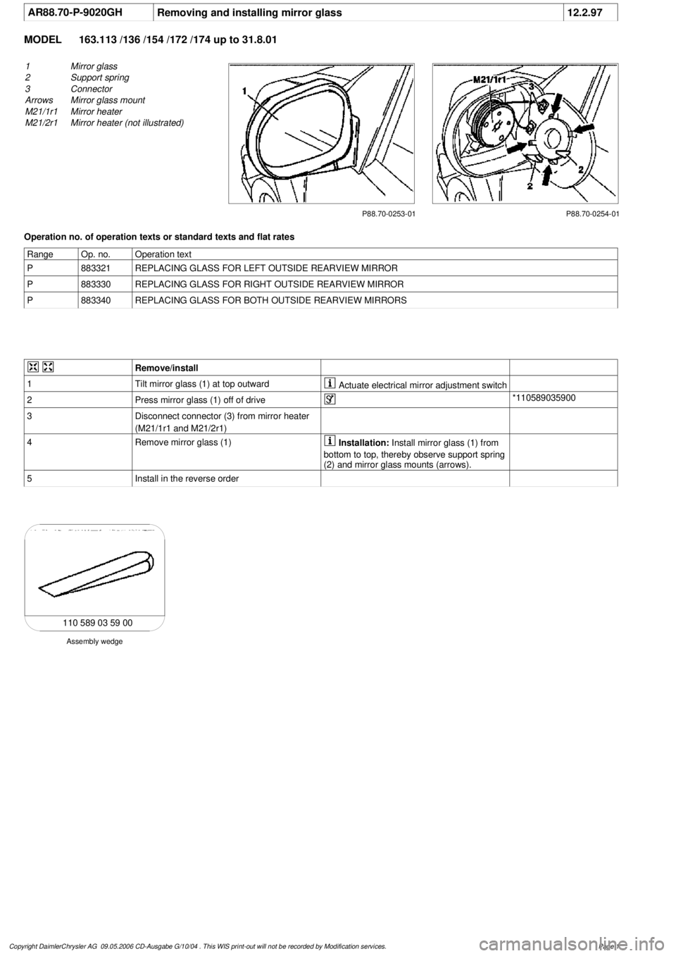
P88.70-0253-01
1
Mirror glass
2
Support spring
3
Connector
Arrows
Mirror glass mount
M21/1r1
Mirror heater
M21/2r1
Mirror heater (not illustrated)
P88.70-0254-01
Operation no. of operation texts or standard texts and flat rates
Range
Op. no.
Operation text
P
883321
REPLACING GLASS FOR LEFT OUTSIDE REARVIEW MIRROR
P
883330
REPLACING GLASS FOR RIGHT OUTSIDE REARVIEW MIRROR
P
883340
REPLACING GLASS FOR BOTH OUTSIDE REARVIEW MIRRORS
Remove/install
1
Tilt mirror glass (1) at top outward
Actuate electrical mirror adjustment switch
2
Press mirror glass (1) off of drive
*110589035900
3
Disconnect connector (3) from mirror heater
(M21/1r1 and M21/2r1)
4
Remove mirror glass (1)
Installation:
Install mirror glass (1) from
bottom to top, thereby observe support spring
(2) and mirror glass mounts (arrows).
5
Install in the reverse order
Assembly wedge
110 589 03 59 00
Copyright DaimlerChrysler AG 09.05.2006 CD-Ausgabe G/10/04 . This WIS print-out will not be recorde
d by Modification services.
Page 1
Page 2122 of 4133

AR88.70-P-9000GH
Remove/install complete outside rearview mirror
12.2.97
MODEL
163.113 /128 /136 /154 /157 /172 /174 /175
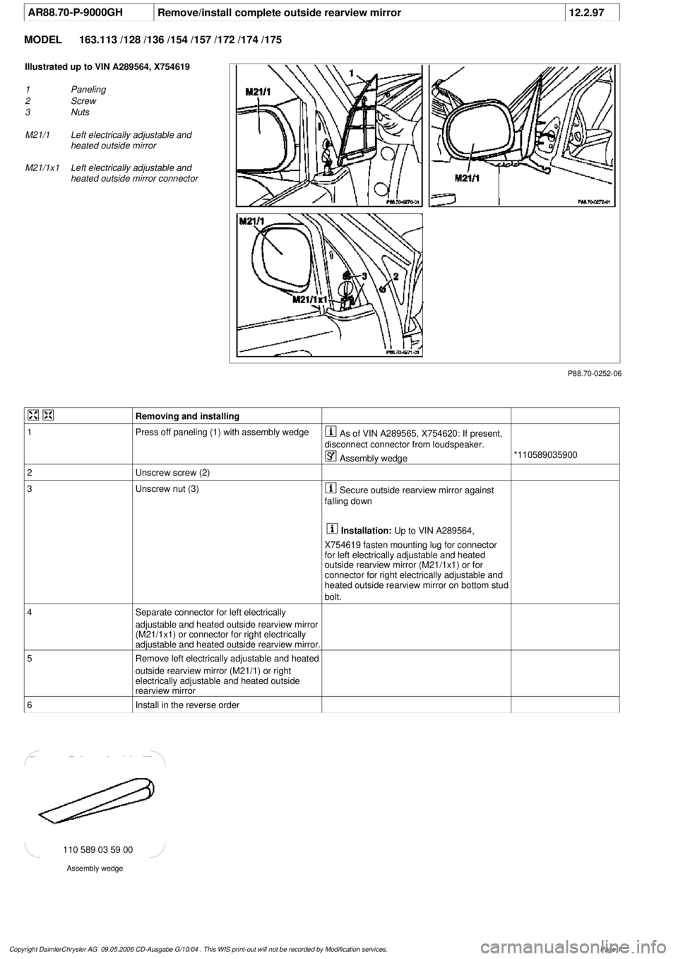
P88.70-0252-06
Illustrated up to VIN A289564, X754619
1
Paneling
2
Screw
3
Nuts
M21/1
Left electrically adjustable and
heated outside mirror
M21/1x1
Left electrically adjustable and
heated outside mirror connector
Removing and installing
1
Press off paneling (1) with assembly wedge
As of VIN A289565, X754620: If present,
disconnect connector from loudspeaker.
Assembly wedge
*110589035900
2
Unscrew screw (2)
3
Unscrew nut (3)
Secure outside rearview mirror against
falling down
Installation:
Up to VIN A289564,
X754619 fasten mounting lug for connector
for left electrically adjustable and heated
outside rearview mirror (M21/1x1) or for
connector for right electrically adjustable and
heated outside rearview mirror on bottom stud
bolt.
4
Separate connector for left electrically
adjustable and heated outside rearview mirror
(M21/1x1) or connector for right electrically
adjustable and heated outside rearview mirror.
5
Remove left electrically adjustable and heated
outside rearview mirror (M21/1) or right
electrically adjustable and heated outside
rearview mirror
6
Install in the reverse order
Assembly wedge
110 589 03 59 00
Copyright DaimlerChrysler AG 09.05.2006 CD-Ausgabe G/10/04 . This WIS print-out will not be recorde
d by Modification services.
Page 1