1997 MERCEDES-BENZ ML350 lights
[x] Cancel search: lightsPage 2080 of 4133
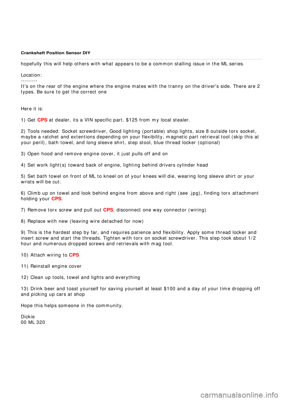
Crankshaft Position Sensor DIY
hopefully this will help others with what appears to be a common stalling issue in the ML series.
Location:
--------
It's on the rear of the engine where the engine mates with the tranny on the driver's side. There are 2
types. Be sure to get the correct one
Here it is:
1) Get
CPS
at dealer, its a VIN specific part. $125 from my local stealer.
2) Tools needed: Socket screwdriver, Good lighting (portable) shop lights, size 8 outside torx socket,
maybe a ratche
t and extentions depending on your flexibility, magnetic part retrieval tool (skip this at
your peril), bath towel, and long sleeve shirt, step stool, blue thread locker (optional)
3) Open hood and remove engine cover, it just pulls off and on
4) Set wor
k light(s) toward back of engine, lighting behind drivers cylinder head
5) Set bath towel on front of ML to kneel on of your knees will die, wearing long sleeve shirt or your
wrists will be cut.
6) Climb up on towel and look behind engine from above and
right (see .jpg), finding torx attachment
holding your
CPS
.
7) Remove torx screw and pull out
CPS
, disconnect one way connector (wiring)
8) Replace with new (leaving wire detached for now)
9) This is the hardest step by far, and requires patience and fl exibility. Apply some thread locker and
insert screw and start the threads. Tighten with torx on socket screwdriver. This step took about 1/2
hour and numerous dropped screws and retrievals with mag tool.
10) Attach wiring to
CPS
11) Reinstall engine cov
er
12) Clean up tools, towel and lights and everything
13) Drink beer and toast yourself for saving yourself at least $100 and a day of your time dropping off
and picking up cars at shop
Hope this helps someone in the community.
Dickie
00 ML 32
0
Page 2139 of 4133

GF54.21-P-4106-01GH
Extended Activity Module - Task
n
The primary tasks of the Extended Activity Module (EAM, N10/1) are
as follows:
D
To control the door sill lights
D
To suppress the auto-dimming mirror function
D
To control the headlight cleaning system (HCS)
D
To control the rear window defroster
D
To control seat heating
D
To control the power supply via control console to tilt/sliding or
louvered sunroof switch
D
To control the PTC heater booster (R22/3)
D
To control the auxiliary fan (M4)
D
To read the cruise control switch (S40) and relay data to control
module (DAS, N73/1)
D
To read the contacts for wiper speed settings 1 and 2 on
combination switch (S4) for diagnosis.
To perform these tasks the Extended Activity Module (EAM, N10/1)
reads various signals and switch settings directly.
The Extended Activity Module (EAM, N10/1) interfaces with other
control modules via the engine compartment CAN.
-----------------------------------------------------------------------------------------
Diagnosis
Diagnosis is performed using the Star diagnostic tool. To facilitate
this task, the Extended Activity Module (EAM, N10/1) is equipped
with its own diagnostics cable.
This cable is also used to diagnose the
All Activity Module (AAM,
N10)
and the
transfer case control module (N78)
.
The Extended Activity Module (EAM, N10/1) is linked to the All
Activity Module (AAM, N10) via the
engine compartment CAN
.
Data communication between the All Activity Module (AAM,
N10) and the Extended Activity Module (EAM, N10/1) is
assumed by the
CAN (N10 - N10/1)
when terminal 15 is off.
The CAN (N10 - N10/1)
is an independent CAN bus located
between the All Activity Module (AAM, N10) and the Extended
Activity Module (EAM, N10/1).
No other
control modules are
connected to the CAN (N10 - N10/1).
-----------------------------------------------------------------------------------------
Details:
Door sill lights
When the front interior light is on and one of the front doors is open,
or when the rear interior light is on and one of the back doors is open,
the door sill lights for the open door will illuminate.
Headlight cleaning system (HCS)
Activating a separate switch causes the EAM to send a turn-on signal
to the HCS pump relay.
EAM will send an additional turn-on signal to the HCS pump relay
only after the cleaning operation is completed and a "rest period" of
approximately 2.5 sec. has passed.
Auto-dimming mirror function
The auto-dimming mirror function is suppressed when the interior
light is on or reverse gear is engaged.
Auto-dimming suppression for the outside rearview mirror (slave) is
activated by the inside rearview mirror (master).
Heater booster/PTC air heater for diesel engines
EAM monitors system voltage and adjusts heater booster capacity to
minimize load on battery.
Rear window defroster
EAM sets maximum ON time for rear window defroster depending
on outdoor temperature and current vehicle speed.
D
Standard ON time:
10 min.
D
Outdoor temperature < 5
o
C:
Additional 5 min.
D
Speed >80 km/h:
Additional 3 min.
Seat heating
Sets maximum seat heating time.
D
Setting 1: max. 20 min.
D
Setting 2: max. 5 min.
Tilt/sliding or louvered sunroofs
Signal via AAM2 allows operation of tilt/sliding or louvered sunroofs
when ignition is on (standard mode) or off (keyless mode).
Ignition authorization via CAN
The EAM issues ignition authorization to AAM2 via the engine
compartment CAN depending on the requirements of the engine
control unit in connection with the FBM.
Copyright DaimlerChrysler AG 18.05.2006 CD-Ausgabe G/10/04 . This WIS print-out will not be recorde
d by Modification services.
Page 1
Page 2152 of 4133
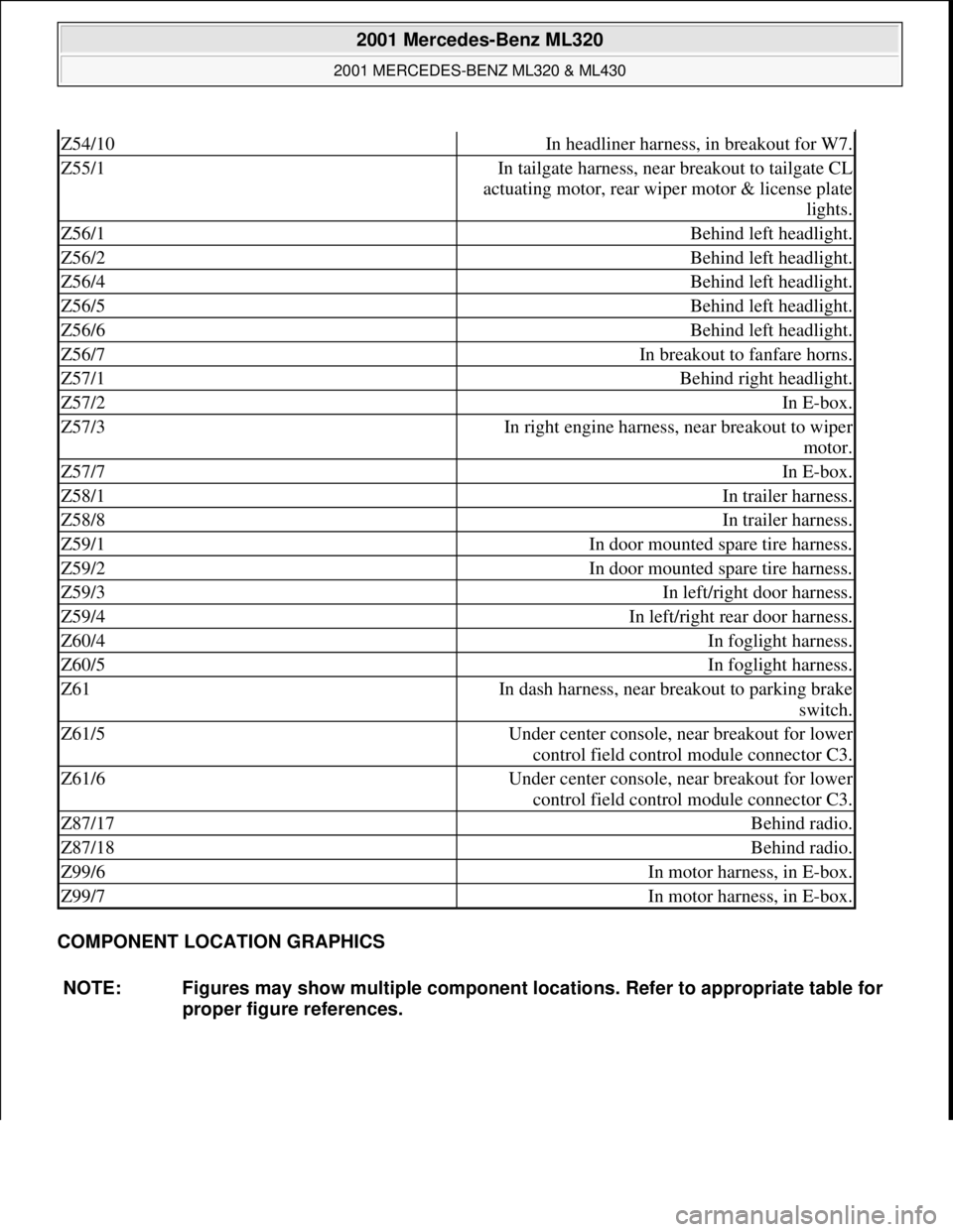
COMPONENT LOCATION GRAPHICS
Z54/10In headliner harness, in breakout for W7.
Z55/1In tailgate harness, near breakout to tailgate CL
actuating motor, rear wiper motor & license plate
lights.
Z56/1Behind left headlight.
Z56/2Behind left headlight.
Z56/4Behind left headlight.
Z56/5Behind left headlight.
Z56/6Behind left headlight.
Z56/7In breakout to fanfare horns.
Z57/1Behind right headlight.
Z57/2In E-box.
Z57/3In right engine harness, near breakout to wiper
motor.
Z57/7In E-box.
Z58/1In trailer harness.
Z58/8In trailer harness.
Z59/1In door mounted spare tire harness.
Z59/2In door mounted spare tire harness.
Z59/3In left/right door harness.
Z59/4In left/right rear door harness.
Z60/4In foglight harness.
Z60/5In foglight harness.
Z61In dash harness, near breakout to parking brake
switch.
Z61/5Under center console, near breakout for lower
control field control module connector C3.
Z61/6Under center console, near breakout for lower
control field control module connector C3.
Z87/17Behind radio.
Z87/18Behind radio.
Z99/6In motor harness, in E-box.
Z99/7In motor harness, in E-box.
NOTE: Figures may show multiple component locations. Refer to appropriate table for
proper figure references.
2001 Mercedes-Benz ML320
2001 MERCEDES-BENZ ML320 & ML430
me
Saturday, October 02, 2010 3:21:17 PMPage 12 © 2006 Mitchell Repair Information Company, LLC.
Page 3232 of 4133
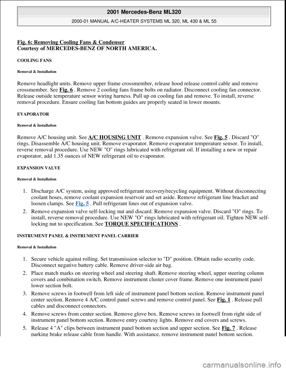
Fig. 6: Removing Cooling Fans & Condenser
Courtesy of MERCEDES-BENZ OF NORTH AMERICA.
COOLING FANS
Removal & Installation
Remove headlight units. Remove upper frame crossmember, release hood release control cable and remove
crossmember. See Fig. 6
. Remove 2 cooling fans frame bolts on radiator. Disconnect cooling fan connector.
Release outside temperature sensor wiring harness. Pull up on cooling fan and remove. To install, reverse
removal procedure. Ensure cooling fan bottom guides are properly seated in lower mounts.
EVAPORATOR
Removal & Installation
Remove A/C housing unit. See A/C HOUSING UNIT . Remove expansion valve. See Fig. 5 . Discard "O"
rings. Disassemble A/C housing unit. Remove evaporator. Remove evaporator temperature sensor. To install,
reverse removal procedure. Use NEW "O" rings lubricated with refrigerant oil. If installing a new or repair
evaporator, add 1.35 ounces of NEW refrigerant oil to evaporator.
EXPANSION VALVE
Removal & Installation
1. Discharge A/C system, using approved refrigerant recovery/recycling equipment. Without disconnecting
coolant hoses, remove coolant expansion reservoir and set aside. Remove refrigerant line bracket and
loosen clamps. See Fig. 5
. Pull refrigerant lines out of expansion valve.
2. Remove expansion valve self-locking nut and discard. Remove expansion valve. Discard "O" rings. To
install, reverse removal procedure. Use NEW "O" rings lubricated with refrigerant oil. Tighten NEW self-
locking nut to specification. See TORQUE SPECIFICATIONS
.
INSTRUMENT PANEL & INSTRUMENT PANEL CARRIER
Removal & Installation
1. Secure vehicle against rolling. Set transmission selector to "D" position. Obtain radio security code.
Disconnect negative battery cable. Remove driver-side air bag.
2. Place match marks on steering wheel and steering shaft. Remove steering wheel, upper steering column
covers and combination switch. Remove instrument cluster cover frame. Remove one instrument panel
lower section bolt.
3. Remove screws in footwell from left side of instrument panel bottom section. Remove instrument panel
center section. Remove 4 A/C control panel screws and remove control panel. See Fig. 1
. Release pull
cables and disconnect connectors.
4. Remove screws from center section. Remove glove box. Remove screws in footwell from right side of
instrument panel bottom section. Remove entry courtesy lights. Remove end covers and screws.
5. Release 4 "A" clips between instrument panel bottom section and upper section. See Fig. 7
. Release
parkin
g brake release cable from handle. With assistance, remove instrument panel bottom section.
2001 Mercedes-Benz ML320
2000-01 MANUAL A/C-HEATER SYSTEMS ML 320, ML 430 & ML 55
me
Saturday, October 02, 2010 3:25:10 PMPage 21 © 2006 Mitchell Repair Information Company, LLC.
Page 3480 of 4133

GF54.30-P-2001A
Indicator / warning displays, function
24.10.96
MODEL
129, 140 as of 1.6.96,
163, 168, 170,
202 as of 1.8.96,
208 up to 31.7.99,
210 as of 1.6.96 up to 30.6.99
The table below lists the various warning alarms and indications
according to type (visual/acoustic) and their actuation (direct/CAN).
Visual warning and indicator signals actuated over direct lines:
D
Left turn signal indicator lamp (A1e1)
D
Right turn signal indicator lamp (A1e2)
D
High beam indicator lamp (A1e3)
D
Fuel reserve warning lamp (A1e4)
D
Brake fluid / parking brake warning lamp (A1e7) (except model
163)
D
Low windshield washer fluid level warning lamp (A1e13) (as of
01.09.01 also valid for model 163)
D
Low engine coolant level warning lamp (A1e11) (except model
168, model 163 as of 3.99)
D
Coolant level and temperature warning lamp (A1e11) (only model
168 as of 9.99 and only coolant level function)
D
Generator charge indicator/warning lamp (A1e5)
D
Seat belt warning lamp (A1e9)
D
Seatbelt/backrest lock warning lamp (A1e9)
D
Exterior lamp failure indicator lamp (A1e14)
-----------------------------------------------------------------------------------------
D
Hydraulic fluid level warning lamp (A1e37)
D
ADS warning lamp, suspension (A1e27)
D
Steering lock warning lamp (A1e40) (only
I
)
D
SRS airbag malfunction indicator lamp (A1e15)
D
AIRBAG OFF indicator lamp (A1e56), only model 163 except
I
Also refer to document: Indicator and warning signals triggered
over CAN data lines
Acoustic warning and indicator signals actuated over direct
lines:
D
Turn signal ticker
D
Seat belt reminder
D
Switched-on lights reminder
D
Key warning
D
Soft top warning, only model 170
Also refer to document: Acoustic warnings, function
Acoustic warning and indicator signals actuated over CAN data
lines:
D
Parking brake warning
D
Vehicle speed warning
D
Vehicle speed limit warning
D
Gear warning, only model 168
Also refer to document: Acoustic warnings, function
Indicator and warning signals triggered over
direct lines
GF54.30-P-3002A
Indicator and warning signals triggered over
CAN data lines
GF54.30-P-3003A
Acoustic warnings, function
GF54.30-P-3010A
Copyright DaimlerChrysler AG 04.06.2006 CD-Ausgabe G/10/04 . This WIS print-out will not be recorde
d by Modification services.
Page 1
Page 3481 of 4133

GF54.30-P-2001A
Indicator / warning displays, function
24.10.96
MODEL
129, 140 as of 1.6.96,
163, 168, 170,
202 as of 1.8.96,
208 up to 31.7.99,
210 as of 1.6.96 up to 30.6.99
The table below lists the various warning alarms and indications
according to type (visual/acoustic) and their actuation (direct/CAN).
Visual warning and indicator signals actuated over direct lines:
D
Left turn signal indicator lamp (A1e1)
D
Right turn signal indicator lamp (A1e2)
D
High beam indicator lamp (A1e3)
D
Fuel reserve warning lamp (A1e4)
D
Brake fluid / parking brake warning lamp (A1e7) (except model
163)
D
Low windshield washer fluid level warning lamp (A1e13) (as of
01.09.01 also valid for model 163)
D
Low engine coolant level warning lamp (A1e11) (except model
168, model 163 as of 3.99)
D
Coolant level and temperature warning lamp (A1e11) (only model
168 as of 9.99 and only coolant level function)
D
Generator charge indicator/warning lamp (A1e5)
D
Seat belt warning lamp (A1e9)
D
Seatbelt/backrest lock warning lamp (A1e9)
D
Exterior lamp failure indicator lamp (A1e14)
-----------------------------------------------------------------------------------------
D
Hydraulic fluid level warning lamp (A1e37)
D
ADS warning lamp, suspension (A1e27)
D
Steering lock warning lamp (A1e40) (only
I
)
D
SRS airbag malfunction indicator lamp (A1e15)
D
AIRBAG OFF indicator lamp (A1e56), only model 163 except
I
Also refer to document: Indicator and warning signals triggered
over CAN data lines
Acoustic warning and indicator signals actuated over direct
lines:
D
Turn signal ticker
D
Seat belt reminder
D
Switched-on lights reminder
D
Key warning
D
Soft top warning, only model 170
Also refer to document: Acoustic warnings, function
Acoustic warning and indicator signals actuated over CAN data
lines:
D
Parking brake warning
D
Vehicle speed warning
D
Vehicle speed limit warning
D
Gear warning, only model 168
Also refer to document: Acoustic warnings, function
Indicator and warning signals triggered over
direct lines
GF54.30-P-3002A
Indicator and warning signals triggered over
CAN data lines
GF54.30-P-3003A
Acoustic warnings, function
GF54.30-P-3010A
Copyright DaimlerChrysler AG 05.06.2006 CD-Ausgabe G/10/04 . This WIS print-out will not be recorde
d by Modification services.
Page 1
Page 3483 of 4133

GF54.30-P-3002A
Indicator and warning signals triggered over direct lines, function
24.10.96
MODEL
129, 140 as of 1.6.96,
163, 168, 170,
202 as of 1.8.96,
208 up to 31.7.99,
210 as of 1.6.96 up to 30.6.99
Indicator and warning signals
Indicator lamps for left turn signal (A1e1) and right turn signal
(A1e2)
The signal in models 129, 140, 170, 202 comes from the
combination relay (turn signals with trailer coupling, rear
window defroster, wiper motor, anti-theft alarm system)
(N10/2), and in model 210 from the multifunction control
module (N10-1) or the driver's side signal acquisition and
actuation module (SAM) (N10/1).
In model 168 the entire turn signal control is located in the
instrument cluster (A1).
Brake fluid / parking brake warning lamp (A1e7)
The signal for the brake fluid comes direct from the brake fluid level switch (S11) (except model 163).
(The signal for the parking brake comes over CAN.)
Low windshield washer fluid level warning lamp (A1e13) except
models 163 and 168
See
document: Coolant/washer fluid level voltage coding, task /
function
-----------------------------------------------------------------------------------------
Low windshield washer fluid level warning lamp (A1e13) as of
01.09.01 for model 163
See document: Displaying washer fluid level, function
Low engine coolant level warning lamp (A1e11) except models
163 and 168
See
document: Coolant/washer fluid level voltage coding, task /
function
Low engine coolant level warning lamp (A1e11) model 163 as of
3.99
See
document: Displaying coolant level, function
Coolant level and temperature warning lamp (A1e11) model 168
as of 9.99
See
document: Displaying coolant level, function
Fuel reserve warning lamp (A1e4)
When the reserve fuel level is reached, this lamp lights up and
goes out again only after refueling is detected. If the vehicle is
refueled with the ignition ON, refueling is detected only if at
least 7 liters of fuel are added.
-----------------------------------------------------------------------------------------
AIRBAG OFF indicator lamp (A1e56), only model 163 except
I
The signal comes from the emergency tensioning retractor
(ETR) control module with airbag (AB, N2/2)
Generator charge indicator/warning lamp (A1e5)
See document: Terminal 61 and terminal 61e, charge indicator
lamp, exterior lamp failure, function
Seatbelt/backrest lock warning lamp (A1e9)
The seat belt warning lamp is only used in a few national
versions, and is actuated direct by a seat belt buckle switch
(normally closed contact). After engine start, the lamp flashes
for a short time (approx. 6 seconds).
In model 129 if this lamp fails to go out after flashing briefly, but
continues to shine constantly, then the seat backrest is not
locked.
Exterior lamp failure indicator lamp (A1e14)
The signal comes from the lamp failure monitor
See document: Terminal 61 and terminal 61e, charge indicator
lamp, exterior lamp failure, function
Hydraulic fluid level warning lamp (A1e37)
The signal comes direct from the ADS level control oil level
switch (S44).
ADS warning lamp, suspension (A1e27) The signal comes from the ADS control module, suspension
(N51).
SRS airbag malfunction indicator lamp (A1e15)
The signal comes from the emergency tensioning retractor
(ETR) control module with airbag (AB, N2/2)
Voltage coding of coolant / windshield washer
fluid level, function
Except models 163 and 168
GF54.30-P-3006A
Displaying coolant level, function
Model 163 as of 3.99
GF54.30-P-3028GH
Model 168 as of 9.99
GF54.30-P-3028GC
Terminal 61 and terminal 61e, charge
indicator lamp, exterior lamp failure, function
GF54.30-P-3007A
Copyright DaimlerChrysler AG 04.06.2006 CD-Ausgabe G/10/04 . This WIS print-out will not be recorde
d by Modification services.
Page 1
Page 3736 of 4133
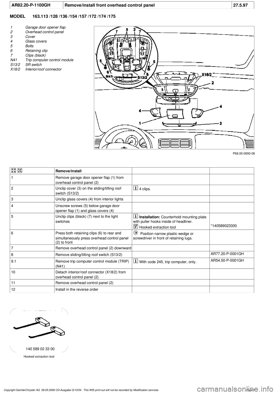
AR82.20-P-1100GH
Remove/install front overhead control panel
27.5.97
MODEL
163.113 /128 /136 /154 /157 /172 /174 /175
P68.00-0650-06
1
Garage door opener flap
2
Overhead control panel
3
Cover
4
Glass covers
5
Bolts
6
Retaining clip
7
Clips (black)
N41
Trip computer control module
S13/2
SR switch
X18/2
Interior/roof connector
Remove/install
1
Remove garage door opener flap (1) from
overhead control panel (2)
2
Unclip cover (3) on the sliding/tilting roof
switch (S13/2)
4 clips.
3
Unclip glass covers (4) from interior lights
4
Unscrew screws (5) below garage door
opener flap (1) and glass covers (4)
5
Unclip clips (black) (7) next to the light
switches
Installation:
Counterhold mounting plate
with puller hooks inside of headliner.
Hooked extraction tool
*140589023300
6
Press both retaining clips (6) to rear and
simultaneously press overhead control panel
(2) to front
Position narrow plastic wedge or
screwdriver in front of retaining lugs.
7
Remove overhead control panel (2) downward
8
Remove sliding/tilting roof switch (S13/2)
AR77.20-P-0001GH
9.1
Remove trip computer control module (TRIP)
(N41)
With code 245, trip computer, only.
AR54.50-P-0001GH
10
Detach interior/roof connector (X18/2) from
overhead control panel (2)
11
Remove overhead control panel (2)
12
Install in the reverse order
Hooked extraction tool
140 589 02 33 00
Copyright DaimlerChrysler AG 09.05.2006 CD-Ausgabe G/10/04 . This WIS print-out will not be recorde
d by Modification services.
Page 1