1997 MERCEDES-BENZ ML350 fuel cap
[x] Cancel search: fuel capPage 2612 of 4133
AR47.10-P-8022GH
Remove/install fuel tank pressure sensor
18.3.97
MODEL
163.154 with ENGINE 112.942 with CODE (494a) USA version
MODEL
163.157 with ENGINE 112.970 with CODE (494a) USA version
MODEL
163.172 with ENGINE 113.942 with CODE (494a) USA version
MODEL
163.174 with ENGINE 113.981 with CODE (494a) USA version
MODEL
163.175 with ENGINE 113.965 with CODE (494a) USA version
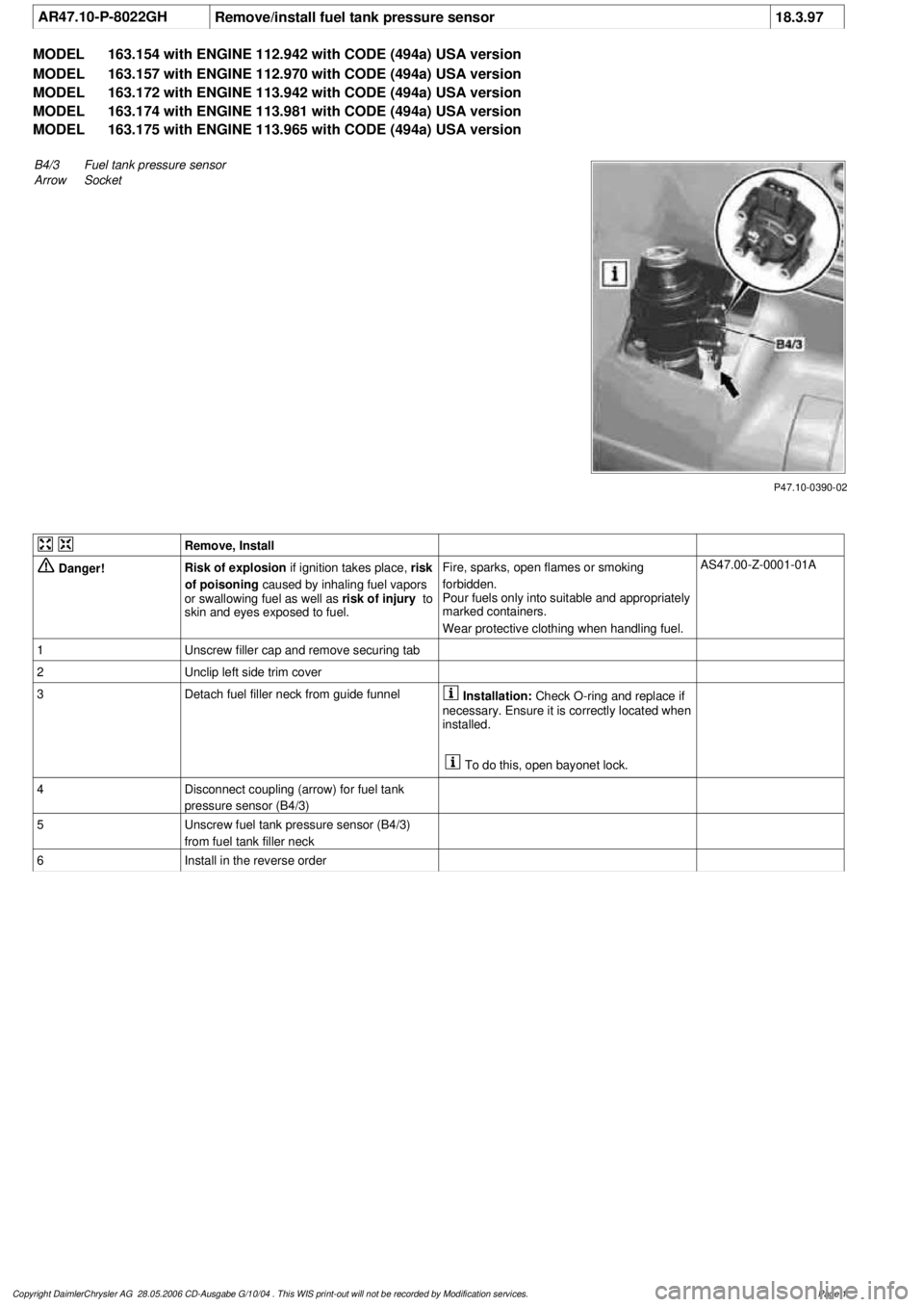
P47.10-0390-02
B4/3Fuel tank pressure sensor
Arrow
Socket
Remove, Install
Danger!
Risk of explosion
if ignition takes place,
risk
of poisoning
caused by inhaling fuel vapors
or swallowing fuel as well as
risk of injury
to
skin and eyes exposed to fuel.
Fire, sparks, open flames or smoking
forbidden.
Pour fuels only into suitable and appropriately
marked containers.
Wear protective clothing when handling fuel.
AS47.00-Z-0001-01A
1
Unscrew filler cap and remove securing tab
2
Unclip left side trim cover
3
Detach fuel filler neck from guide funnel
Installation:
Check O-ring and replace if
necessary. Ensure it is correctly located when
installed.
To do this, open bayonet lock.
4
Disconnect coupling (arrow) for fuel tank
pressure sensor (B4/3)
5
Unscrew fuel tank pressure sensor (B4/3)
from fuel tank filler neck
6
Install in the reverse order
Copyright DaimlerChrysler AG 28.05.2006 CD-Ausgabe G/10/04 . This WIS print-out will not be recorde
d by Modification services.
Page 1
Page 2613 of 4133
AR47.30-P-8200GH
Remove/install fuel vapor expansion reservoir
13.3.01
MODEL
163.113 #A as of 289565,
163.113 #X as of 754620,
163.154 #A as of 289565,
163.154 #X as of 754620,
163.128 /157 /175
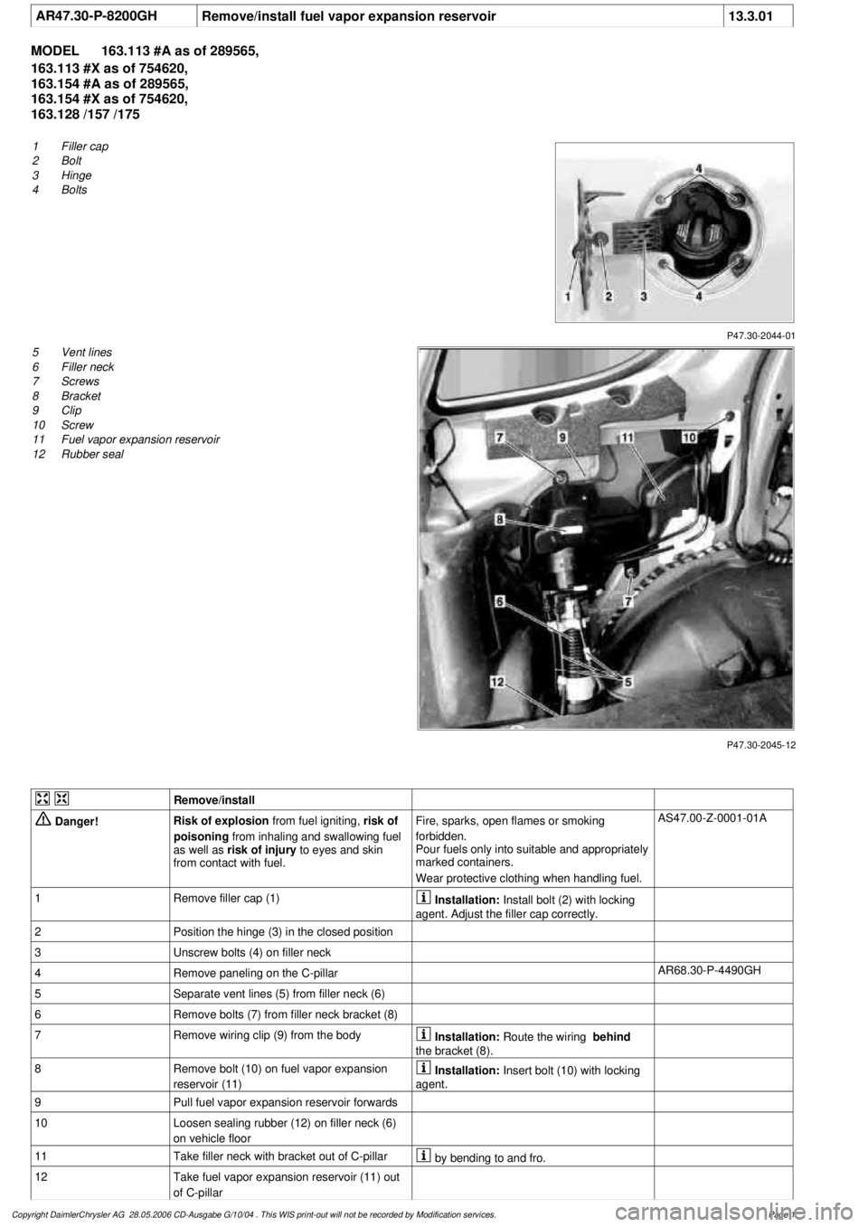
P47.30-2044-01
1
Filler cap
2
Bolt
3
Hinge
4
Bolts
P47.30-2045-12
5
Vent lines
6
Filler neck
7
Screws
8
Bracket
9
Clip
10
Screw
11
Fuel vapor expansion reservoir
12
Rubber seal
Remove/install
Danger!
Risk of explosion
from fuel igniting,
risk of
poisoning
from inhaling and swallowing fuel
as well as
risk of injury
to eyes and skin
from contact with fuel.
Fire, sparks, open flames or smoking
forbidden.
Pour fuels only into suitable and appropriately
marked containers.
Wear protective clothing when handling fuel.
AS47.00-Z-0001-01A
1
Remove filler cap (1)
Installation:
Install bolt (2) with locking
agent. Adjust the filler cap correctly.
2
Position the hinge (3) in the closed position
3
Unscrew bolts (4) on filler neck
4
Remove paneling on the C-pillar
AR68.30-P-4490GH
5
Separate vent lines (5) from filler neck (6)
6
Remove bolts (7) from filler neck bracket (8)
7
Remove wiring clip (9) from the body
Installation:
Route the wiring
behind
the bracket (8).
8
Remove bolt (10) on fuel vapor expansion
reservoir (11)
Installation:
Insert bolt (10) with locking
agent.
9
Pull fuel vapor expansion reservoir forwards
10
Loosen sealing rubber (12) on filler neck (6)
on vehicle floor
11
Take filler neck with bracket out of C-pillar
by bending to and fro.
12
Take fuel vapor expansion reservoir (11) out
of C-pillar
Copyright DaimlerChrysler AG 28.05.2006 CD-Ausgabe G/10/04 . This WIS print-out will not be recorde
d by Modification services.
Page 1
Page 3049 of 4133
CHECK ALL VISIBLE PARTS FOR SIGNS OF LEAKS AND DAMAGE - AP00.20-P-0053GH
MODEL 163.113 /128 /136 /154 /157 /172 /174 /175
INSPECTING CHASSIS AND LOAD-BEARING BODY PARTS FOR DAMAGE AND CORROSION - AP00.20-P-0090GH
MODEL 163
with Code Z04/Z07
Model 230AP00.20-P-0001L
Model 414AP00.20-L-0001A
Taxi serviceModels 202, 210AP00.20-P-0007A
Model 203AP00.20-P-0007C
Remove
Detach lower engine
compartment panelingModels 163.172/174/175AR61.20-P-1105GH
Remove noise
encapsulationModel 163.113/128AR94.30-P-5400GH
Check
2If traces of fluid are noted
(e.g. oil), then determine
and correct the cause (on a
separate work order).
Check for leaksEngine:
Transmission
Transfer case
Front axle
Rear axle
Pressure oil pump
3Check for leaks and fixingShock absorbers,
suspension struts
4Inspect for leaks and
conditionRubber boots of front axle
shafts
5Inspect lines and hoses for
leaks and condition, pay
attention to chafing points
and routingRadiator
Fuel system
Exhaust system
Clutch actuation
Automatic transmission
Power steering
Brake system
Install
Install lower engine
compartment paneling.Models 163.172/174/175AR61.20-P-1105GH
Install noise encapsulationModel 163.113/128AR94.30-P-5400GH
1Visual inspectionControl arm mountings and
control arms of front axle
2004 Mercedes-Benz ML350
1998-2005 GENINFO Overall vehicle - 163 Chassis
me
Saturday, October 02, 2010 3:47:52 PMPage 404 © 2006 Mitchell Repair Information Company, LLC.
Page 3720 of 4133
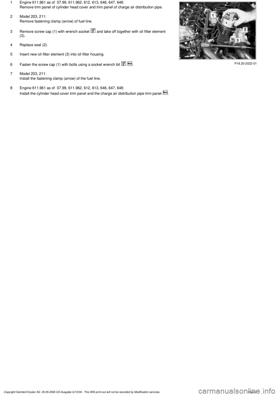
P18.20-2022-01
1
Engine 611.961 as of 07.99, 611.962, 612, 613, 646, 647, 648:
Remove trim panel of cylinder head cover and trim panel of charge air distribution pipe.
2
Model 203, 211:
Remove fastening clamp (arrow) of fuel line.
3
Remove screw cap (1) with wrench socket
and take off together with oil filter element
(3).
4
Replace seal (2).
5
Insert new oil filter element (3) into oil filter housing.
6
Fasten the screw cap (1) with bolts using a socket wrench bit
.
7
Model 203, 211:
Install the fastening clamp (arrow) of the fuel line.
8
Engine 611.961 as of 07.99, 611.962, 612, 613, 646, 647, 648:
Install the cylinder head cover trim panel and the charge air distribution pipe trim panel
.
Copyright DaimlerChrysler AG 20.05.2006 CD-Ausgabe G/10/04 . This WIS print-out will not be recorde
d by Modification services.
Page 2
Page 3835 of 4133

SI18.00-P-0010A
Service Information: oil sludge
26.3.01
ENGINE
111 in MODELS 124, 163, 170, 202, 203, 208, 210
ENGINE
112 in MODELS 129, 163, 170, 202, 203, 208, 210, 220
ENGINE
112, 113 in MODEL 463
ENGINE
113 in MODELS 129, 163, 202, 208, 210, 215, 220
ENGINE
137 in MODEL 215, 220
ENGINE
166 in MODEL 168
Oil sludging in gasoline engines with ASSYST maintenance
system
Recently we have determined that time and time again oil
sludging occurs in gasoline engines with an ASSYST maintenance
system.
Oil sludging can lead to the following complaints:
D
engine oil consumption
D
engine smoke (white/blue)
D
influencing of oil level indicator
D
clogged oil filter, engine oil thickened like jelly
D
Check engine lamp illuminated
D
oil sludge visible during assembly job, e.g. in oil filter, in cylinder
head covers, condensation sludging
(engine 166) etc.
-----------------------------------------------------------------------------------------
The following list of causes may lead individually or as a combination
to engine oil sludging:
D
Crankcase ventilation inoperable, function orifices, bores,
passages in cylinder head cover, cylinder head, crankcase etc.
are mechanically sealed. A nonfunctioning crankcase
ventilation boosts loads on the engine oil through organic
nitrates. The risk of oil sludging increases.
The mechanical condition of the engine is always to be
checked, i.e. all engine oil drain orifices on the cylinder head
and crankcase and all crankcase ventilation ducts must be free
of obstacles. Crankcase breather lines may not be kinked.
Check the ventilation bores in the cylinder head covers.
-----------------------------------------------------------------------------------------
D
The engine oil used does not comply with the specifications in
Sheet 229.1 or 229.3 of the Specifications for Service Products.
The additive process, e.g. dirt-carrying capability, neutralization
capability and oxidation resistance as well as the quality of the
base stock influence sludging time.
Use of engine oils with best possible resistance to formation of
sludge, i.e. use only tested and approved engine oils (from
Sheet 229.1 or 229.3). The best protection is afforded by the
engine oils on Sheet 229.3, which fulfill more stringent
specifications with regard to preventing sludge and deposits
(see Sheet 221.0, page 11). These oils have a distinctly better
anti-sludge characteristic than other engine oils.
D
Sludging after adding a fuel or engine oil special additive.
Do not use fuel or engine oil special additives. More information
hereto is available on Sheet 219.0 of the Specifications for
Service products. Reference to customer not to use special
additives.
D
Engine oil change not performed according to ASSYST
specifications. At driven distances
exceeding > approx. 3000 km, engine oil sludging may occur.
-----------------------------------------------------------------------------------------
Comply with engine oil and filter change as under ASSYST
specifications. Observe remaining distance.
D
Fuel grade lies outside standard (regionally contingent). If
contaminated, deficient fuel is used, then engine oil sludging
may occur even where approved engine oil is used.
Operation with fuel, e.g. as under DIN EN 228. Clarify refueling
behavior of customer. If engine operation regional, is
temporarily possible with deficient oil only, then the startup
distance has to be individually reduced, i.e. the oil change
temporarily performed at an interval of, e.g. 10,000 km.
D
Radiator antifreeze penetration into engine oil, e.g. through an
internal engine leak (cylinder head gasket, casting porosity).
The engine oil sludges within a short period. The crankcase
ventilation clogs up and stops functioning. Condensation
sludging clogs up the oil separator cells
(engine 166).
Rectify coolant leakage. Clean all sludged engine parts, in
particular the crankcase ventilation parts. If the occurrence
repeats, and casting porosity is suspected, e.g. replace
crankcase.
-----------------------------------------------------------------------------------------
Copyright DaimlerChrysler AG 20.05.2006 CD-Ausgabe G/10/04 . This WIS print-out will not be recorde
d by Modification services.
Page 1
Page 3854 of 4133
ENGINE 113.940 /941 /942 /943 /948 /960 /961 /963 /965 /966 /967 /968 /969
ENGINE 119.980 /981 /982 /985
ENGINE 137.970
Task
To allow safe further driving depending on the fault which has arisen in the electronic accelerator pedal system.
Pedal value sensor emergency mode
If the sensor in the pedal value sensor (B37) fails, the system will switch over to the second sensor. The throttle
valve opening is limited to approx. 60%. There is also dynamic limitation of the throttle valve's opening speed
where the throttle valve opening is delayed (the indicator lamp EPC does not light up).
If the plausibility check delivers a negative result or both sensors are defect only the idling speed will be
regulated (the indicator lamp EPC lights up).
Actuator for the throttle valve - emergency running, electrical
If a potentiometer in the actuator for the throttle valve breaks down the system switches-over to the second
intact potentiometer. The air flow mass serves as a second parameter for comparative purposes. Following a
plausibility check, the throttle valve opening is limited to approx. 60% in line with engine speed and load (EPC
indicator lamp does not come on).
If the plausibility check is negative or if both potentiometers are faulty, the throttle valve adopts a mechanical
emergency running position which is fixed by the spring capsule in the actuator (EPC indicator lamp comes on).
Actuator for the throttle valve - emergency running, mechanical emergency running stop
If the actuator motor is defect or there are other faults present the power supply to the actuator will be shut off.
The throttle valve then lies on the mechanical stop (spring box) so the throttle valve opening remains at a
constant 10-12°. At no engine load (idling) engine speed is regulated to about 900 rpm by shutting off or
activating the cylinders at the fuel side.
When driving, engine speed is controlled, in line with the engine load, by switching the cylinders off and on at
the fuel side. The maximum engine speed is about 1800 rpm. which is limited by the mechanical stop (the
indicator lamp EPC lights up).
Safety fuel shutoff
If a mechanical fault exists in the actuator, the safety fuel shutoff is activated.
Here the fuel injection valves are shut off for engine speeds < 1400 rpm and actuated again at speeds < 1200
rpm (the indicator lamp EPC li
ghts up).
2001 Mercedes-Benz ML320
1998-2005 ACCESSORIES & BODY CAB Throttle Control, Speed Control Systems - 163 Chassis
me
Saturday, October 02, 2010 3:36:27 PMPage 14 © 2006 Mitchell Repair Information Company, LLC.
Page 3891 of 4133
Fig. 4: Connecting Hand Held Tester Scan Tool To OBD-II Data Link Connector
Courtesy of MERCEDES-BENZ OF NORTH AMERICA.
TESTING
Starter malfunctions may cause a Di agnostic Trouble Codes (DTCs) to be stored in Motor Electronics
Sequential Fuel Injection (ME-SFI) sy stem. After repairs are completed check for and erase any DTCs stored in
(ME-SFI) system. See appropriate SE LF-DIAGNOSTICS article in ENGINE PERFORMANCE. If cause of
starter malfunction is not engine pe rformance related, replace starter.
REMOVAL & INSTALLATION
STARTER
Removal & Installation
1. Disconnect and shield negative battery cable. See BATTERY DISCONNECT/CONNECT under
SERVICE PRECAUTIONS.
2. Remove nut (2) for inner fender. See Fig. 5
. Pull front and rear section of inner fender (1) downward.
Move inner fender away inward and downward. Pull toward outside over wheel. DO NOT damage fender
cutout or paint.
3. On vehicles with 112 engine, remove nut (6) at shield (5) of left engine mount and take out shield. See
Fig. 6
.
4. On all vehicles, disconnect circuit 30 (1) and circuit 50 (2) cables from starter. See Fig. 6
. Remove bolts
(3) for starter-to-crankcase. Take starter (M1) out to the side.
5. If replacing starter on vehicles with manual transmission, check ring gear at flywheel for wear and
damage. If replacing starter on vehicles with auto matic transmission, check ring gear on drive plate for
wear and damage. Repair or repl ace damaged parts as necessary.
6. To install, reverse removal proce dure. Replace bolts with locking splines, micro-encapsulated bolts and
self-locking nuts. Mating thread of mi cro-encapsulated bolts must be cleaned to remove all residue of old
bolt locking compound. Tighten fasteners to specification. See TORQUE SPECIFICATIONS
. Connect
battery. See BATTERY DISCONNECT/CONNECTunder SERVICE PRECAUTIONS.
NOTE: Numbers and letters in text refe
r to numbers and letters in figures.
2001 Mercedes-Benz ML320
2001-04 STARTING & CHARGING SYSTEMS Starters - 163 Chassis
me
Saturday, October 02, 2010 3:19:47 PMPage 9 © 2006 Mitchell Repair Information Company, LLC.