1997 MERCEDES-BENZ ML350 fuel cap
[x] Cancel search: fuel capPage 2230 of 4133

1.1
Unscrew bolts at rear of 2/3 seat bench and
raise rear of seat bench
Up to VIN A145272, X708318.
1.2
Remove covers at seat frame of 60% bench
seat
As of VIN A145273, X708319.
AR91.12-P-1100GH
Only remove the covers which are
identified in the document with A, D and E.
2.1
Fold 60% bench seat forward into footwell
As of VIN A145273, X708319. See
operator's manual.
3.1
Pull floor covering below rear seat mounting
bracket (1) of 60% seat forward
Carefully pull floor covering forward under
the seat console to prevent it from tearing.
As of VIN A145273, X708319.
4.1
Pull the floor covering forward under the front
corner of the left C-pillar cover (2)
Carefully pull the floor covering forward
under the cover to prevent it from tearing.
As of VIN A145273, X708319.
5
Cut into floor covering directly behind seat
retaining cable (3)
Ensure that the wiring harness (4) is not
damaged when cutting the floor covering.
As of VIN A145273, X708319. Broken
line marks the cut.
6
Fold floor mat back
Do not crease floor mat!
Fold floor mat back far enough to provide
access to cap (84) between body and fuel
pump.
7
Remove end cover (84) of body
Installation:
Replace cap and insert with
new sealing compound.
Cap (84) is sealed in with body sealer.
Heat with hot air blower to make it easier to
remove.
8
Seal fuel return line (90/11)
Pliers
*163589003700
9
Connect extraction hose (90/14) with adapter
hose to connection for fuel return line (90/11)
Extraction hose
*168589009000
Adapter hose
*163589009100
10
Connect ground cable (90/10) of extraction
pump ground terminal vehicle battery
Pumping out
11
Pump fuel out into safety container using
extraction pump
*BF47.10-P-1001-01A
*WH58.30-Z-1001-16A
12
Install in the reverse order
Fuel tank
Number
Designation
Models
163.113/
136/154/
172 up to
31.08.01
Models
163.113/
136/154/
172 as of
01.09.01
Models
163.157/
175
Model
163.128
Model
163.174
BF47.10-P-1001-01A
Fuel tank capacity
Total capacity
Liter
72838393
Reserve capacity
Liter
10121212
Copyright DaimlerChrysler AG 28.05.2006 CD-Ausgabe G/10/04 . This WIS print-out will not be recorde
d by Modification services.
Page 2
Page 2232 of 4133

AP18.00-P-0101AR
Engine - oil and filter change
20.1.99
ENGINE
612
Modification notes
12.9.02
Engine oil level modified
Step 9:
Only Model 203:
Up to engine end number: 134 163 oil level
MAX. 135
mm,
MIN 110
mm.
As of engine end number: 134 164 oil level
MAX. 124,5
mm,
MIN 99,5
mm.
Remove
Danger!
Risk of death
cased by vehicle slipping or
toppling off of the lifting platform.
Align vehicle between the columns of the
hydraulic hoist and position the four support
plates below the hoist support points specified
by the vehicle manufacturer.
AS00.00-Z-0010-01A
Danger!
Risk of accident
caused by vehicle starting
off by itself when engine is running.
Risk of
injury
caused by contusions and burns when
working in engine during starting procedure
Secure vehicle to prevent it from moving.
Wear closed and snug-fitting work clothes.
Do not grasp hot or rotating parts.
AS00.00-Z-0005-01A
Change the engine oil only when the engine
is at operating temperature
1
Remove trim panel of cylinder head cover
AR01.20-P-5014-02B
2
Replace oil filter element, drain oil filter
Model 203: Remove clamp attaching fuel
line in order to insert wrench socket.
AP18.00-P-0101-06EG
*BA18.20-P-1002-01G
Socket wrench bit
*103589020900
3.1
Suction off engine oil
AP18.00-P-0101-02Z
4.1
Remove rear left frame cross brace
Only necessary when draining engine oil
at oil drain plug.
MODEL 163
f
Model 203 except 203.018/218/718, 209
AR94.30-P-5300P
Model 210
AR94.30-P-5300AB
4.2
Detach lower engine compartment paneling
Only necessary when draining engine oil
at oil drain plug.
f
Only Model 203.018/218/718
AR61.20-P-1105P
5.1
Unscrew oil drain plug, drain engine oil
Install
6.1
Screw in oil drain plug
Replace sealing ring, in order to avoid
leakage.
*BA01.45-P-1003-01A
7
Pour in engine oil
Note specified and approved quality
grades and viscosity classes conforming to
SAE at enduring ambient temperatures.
*BE18.00-P-1001-02B
*BF18.00-P-1001-01A
g
Viscosity classes of engine oils (car engines)
Sheet 224.1
BB00.40-P-0224-01A
8
Run engine and inspect for leaks
9
Switch off engine
10.1
Fit on bottom part of noise encapsulation
Only necessary when draining engine oil
at oil drain plug.
f
Model 210
AR94.30-P-5300AB
MODEL 203, 209
AR94.30-P-5300P
MODEL 163
10.2
Install lower engine compartment paneling.
Only necessary when draining engine oil
at oil drain plug.
f
Only Model 203.018/218/718
AR61.20-P-1105P
Copyright DaimlerChrysler AG 20.05.2006 CD-Ausgabe G/10/04 . This WIS print-out will not be recorde
d by Modification services.
Page 1
Page 2583 of 4133

AR07.16-P-1100MM
Remove, install fuel cooler
5.11.99
ENGINE
612.963 in MODELS 163.113
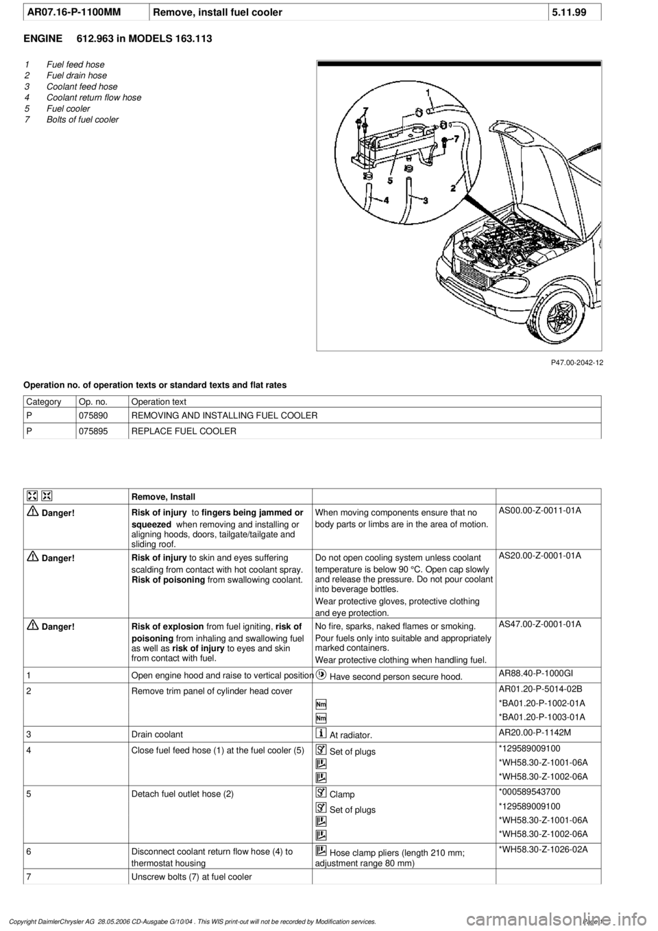
P47.00-2042-12
1
Fuel feed hose
2
Fuel drain hose
3
Coolant feed hose
4
Coolant return flow hose
5
Fuel cooler
7
Bolts of fuel cooler
Operation no. of operation texts or standard texts and flat rates
Category
Op. no.
Operation text
P
075890
REMOVING AND INSTALLING FUEL COOLER
P
075895
REPLACE FUEL COOLER
Remove, Install
Danger!
Risk of injury
to
fingers being jammed or
squeezed
when removing and installing or
aligning hoods, doors, tailgate/tailgate and
sliding roof.
When moving components ensure that no
body parts or limbs are in the area of motion.
AS00.00-Z-0011-01A
Danger!
Risk of injury
to skin and eyes suffering
scalding from contact with hot coolant spray.
Risk of poisoning
from swallowing coolant.
Do not open cooling system unless coolant
temperature is below 90 °C. Open cap slowly
and release the pressure. Do not pour coolant
into beverage bottles.
Wear protective gloves, protective clothing
and eye protection.
AS20.00-Z-0001-01A
Danger!
Risk of explosion
from fuel igniting,
risk of
poisoning
from inhaling and swallowing fuel
as well as
risk of injury
to eyes and skin
from contact with fuel.
No fire, sparks, naked flames or smoking.
Pour fuels only into suitable and appropriately
marked containers.
Wear protective clothing when handling fuel.
AS47.00-Z-0001-01A
1
Open engine hood and raise to vertical position
Have second person secure hood.
AR88.40-P-1000GI
2
Remove trim panel of cylinder head cover
AR01.20-P-5014-02B
*BA01.20-P-1002-01A
*BA01.20-P-1003-01A
3
Drain coolant
At radiator.
AR20.00-P-1142M
4
Close fuel feed hose (1) at the fuel cooler (5)
Set of plugs
*129589009100
*WH58.30-Z-1001-06A
*WH58.30-Z-1002-06A
5
Detach fuel outlet hose (2)
Clamp
*000589543700
Set of plugs
*129589009100
*WH58.30-Z-1001-06A
*WH58.30-Z-1002-06A
6
Disconnect coolant return flow hose (4) to
thermostat housing
Hose clamp pliers (length 210 mm;
adjustment range 80 mm)
*WH58.30-Z-1026-02A
7
Unscrew bolts (7) at fuel cooler
Copyright DaimlerChrysler AG 28.05.2006 CD-Ausgabe G/10/04 . This WIS print-out will not be recorde
d by Modification services.
Page 1
Page 2584 of 4133

8
Disconnect coolant feed hose (3) to fuel cooler
Raise fuel cooler.
Hose clamp pliers (length 210 mm;
adjustment range 80 mm)
*WH58.30-Z-1026-02A
9
Install in the reverse order
Danger!
Risk of accident
as vehicle may start off by
itself with the engine running.
Risk of injury
as working around the engine during start-up
or while running may result in contusions and
burns
Secure vehicle to prevent it from moving off
by itself.
Wear closed and tight-fitting work clothes.
Do not grasp hot or rotating parts.
AS00.00-Z-0005-01A
10
Pour in coolant
*BF20.00-P-1001-02E
Switch heater to maximum and warm up
engine at moderate revs. Top up coolant
constantly at coolant expansion reservoir.
Close coolant expansion reservoir once
coolant temperature is 60-70 °C.
Note on coolant level
Models 124, 129, 140, 168, 170, 202, 208,
210, 220, 463
AH20.00-P-1142-01A
11
Inspect cooling system for leaks
AR20.00-P-1010HA
12
Run engine and inspect fuel system for leaks
Crankcase ventilation, cylinder head cover
Number
Designation
Engine
612.963
BA01.20-P-1002-01A
Screw of trim panel of cylinder head cover
to cylinder head cover
NM
10
BA01.20-P-1003-01A
Screw attaching cover panel to charge air
distribution pipe
NM
10
Cooling system
Number
Designation
Engine
612.963
BF20.00-P-1001-02E
Cooling system
Total capacity
Liter
Y
11,0
Capacity of anticorrosion/
antifreeze agent down to -37 °C
Liter
Y
5,5
Capacity of anticorrosion/
antifreeze agent down to -45 °C
Liter
Y
6,25
Specifications for Service
Products
SheetBB00.40-P-0310-01A
SheetBB00.40-P-0325-02A
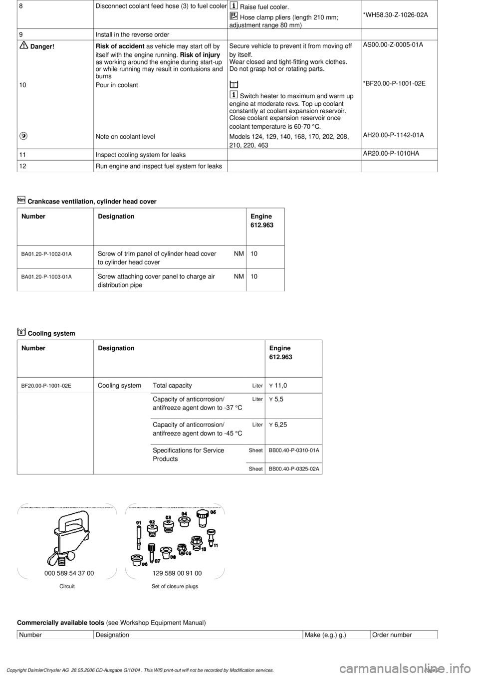
129 589 00 91 00
Set of closure plugs
Circuit
000 589 54 37 00
Commercially available tools
(see Workshop Equipment Manual)
Number
Designation
Make (e.g.) g.)
Order number
Copyright DaimlerChrysler AG 28.05.2006 CD-Ausgabe G/10/04 . This WIS print-out will not be recorde
d by Modification services.
Page 2
Page 2589 of 4133

AP47.20-P-0780BB
Replace fuel filter
2.3.99
ENGINE
611.960 in MODEL 202.133 /134 /193 /194
ENGINE
611.961 in MODEL 210.006 /007 /206 /606
ENGINE
612.961 in MODEL 210.016 /216 /616
ENGINE
612.963 in MODEL 163.113
ENGINE
613.961 in MODEL 210.026 /226
ENGINE
613.960 in MODEL 220.026 /126
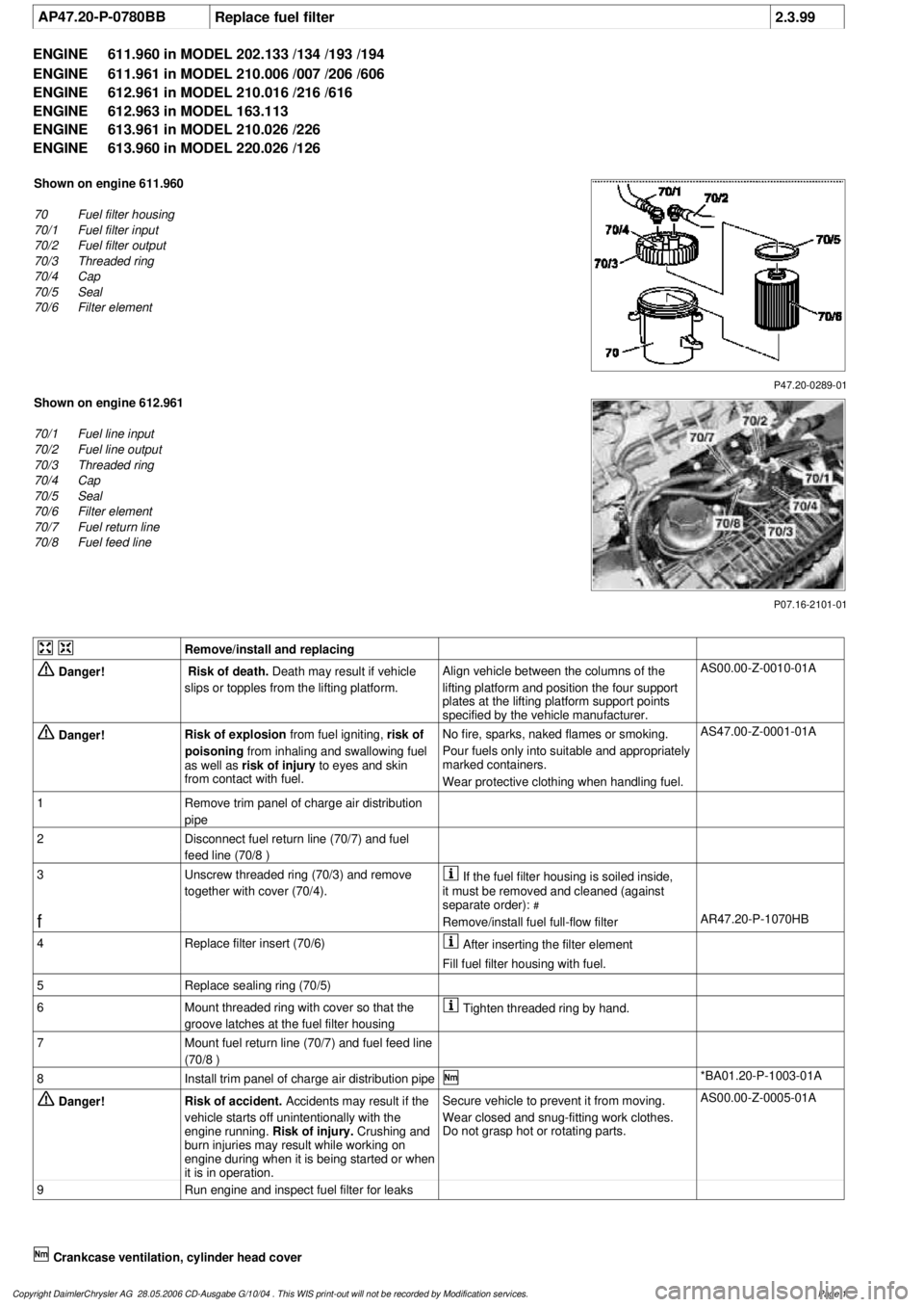
P47.20-0289-01
Shown on engine 611.960
70
Fuel filter housing
70/1
Fuel filter input
70/2
Fuel filter output
70/3
Threaded ring
70/4
Cap
70/5
Seal
70/6
Filter element
P07.16-2101-01
Shown on engine 612.961
70/1
Fuel line input
70/2
Fuel line output
70/3
Threaded ring
70/4
Cap
70/5
Seal
70/6
Filter element
70/7
Fuel return line
70/8
Fuel feed line
Remove/install and replacing
Danger!
Risk of death.
Death may result if vehicle
slips or topples from the lifting platform.
Align vehicle between the columns of the
lifting platform and position the four support
plates
at the lifting platform support points
specified by the vehicle manufacturer.
AS00.00-Z-0010-01A
Danger!
Risk of explosion
from fuel igniting,
risk of
poisoning
from inhaling and swallowing fuel
as well as
risk of injury
to eyes and skin
from contact with fuel.
No fire, sparks, naked flames or smoking.
Pour fuels only into suitable and appropriately
marked containers.
Wear protective clothing when handling fuel.
AS47.00-Z-0001-01A
1
Remove trim panel of charge air distribution
pipe
2
Disconnect fuel return line (70/7) and fuel
feed line (70/8 )
3
Unscrew threaded ring (70/3) and remove
together with cover (70/4).
If the fuel filter housing is soiled inside,
it must be removed and cleaned (against
separate order):
#
f
Remove/install fuel full-flow filter
AR47.20-P-1070HB
4
Replace filter insert (70/6)
After inserting the filter element
Fill fuel filter housing with fuel.
5
Replace sealing ring (70/5)
6
Mount threaded ring with cover so that the
groove latches at the fuel filter housing
Tighten threaded ring by hand.
7
Mount fuel return line (70/7) and fuel feed line
(70/8 )
8
Install trim panel of charge air distribution pipe
*BA01.20-P-1003-01A
Danger!
Risk of accident.
Accidents may result if the
vehicle starts off unintentionally with the
engine running.
Risk of injury.
Crushing and
burn injuries may result while working on
engine during when it is being started or when
it is in operation.
Secure vehicle to prevent it from moving.
Wear closed and snug-fitting work clothes.
Do not grasp hot or rotating parts.
AS00.00-Z-0005-01A
9
Run engine and inspect fuel filter for leaks
Crankcase ventilation, cylinder head cover
Copyright DaimlerChrysler AG 28.05.2006 CD-Ausgabe G/10/04 . This WIS print-out will not be recorde
d by Modification services.
Page 1
Page 2594 of 4133

2.1
Disconnect fuel lines (1,2) at main fuel filter
(70)
Engine 611
Collect escaping fuel.
Pay attention to use of locking arm. Refer
to:
#
Separate fuel lines from engine, reconnect
AR47.25-P-1000-01A
2.2
Disconnect fuel lines (1,2,3,4) at main fuel
filter (70)
Engine 612, 613
Collect escaping fuel.
Pay attention to use of locking arm. Refer
to:
#
Disconnect, connect fuel lines at engine.
AR47.25-P-1000-01A
3
Remove main fuel filter (70)
If the main fuel filter has been emptied, it
must be filled with fuel after being installed
before starting, the engine starts more easily.
*BA47.20-P-1001-02A
4
Install in the reverse order
Danger!
Risk of accident
due to automatic starting-off
when engine is running.
Injury hazard
due to
crimped connection and combustion when
meshing during starting procedure or when
engine is running
Secure vehicle to prevent it from moving off
by itself.
Wear closed and close-fitting work clothes.
Do not grasp hot or rotating parts.
AS00.00-Z-0005-01A
5
Run engine and inspect fuel system for leaks
Crankcase ventilation, cylinder head cover
Number
Designation
Engine
611.960/
961/962
Engine
612.961/
962/967
Engine
612.963
Engine
613.960/
961
BA01.20-P-1003-01A
Screw attaching cover panel to charge air
distribution pipe
Nm
10101010
Fuel filter
Number
Designation
Engine
611.960/
961
Engine
611.962
Engine
612.961/
963
Engine
613.960/
961
BA47.20-P-1001-02A
Bolt of fuel filter to charge air distribution pipe
Nm
14141414
Copyright DaimlerChrysler AG 28.05.2006 CD-Ausgabe G/10/04 . This WIS print-out will not be recorde
d by Modification services.
Page 2
Page 2596 of 4133

AR47.10-P-7000GI
Remove/install fuel level sensor
21.2.01
MODEL
163.113 with ENGINE 612.963
MODEL
163.128 with ENGINE 628.963
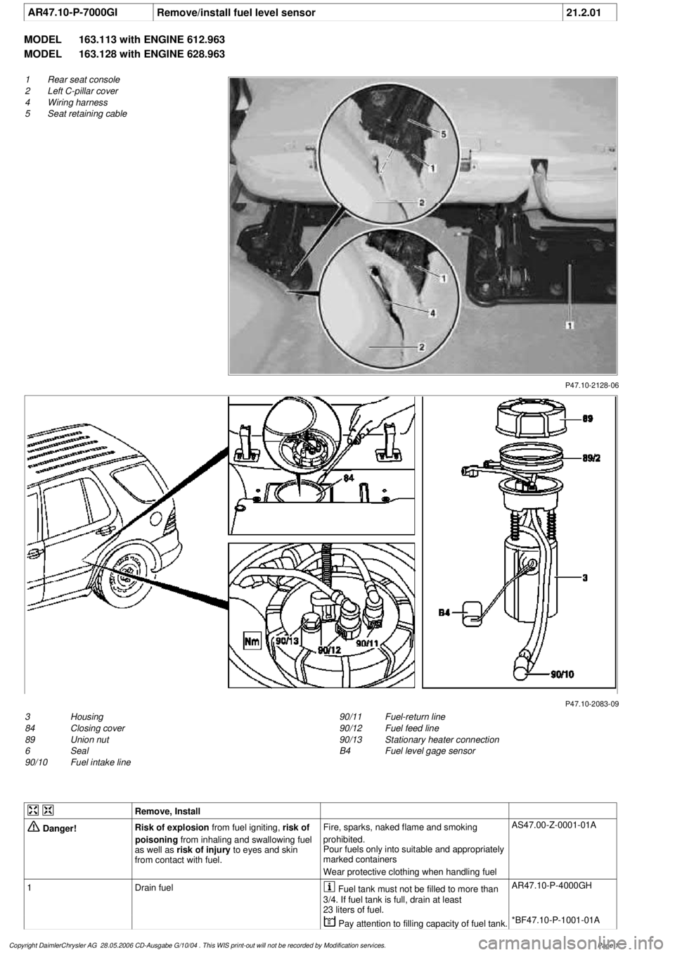
P47.10-2128-06
1
Rear seat console
2
Left C-pillar cover
4
Wiring harness
5
Seat retaining cable
P47.10-2083-09
3
Housing
84
Closing cover
89
Union nut
6
Seal
90/10
Fuel intake line
90/11
Fuel-return line
90/12
Fuel feed line
90/13
Stationary heater connection
B4
Fuel level gage sensor
Remove, Install
Danger!
Risk of explosion
from fuel igniting,
risk of
poisoning
from inhaling and swallowing fuel
as well as
risk of injury
to eyes and skin
from contact with fuel.
Fire, sparks, naked flame and smoking
prohibited.
Pour fuels only into suitable and appropriately
marked containers
Wear protective clothing when handling fuel
AS47.00-Z-0001-01A
1
Drain fuel
Fuel tank must not be filled to more than
3/4. If fuel tank is full, drain at least
23 liters of fuel.
AR47.10-P-4000GH
Pay attention to filling capacity of fuel tank.
*BF47.10-P-1001-01A
Copyright DaimlerChrysler AG 28.05.2006 CD-Ausgabe G/10/04 . This WIS print-out will not be recorde
d by Modification services.
Page 1
Page 2597 of 4133

2
Remove covers at seat frame of 60% bench
seat
As of VIN A145273, X708319.
AR91.12-P-1100GH
Only remove the covers which are
identified in the document with A, D and E.
3
Fold 60% bench seat forward into footwell
As of VIN A145273, X708319. See
operator's manual.
4
Pull floor covering below rear seat mounting
bracket (1) of 60% seat forward
Ensure that the floor covering is not torn
when pulled forward.
As of VIN A145273, X708319.
5
Pull floor covering below front corner of trim
panel of C-pillar (2) forward
Ensure that the floor covering is not torn
when pulled forward.
As of VIN A145273, X708319.
6
Cut into floor covering directly behind seat
retaining cable (5)
Ensure that the wiring harness (4) is not
damaged when cutting into floor covering.
As of VIN A145273, X708319. broken line
marks cut-in.
7
Turn back floor covering to gain access to
cap (84)
Do not kink floor covering.
8
Remove cap (84)
Cap (84) is sealed in with body sealer.
Heat with hot air blower to make it easier to
remove.
Installation:
Replace cap and install with
new sealing compound.
9
Detach fuel feed line (90/12) and fuel return
line (90/11) and, if fitted, the fuel line at
connection (90/13)
Do not kink the fuel lines.
If no stationary heater is fitted to vehicle,
do not remove connection (90/13) otherwise
housing will be damaged.
*163589003700
10
Remove nut (89)
*163589010700
*BA47.20-P-1006-01B
11
Remove housing (3)
Fuel lever sensor and housing are a
single part and cannot be removed separately.
Installation:
Re-install nut (89) together
with seal (89/2).
Apply a thin film of oil to seal.
12
Install in the reverse order
Fuel pump
Number
Designation
Engine 612Engine 628
BA47.20-P-1006-01B
Union nut for fuel tank sensor on fuel
tank
Nm
6565
Fuel tank
Number
Designation
Models
163.113/
136/154/
172 up to
31.08.01
Model
163.113/
136/154/
172 as of
01.09.01
Model
163.157/
175
Model
163.128
BF47.10-P-1001-01A
Fuel tank capacity
Total capacity
Liter
728383
Reserve capacity
Liter
101212
Copyright DaimlerChrysler AG 28.05.2006 CD-Ausgabe G/10/04 . This WIS print-out will not be recorde
d by Modification services.
Page 2