1997 MERCEDES-BENZ ML350 change wheel
[x] Cancel search: change wheelPage 3382 of 4133

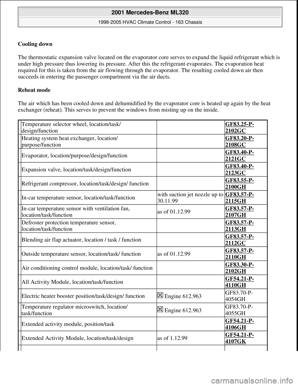
Cooling down
The thermostatic expansion valve located on the evaporator core serves to expand the liquid refrigerant which is
under high pressure thus lowering its pressure. After this the refrigerant evaporates. The evaporation heat
required for this is taken from the air flowing through the evaporator. The resulting cooled down air then
succeeds in entering the passenger compartment via the air ducts.
Reheat mode
The air which has been cooled down and dehumidified by the evaporator core is heated up again by the heat
exchanger (reheat). This serves to prevent the windows from misting up on the inside.
Temperature selector wheel, location/task/
design/function GF83.25-P-
2102GC
Heating system heat exchanger, location/
purpose/function GF83.20-P-
2108GC
Evaporator, location/purpose/design/function GF83.40-P-
2121GC
Expansion valve, location/task/design/function GF83.40-P-
2123GC
Refrigerant compressor, location/task/design/ function GF83.55-P-
2100GH
In-car temperature sensor, location/task/functionwith suction jet nozzle up to
30.11.99GF83.57-P-
2115GH
In-car temperature sensor with ventilation fan,
location/task/functionas of 01.12.99GF83.57-P-
2107GH
Defroster protection temperature sensor,
location/task/function GF83.57-P-
2113GH
Blending air flap actuator, location / task / function GF83.57-P-
2112GC
Outside temperature sensor, location/task/ functionas of 01.12.99GF83.57-P-
2110GH
Air conditioning control module, location/task/ function GF83.30-P-
2102GH
All Activity Module, location/task/function GF54.21-P-
4110GH
Electric heater booster position/task/design/ function Engine 612.963GF83.70-P-
4054GH
Temperature regulator microswitch, location/
task/function Engine 612.963GF83.70-P-
4055GH
Extended activity module, position/task GF54.21-P-
4106GH
Extended Activity Module, location/task/designas of 1.12.99GF54.21-P-
4107GK
2001 Mercedes-Benz ML320
1998-2005 HVAC Climate Control - 163 Chassis
me
Saturday, October 02, 2010 3:23:17 PMPage 138 © 2006 Mitchell Repair Information Company, LLC.
Page 3383 of 4133

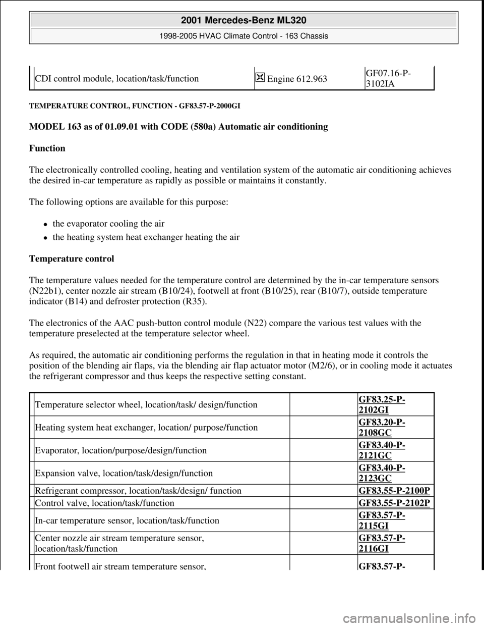
TEMPERATURE CONTROL, FUNCTION - GF83.57-P-2000GI
MODEL 163 as of 01.09.01 with CODE (580a) Automatic air conditioning
Function
The electronically controlled cooling, heating and ventilation system of the automatic air conditioning achieves
the desired in-car temperature as rapidly as possible or maintains it constantly.
The following options are available for this purpose:
the evaporator cooling the air
the heating system heat exchanger heating the air
Temperature control
The temperature values needed for the temperature control are determined by the in-car temperature sensors
(N22b1), center nozzle air stream (B10/24), footwell at front (B10/25), rear (B10/7), outside temperature
indicator (B14) and defroster protection (R35).
The electronics of the AAC push-button control module (N22) compare the various test values with the
temperature preselected at the temperature selector wheel.
As required, the automatic air conditioning performs the regulation in that in heating mode it controls the
position of the blending air flaps, via the blending air flap actuator motor (M2/6), or in cooling mode it actuates
the refrigerant compressor and thus keeps the respective setting constant.
CDI control module, location/task/function Engine 612.963GF07.16-P-
3102IA
Temperature selector wheel, location/task/ design/function GF83.25-P-
2102GI
Heating system heat exchanger, location/ purpose/function GF83.20-P-
2108GC
Evaporator, location/purpose/design/function GF83.40-P-
2121GC
Expansion valve, location/task/design/function GF83.40-P-
2123GC
Refrigerant compressor, location/task/design/ function GF83.55-P-2100P
Control valve, location/task/function GF83.55-P-2102P
In-car temperature sensor, location/task/function GF83.57-P-
2115GI
Center nozzle air stream temperature sensor,
location/task/function GF83.57-P-
2116GI
Front footwell air stream temperature sensor, GF83.57-P-
2001 Mercedes-Benz ML320
1998-2005 HVAC Climate Control - 163 Chassis
me
Saturday, October 02, 2010 3:23:17 PMPage 139 © 2006 Mitchell Repair Information Company, LLC.
Page 3387 of 4133

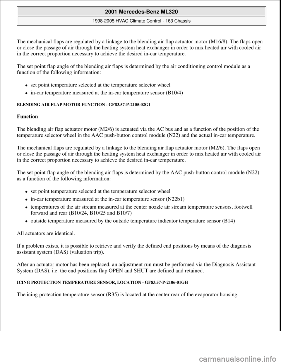
The mechanical flaps are regulated by a linkage to the blending air flap actuator motor (M16/8). The flaps open
or close the passage of air through the heating system heat exchanger in order to mix heated air with cooled air
in the correct proportion necessary to achieve the desired in-car temperature.
The set point flap angle of the blending air flaps is determined by the air conditioning control module as a
function of the following information:
set point temperature selected at the temperature selector wheel
in-car temperature measured at the in-car temperature sensor (B10/4)
BLENDING AIR FLAP MOTOR FUNCTION - GF83.57-P-2105-02GI
Function
The blending air flap actuator motor (M2/6) is actuated via the AC bus and as a function of the position of the
temperature selector wheel in the AAC push-button control module (N22) and the actual in-car temperature.
The mechanical flaps are regulated by a linkage to the blending air flap actuator motor (M2/6). The flaps open
or close the passage of air through the heating system heat exchanger in order to mix heated air with cooled air
in the correct proportion necessary to achieve the desired in-car temperature.
The set point flap angle of the blending air flaps is determined by the AAC push-button control module (N22)
as a function of the following information:
set point temperature selected at the temperature selector wheel
in-car temperature measured at the in-car temperature sensor (N22b1)
temperatures of the air stream measured at the center nozzle air stream temperature sensors, footwell
forward and rear (B10/24, B10/25 and B10/7)
outside temperature measured by the outside temperature indicator temperature sensor (B14)
All actuators are identical.
If a problem exists, it is possible to retrieve and verify the defined end positions by means of the diagnosis
assistant system (DAS) (valuation trip).
After an actuator motor has been replaced, an adjustment run must be performed via the Diagnosis Assistant
System (DAS), i.e. the end positions flap OPEN and SHUT are defined and retained.
ICING PROTECTION TEMPERATURE SENSOR, LOCATION - GF83.57-P-2106-01GH
The icing protection temperature sensor (R35) is located at the center rear of the evaporator housing.
2001 Mercedes-Benz ML320
1998-2005 HVAC Climate Control - 163 Chassis
me
Saturday, October 02, 2010 3:23:17 PMPage 143 © 2006 Mitchell Repair Information Company, LLC.
Page 3479 of 4133

BT27.00-Z-9999AZ
Technical modifications: Passenger cars: Automatic transmission
30.4.97
MODEL all
Vacuum unit for modulating pressure modified
TRANSMISSION 722.3 /5 as of 15.8.92
BT27.10-P-0001-01A
Secondary pump dispensed with
TRANSMISSION 722.5## ## as of 3652931
BT27.10-P-0002-01A
Control pressure cable with vacuum actuators
standardized
TRANSMISSION 722.3 /4 /5 as of 1.7.93
BT27.10-P-0003-01A
Sump volume modified
TRANSMISSION 722.7## ## as of 0054011
as of 29.7.99
BT27.10-P-0004-01A
Additional shim between deep-groove ball
bearing and output flange
TRANSMISSION 722 ...
BT27.10-P-0005-01A
Oil pan and overflow tube modified
TRANSMISSION 722.901
BT27.10-P-0006-01W
Retaining lug added to electrohydraulic
control module
TRANSMISSION 722.6## # as of 0026195
BT27.19-P-0001-01A
Caps for solenoid valve, new
TRANSMISSION 722.6 as of 1.8.97
BT27.19-P-0003-01A
Oil drain plug on torque converter deleted
TRANSMISSION 722.6## /6## ## as of
1772285 as of 22.9.99
BT27.20-P-0001-01A
Small intermediate plate modified
TRANSMISSION 722.5## ## as of 3987361
as of 15.3.94
BT27.35-P-0001-01A
Installation of a pressure feed valve
TRANSMISSION 722.6## # as of 0027083
BT27.35-P-0002-01A
Primary pump non-return valve dispensed with
TRANSMISSION 722.5## ## as of 3652931
BT27.35-P-0003-01A
Strainer for modulating pressure and shift
pressure control solenoid valve, new
TRANSMISSION 722.6## ## as of 0538312
BT27.35-P-0004-01A
Strainer in inlet to converter lock-up control
solenoid valve, newTRANSMISSION 722.6## ## as of 0485895
BT27.35-P-0005-01A
Feed B1 enlarged
TRANSMISSION 722.5 as of 15.8.91
BT27.40-P-0001-01A
Fluid reservoir deleted
TRANSMISSION 722.7## ## as of 0111673
as of 11.9.00
BT27.40-P-0002-01A
Magnet in oil pan, new part
TRANSMISSION 722.6## ## as of 2871384
as of 17.4.01, 722.7## ## as of 0153700 as
of 9.7.01
BT27.40-P-0003-01A
Piston B1 modified
TRANSMISSION 722.5## ## as of 3746852
as of 15.6.92, 722.3## ## as of 3969172
BT27.50-P-0002-01A
Plain bearing of input shaft changed to an anti-
friction bearing
TRANSMISSION 722 ...
BT27.50-P-0002-02A
One-way valve dispensed with
TRANSMISSION 722.5## ## as of 3652931
BT27.50-P-0007-01A
Outer multiple-disc carrier B1 modified
TRANSMISSION 722.6## # as of 0005900
BT27.50-P-0008-01A
Peak-to-valley height on piston B2 modified
TRANSMISSION 722.6## # as of 0023104
BT27.50-P-0009-01A
Piston B2 changed
TRANSMISSION 722.6## ## as of 0552036
as of 1.8.97
BT27.50-P-0010-01A
Friction bearing in sun wheel of rear planet
gear set converted to anti-friction bearing
TRANSMISSION 722 ...
BT27.50-P-0011-01A
Conversion from 18° to 23° gearing in front
and rear planetary gear system
TRANSMISSION 722 ...
BT27.50-P-0012-01A
Multi-disks for B1, K1 and K3 changed
TRANSMISSION 722.6## ## as of 3947440
as of 2.9.02
BT27.50-P-0013-01A
Thickness of friction and steel disks K3
changed
TRANSMISSION 722.6
BT27.51-P-0001-01A
Thickness of steel plates of B1, K1 and K2
modified
TRANSMISSION 722.6## ## as of 1596205
as of 15.6.99
BT27.51-P-0002-01A
Additional dished washer in multi-plate set K2
TRANSMISSION 722.6## ## as of 1596205
as of 15.6.99
BT27.51-P-0003-01A
Center shift modified
TRANSMISSION 722.6
BT27.60-P-0001-01A
Deletion shift lock cable ignition lock to
transmission
TRANSMISSION 722.7 in MODEL
WDB168.### ## as of 548031 as of 10.1.01
BT27.60-P-0001-02A
Selector lever soldered
TRANSMISSION 722.6 as of 1.5.96
BT27.60-P-0002-01A
Deletion of lever for shift lock cable ignition
lock at transmission
TRANSMISSION 722.700 ## as of 0129631
as of 24.1.01, 722.701 ## as of 0132072 as
of 8.2.01
BT27.60-P-0003-01A
Copyright DaimlerChrysler AG 28.05.2006 CD-Ausgabe G/10/04 . This WIS print-out will not be recorde
d by Modification services.
Page 1
Page 3966 of 4133

3
Features
This telephone system is fully integrated with your Mercedes-Benz audio system and steering wheel switches
*
. You can
scroll through the first 99 entries in your phone book and access the entire phone number memory; place, receive, and
terminate calls; change volume; and view call status (such as Ready, Dialing, Incoming Call, Call Active, No Service, Redial,
etc.). Because exact phone features are dependent on the particular audio system installed in your vehicle, detailed oper-
ation is covered in your audio system manual. Please refer to it.
Notes:
• In order for your Mercedes-Benz volume controls to work in conjunction with your Motorola phone (to change ringer
volume or adjust call volume), the vehicle must have either the engine running or the ignition key turned clockwise
to the last position before starting the engine.
• Your phone includes many new features that take additional time to initialize, resulting in increased power up/down
time. Please wait until the phone is completely powered up before using any feature from both the radio and phone
controls.
Finding Information on Phone Features
Your new Mercedes-Benz telephone operates in two modes:
•
Vehicular Mode
—when the phone is inserted and snapped into the privacy cradle in the vehicle
•
Portable Mode
—when the phone is operating as a stand alone device (NOT inserted and snapped into the privacy
cradle in the vehicle)
Most features of your new Mercedes-Benz telephone are available in both modes.
This guide contains basic information on using your phone in Vehicular Mode to place and receive calls.
* Not available on all models.
Page 3994 of 4133

AP40.10-P-4050GH
Remove/install wheels, rotate if necessary
15.7.97
MODEL
163
1-5
Tightening sequence
P40.10-0004-01
P40.00-0208-01
Remove
Danger!
Lethal injuries
are possible if vehicle slips off
of lifting platform
Align vehicle between the columns of the
lifting platform and position the four support
plates
at the lifting platform support points
specified by the vehicle manufacturer.
AS00.00-Z-0010-01A
Comply with notes on tires / rims
AH40.10-P-9411-01A
1
Raise vehicle.
AS00.00-Z-0010-01A
2
Unscrew wheel bolts, remove wheels
3
Check wheel bolts
The round contact shoulders on the lug
bolts must be free of oil and grease.
Replace bolts that have a damaged thread,
worn dacromet coating at radius seat or
corroded radius seat.
4
Check tires for damage and wear - measure
depth of tread
AP40.10-P-4051Z
5
Check disk wheels
D
check for contamination,
D
check that spherical caps are free of oil
and grease,
D
check centering, spherical caps and rim
flanges for damage,
D
check corrosion of lay-on surface
6
Check front wheel hub, brake disk bowl at
attachment face for contamination and
corrosion
Clean corroded surfaces with a wire brush or
an emery cloth.
Install
7
Change wheels around if necessary retaining
the same running direction
This excludes vehicles with mixed tires at
the front and rear axle.
Between
5,000 and 10,000 km according to wear.
8
Fit wheels, tighten wheel bolts
Observe tightening sequence "1-5".
*BA40.10-P-1001-01A
*126589040900
9
Lower vehicle, correct tire inflation pressure
(including spare wheel)
In the case of loss of tire pressure,
determine cause and replace tire if necessary.
On versions with spare tire attached to
underside of vehicle, check tire inflation
pressure of spare tire before lowering the
vehicle.
c
Deletion of spare tire with model 163.174
with TIREFIT
AH40.10-P-0001-01A
Wheels
Number
Designation
Models
163.113/128/
136/154/157/
172/175
Model
163.174
Copyright DaimlerChrysler AG 06.07.2006 CD-Ausgabe G/10/04 . This WIS print-out will not be recorde
d by Modification services.
Page 1