1997 MERCEDES-BENZ ML350 alarm
[x] Cancel search: alarmPage 1135 of 4133
331 Index
Oil
Adding 221
Consumption 218
Dipstick 218
Oil dipstick 221
Viscosity 312
One-touch gearshifting 120
Canceling gear range limit 120
Downshifting 120
Upshifting 120
Opening
Doors from the inside 90
Fuel filler flap 214
Fuel filler flap manually 263
Glove box 164
Hood 217
Liftgate 89, 91
Liftgate from inside 91
Liftgate from outside 91
Rear quarter windows 146
Side windows 145Sliding/pop-up roof* 148, 265
Sliding/pop-up roof* in an
emergency 265
Storage compartment in front of
armrest 166
Storage compartment under passenger
seat 165
Windows 145
Opening and closing
Side windows 144
Operating
Garage door opener 185
Integrated remote control 185
Radio transmitters 211
Vehicle outside the USA and
Canada 13
Operating safety 17
Operator’s Manual 10
Ornamental moldings 236
Outside temperature indicator 118
Overdue service 233
Overhead control panel 29P
Paintwork 235
Panic alarm 75
Panic button on remote control 75
Parking and locking 53
Parking brake 47, 53
Engaging 53
Releasing 47
Parking lamps
Replacing bulbs 266, 267, 269
Replacing the bulbs 269
Switching on 107
Parktronic* 153, 313
Cleaning system sensor 237
Monitoring reach 154
Sensor cover 237
Switching off 156
Switching on 156
Warning indicators 155
Page 1142 of 4133
338 IndexTele Aid* 171
Emergency calls 173
Information 177
Initiating an emergency call
manually 175
Remote door unlock 179
Roadside assistance 175
Stolen vehicle tracking services 180
System self-check 172
Upgrade signals 178
Telematics* 315
Telephone* 170
Temperature
Grades of tires 309
Tires 228
Third row seats* 102
Folding down single seat 102
Installing single seat 104
Removing single seat 104
Storing single seat 103
Tie-down rings (Cargo
compartment) 158Tightening torque 315
Tightening torque (Wheel bolts) 277
Tilt
Head restraint 37, 39
Time
Setting hours 118
Setting minutes 118
Tire inflation pressure
Checking 216, 227
Tire speed rating 198, 315
Tire traction 197
Tires 295, 308
Direction of rotation 227
Driving instructions 196
Retreads 226
Rims and tires 295
Rotating 228
Service life 227
Temperature 228
Temperature grades 309
Tread depth 230
Wear pattern 228
Winter 230Tools 257
Vehicle jack 258
Vehicles with CD-changer* 258
Wheel bolt wrench 258
Tow-away alarm 29, 84
Arming 84
Disarming 84
Disarming for transport 84
Towing
Trailer 206
Towing a trailer 209
Automatic transmission 124
Towing eyes
Front 285
Rear 285
Towing the vehicle 283
Stranded vehicle 286
Tracking services
For stolen vehicle 180
Page 1184 of 4133
Connect ground cable.
4 - Code radio.
5 - Set time at instrument cluster
6.1 - Activate steering angle sensor.
7.1 - Synchronize tilt/slide sunroof.
8.1 - Synchronize lamella (thin plate) sliding roof.
9.1 - Synchronize power windows.
Torque Specification; Nut Of Ground Cable To Body NOTE: After opening the vehicle wait for at least 4 minutes before disconnecting
the battery otherwise the alarm will be triggered.
NOTE: Model 163: Tighten the nut (5) of the ground line (1) to the specified
torque. Perform work described below only when quiescent current
retention unit was not connected. Model Series 163 see Torque
Specification; Nut Of Ground Cable To Body.
NOTE: MB (models 163).
Hi-Line, premium with Bose (model 163).
NOTE: If necessary set time at stationary heater timer.
NOTE: Model 163 with Code 414.
Open tilt/slide sunroof and hold down switch. Sliding/pop-up roof
mechanism moves to end position, pulls back 1/4 turn and stops.
NOTE: Open tilt/slide sunroof and hold down switch. Sliding/pop-up roof
mechanism moves to end position, pulls back 1/4 turn and stops.
NOTE: Model 163 as of VIN A289565, X754620.
Press power windows switch up to the 1st pressure point and, after
reaching the upper end position of the window, keep pressed for further 5
seconds.
NumberDesignationModel Series 163
BA54.10--P-1001--01ANut of ground cable to bodyNM18
2001 Mercedes-Benz ML320
1998-03 AUTOMATIC TRANSMISSIONS Complete Transmissions - ML 320 - 722.662
me
Saturday, October 02, 2010 3:15:25 PMPage 15 © 2006 Mitchell Repair Information Company, LLC.
Page 1553 of 4133
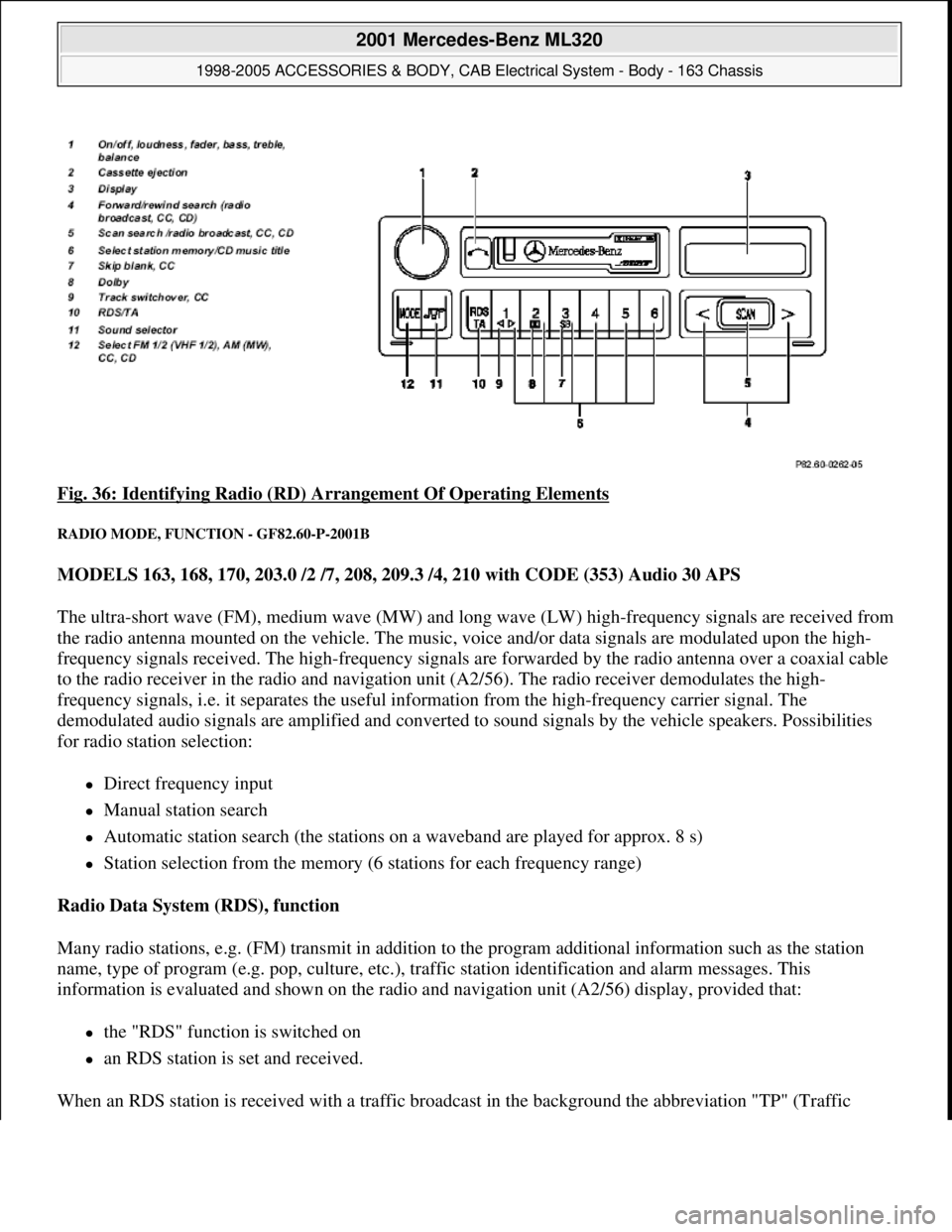
Fig. 36: Identifying Radio (RD) Arrangement Of Operating Elements
RADIO MODE, FUNCTION - GF82.60-P-2001B
MODELS 163, 168, 170, 203.0 /2 /7, 208, 209.3 /4, 210 with CODE (353) Audio 30 APS
The ultra-short wave (FM), medium wave (MW) and long wave (LW) high-frequency signals are received from
the radio antenna mounted on the vehicle. The music, voice and/or data signals are modulated upon the high-
frequency signals received. The high-frequency signals are forwarded by the radio antenna over a coaxial cable
to the radio receiver in the radio and navigation unit (A2/56). The radio receiver demodulates the high-
frequency signals, i.e. it separates the useful information from the high-frequency carrier signal. The
demodulated audio signals are amplified and converted to sound signals by the vehicle speakers. Possibilities
for radio station selection:
Direct frequency input
Manual station search
Automatic station search (the stations on a waveband are played for approx. 8 s)
Station selection from the memory (6 stations for each frequency range)
Radio Data System (RDS), function
Many radio stations, e.g. (FM) transmit in addition to the program additional information such as the station
name, type of program (e.g. pop, culture, etc.), traffic station identification and alarm messages. This
information is evaluated and shown on the radio and navigation unit (A2/56) display, provided that:
the "RDS" function is switched on
an RDS station is set and received.
When an RDS station is received with a traffic broadcast in the background the abbreviation "TP" (Traffic
2001 Mercedes-Benz ML320
1998-2005 ACCESSORIES & BODY, CAB Electrical System - Body - 163 Chassis
me
Saturday, October 02, 2010 3:30:05 PMPage 58 © 2006 Mitchell Repair Information Company, LLC.
Page 1554 of 4133
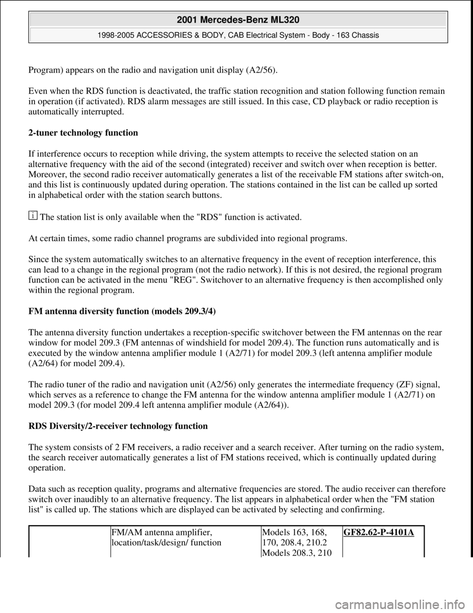
Program) appears on the radio and navigation unit display (A2/56).
Even when the RDS function is deactivated, the traffic station recognition and station following function remain
in operation (if activated). RDS alarm messages are still issued. In this case, CD playback or radio reception is
automatically interrupted.
2-tuner technology function
If interference occurs to reception while driving, the system attempts to receive the selected station on an
alternative frequency with the aid of the second (integrated) receiver and switch over when reception is better.
Moreover, the second radio receiver automatically generates a list of the receivable FM stations after switch-on,
and this list is continuously updated during operation. The stations contained in the list can be called up sorted
in alphabetical order with the station search buttons.
The station list is only available when the "RDS" function is activated.
At certain times, some radio channel programs are subdivided into regional programs.
Since the system automatically switches to an alternative frequency in the event of reception interference, this
can lead to a change in the regional program (not the radio network). If this is not desired, the regional program
function can be activated in the menu "REG". Switchover to an alternative frequency is then accomplished only
within the regional program.
FM antenna diversity function (models 209.3/4)
The antenna diversity function undertakes a reception-specific switchover between the FM antennas on the rear
window for model 209.3 (FM antennas of windshield for model 209.4). The function runs automatically and is
executed by the window antenna amplifier module 1 (A2/71) for model 209.3 (left antenna amplifier module
(A2/64) for model 209.4).
The radio tuner of the radio and navigation unit (A2/56) only generates the intermediate frequency (ZF) signal,
which serves as a reference to change the FM antenna for the window antenna amplifier module 1 (A2/71) on
model 209.3 (for model 209.4 left antenna amplifier module (A2/64)).
RDS Diversity/2-receiver technology function
The system consists of 2 FM receivers, a radio receiver and a search receiver. After turning on the radio system,
the search receiver automatically generates a list of FM stations received, which is continually updated during
operation.
Data such as reception quality, programs and alternative frequencies are stored. The audio receiver can therefore
switch over inaudibly to an alternative frequency. The list appears in alphabetical order when the "FM station
list" is called up. The stations which are displayed can be activated by selecting and confirming.
FM/AM antenna amplifier,
location/task/design/ functionModels 163, 168,
170, 208.4, 210.2
Models 208.3, 210 GF82.62-P-4101A
2001 Mercedes-Benz ML320
1998-2005 ACCESSORIES & BODY, CAB Electrical System - Body - 163 Chassis
me
Saturday, October 02, 2010 3:30:05 PMPage 59 © 2006 Mitchell Repair Information Company, LLC.
Page 1566 of 4133
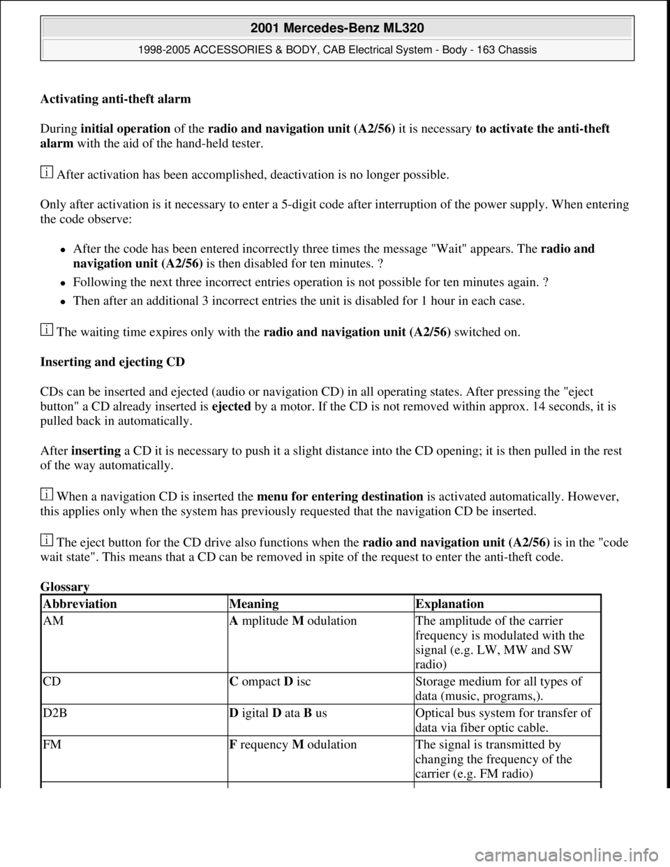
Activating anti-theft alarm
During initial operation of the radio and navigation unit (A2/56) it is necessary to activate the anti-theft
alarm with the aid of the hand-held tester.
After activation has been accomplished, deactivation is no longer possible.
Only after activation is it necessary to enter a 5-digit code after interruption of the power supply. When entering
the code observe:
After the code has been entered incorrectly three times the message "Wait" appears. The radio and
navigation unit (A2/56) is then disabled for ten minutes. ?
Following the next three incorrect entries operation is not possible for ten minutes again. ?
Then after an additional 3 incorrect entries the unit is disabled for 1 hour in each case.
The waiting time expires only with the radio and navigation unit (A2/56) switched on.
Inserting and ejecting CD
CDs can be inserted and ejected (audio or navigation CD) in all operating states. After pressing the "eject
button" a CD already inserted is ejected by a motor. If the CD is not removed within approx. 14 seconds, it is
pulled back in automatically.
After inserting a CD it is necessary to push it a slight distance into the CD opening; it is then pulled in the rest
of the way automatically.
When a navigation CD is inserted the menu for entering destination is activated automatically. However,
this applies only when the system has previously requested that the navigation CD be inserted.
The eject button for the CD drive also functions when the radio and navigation unit (A2/56)is in the "code
wait state". This means that a CD can be removed in spite of the request to enter the anti-theft code.
Glossary
AbbreviationMeaningExplanation
AMA mplitude M odulationThe amplitude of the carrier
frequency is modulated with the
signal (e.g. LW, MW and SW
radio)
CDC ompact D iscStorage medium for all types of
data (music, programs,).
D2BD igital D ata B usOptical bus system for transfer of
data via fiber optic cable.
FMF requency M odulationThe signal is transmitted by
changing the frequency of the
carrier (e.g. FM radio)
2001 Mercedes-Benz ML320
1998-2005 ACCESSORIES & BODY, CAB Electrical System - Body - 163 Chassis
me
Saturday, October 02, 2010 3:30:05 PMPage 71 © 2006 Mitchell Repair Information Company, LLC.
Page 2141 of 4133
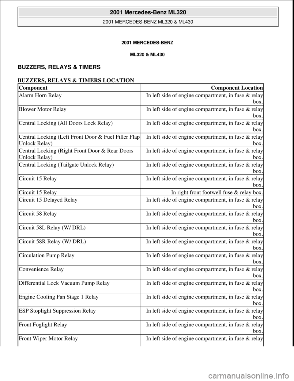
2001 MERCEDES-BENZ
ML320 & ML430
BUZZERS, RELAYS & TIMERS
BUZZERS, RELAYS & TIMERS LOCATION
ComponentComponent Location
Alarm Horn RelayIn left side of engine compartment, in fuse & relay
box.
Blower Motor RelayIn left side of engine compartment, in fuse & relay
box.
Central Locking (All Doors Lock Relay)In left side of engine compartment, in fuse & relay
box.
Central Locking (Left Front Door & Fuel Filler Flap
Unlock Relay)In left side of engine compartment, in fuse & relay
box.
Central Locking (Right Front Door & Rear Doors
Unlock Relay)In left side of engine compartment, in fuse & relay
box.
Central Locking (Tailgate Unlock Relay)In left side of engine compartment, in fuse & relay
box.
Circuit 15 RelayIn left side of engine compartment, in fuse & relay
box.
Circuit 15 RelayIn right front footwell fuse & relay box.
Circuit 15 Delayed RelayIn left side of engine compartment, in fuse & relay
box.
Circuit 58 RelayIn left side of engine compartment, in fuse & relay
box.
Circuit 58L Relay (W/ DRL)In left side of engine compartment, in fuse & relay
box.
Circuit 58R Relay (W/ DRL)In left side of engine compartment, in fuse & relay
box.
Circulation Pump RelayIn left side of engine compartment, in fuse & relay
box.
Convenience RelayIn left side of engine compartment, in fuse & relay
box.
Differential Lock Vacuum Pump RelayIn left side of engine compartment, in fuse & relay
box.
Engine Cooling Fan Stage 1 RelayIn left side of engine compartment, in fuse & relay
box.
ESP Stoplight Suppression RelayIn left side of engine compartment, in fuse & relay
box.
Front Foglight RelayIn left side of engine compartment, in fuse & relay
box.
Front Wiper Motor RelayIn left side of engine compartment, in fuse & relay
2001 Mercedes-Benz ML320
2001 MERCEDES-BENZ ML320 & ML430
2001 Mercedes-Benz ML320
2001 MERCEDES-BENZ ML320 & ML430
me
Saturday, October 02, 2010 3:21:17 PMPage 1 © 2006 Mitchell Repair Information Company, LLC.
me
Saturday, October 02, 2010 3:21:20 PMPage 1 © 2006 Mitchell Repair Information Company, LLC.
Page 2146 of 4133
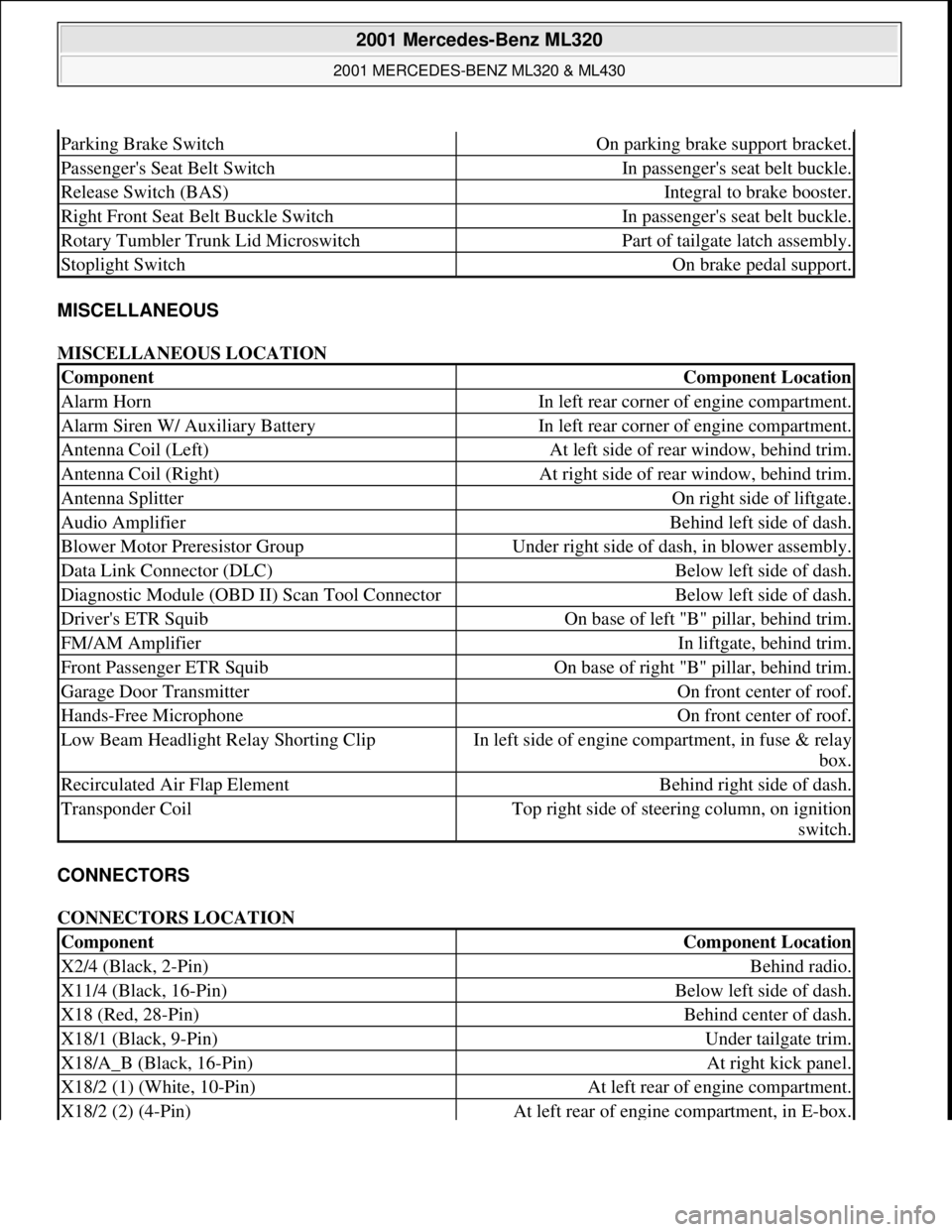
MISCELLANEOUS
MISCELLANEOUS LOCATION
CONNECTORS
CONNECTORS LOCATION
Parking Brake SwitchOn parking brake support bracket.
Passenger's Seat Belt SwitchIn passenger's seat belt buckle.
Release Switch (BAS)Integral to brake booster.
Right Front Seat Belt Buckle SwitchIn passenger's seat belt buckle.
Rotary Tumbler Trunk Lid MicroswitchPart of tailgate latch assembly.
Stoplight SwitchOn brake pedal support.
ComponentComponent Location
Alarm HornIn left rear corner of engine compartment.
Alarm Siren W/ Auxiliary BatteryIn left rear corner of engine compartment.
Antenna Coil (Left)At left side of rear window, behind trim.
Antenna Coil (Right)At right side of rear window, behind trim.
Antenna SplitterOn right side of liftgate.
Audio AmplifierBehind left side of dash.
Blower Motor Preresistor GroupUnder right side of dash, in blower assembly.
Data Link Connector (DLC)Below left side of dash.
Diagnostic Module (OBD II) Scan Tool ConnectorBelow left side of dash.
Driver's ETR SquibOn base of left "B" pillar, behind trim.
FM/AM AmplifierIn liftgate, behind trim.
Front Passenger ETR SquibOn base of right "B" pillar, behind trim.
Garage Door TransmitterOn front center of roof.
Hands-Free MicrophoneOn front center of roof.
Low Beam Headlight Relay Shorting ClipIn left side of engine compartment, in fuse & relay
box.
Recirculated Air Flap ElementBehind right side of dash.
Transponder CoilTop right side of steering column, on ignition
switch.
ComponentComponent Location
X2/4 (Black, 2-Pin)Behind radio.
X11/4 (Black, 16-Pin)Below left side of dash.
X18 (Red, 28-Pin)Behind center of dash.
X18/1 (Black, 9-Pin)Under tailgate trim.
X18/A_B (Black, 16-Pin)At right kick panel.
X18/2 (1) (White, 10-Pin)At left rear of engine compartment.
X18/2 (2) (4-Pin)At left rear of engine compartment, in E-box.
2001 Mercedes-Benz ML320
2001 MERCEDES-BENZ ML320 & ML430
me
Saturday, October 02, 2010 3:21:17 PMPage 6 © 2006 Mitchell Repair Information Company, LLC.