1997 MERCEDES-BENZ ML350 brake fluid
[x] Cancel search: brake fluidPage 1370 of 4133
Operation
The term power transmission refers to the transmission of propulsion power and engine torques. Via the
mechanical/hydraulic connection between the engine, torque converter and the downstream automatic
transmission the engine torques are transmitted to the driving wheels and are converted in the transmission via
several planetary gear sets.
Power is transferred in the torque converter via the driven impeller by diverting hydraulic fluid to the turbine
wheel, which is connected to the input shaft. See Fig. 117
.
When the torque converter lockup clutch is engaged, power is transmitted via this mechanical connection. Via
the gear wheels of the individual planetary gear sets the torques coming from the converter are passed on to the
output shaft with the aid of freewheels, multi-disk clutches and brakes, depending on the ratio and shift element
operated.
A reduction of the output speed in the low gears provides lower vehicle speeds with high tractive forces and
drive torques at the drive wheels.
Power Flow In 1st Gear, Function
See POWER FLOW IN 1ST GEAR, FUNCTION
.
Power Flow In 2nd Gear, Function
See POWER FLOW IN 2ND GEAR FUNCTION
.
Power Flow In 3rd Gear, Function
See POWER FLOW IN 3RD GEAR FUNCTION
.
Power Flow In 4th Gear, Function
See POWER FLOW IN 4TH GEAR FUNCTION
.
Power Flow In 5th Gear, Function
See POWER FLOW IN 5TH GEAR FUNCTION
.
Power Flow In Reverse, Function
See POWER FLOW IN REVERSE, FUNCTION
.
Function Of Torque Converter Lock-Up Clutch Control
See FUNCTION OF TORQUE CONVERTER LOCKUP CLUTCH CONTROL
.
Power Flow In 1st Gear, Function
2001 Mercedes-Benz ML320
1998-03 AUTOMATIC TRANSMISSIONS Complete Transmissions - ML 320 - 722.662
me
Saturday, October 02, 2010 3:15:28 PMPage 201 © 2006 Mitchell Repair Information Company, LLC.
Page 2144 of 4133
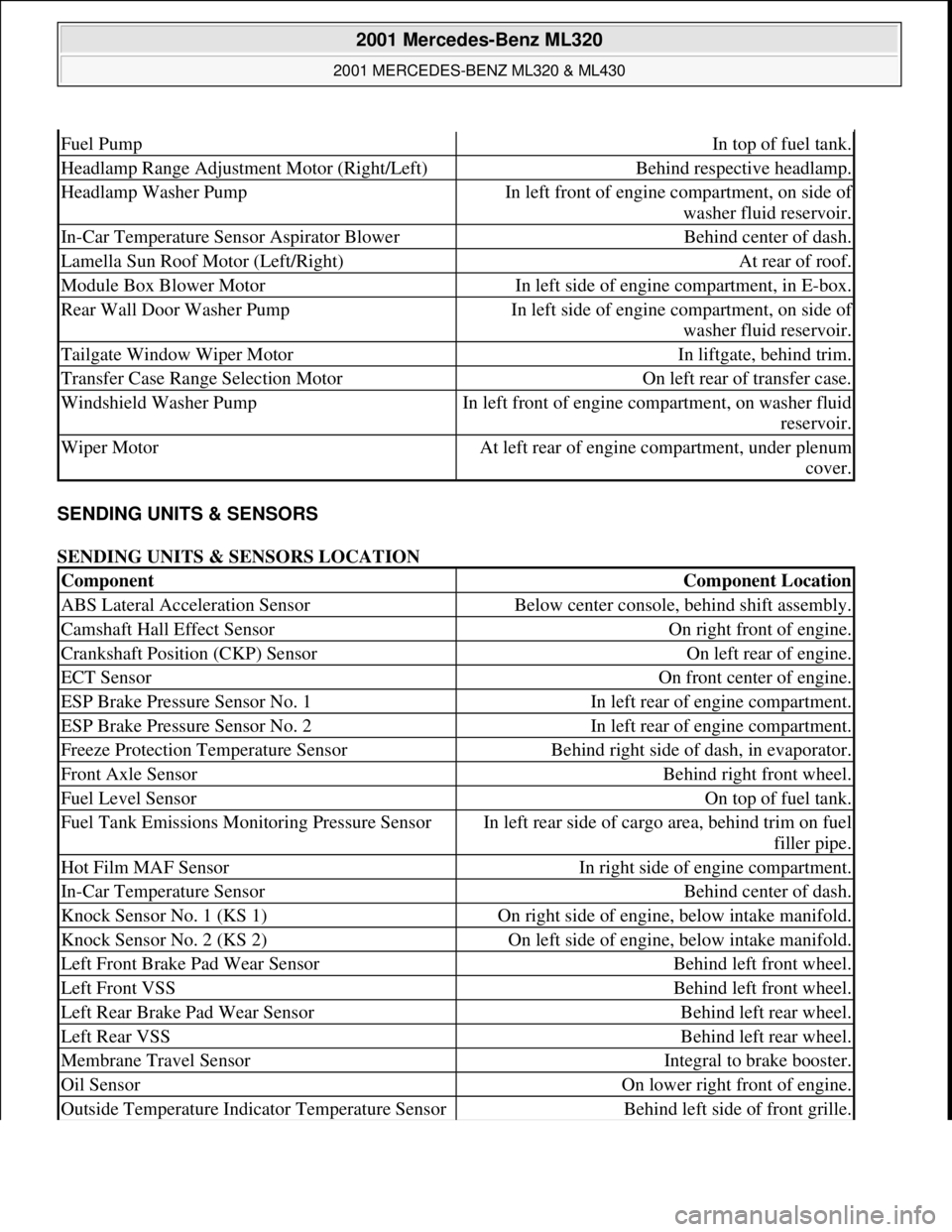
SENDING UNITS & SENSORS
SENDING UNITS & SENSORS LOCATION
Fuel PumpIn top of fuel tank.
Headlamp Range Adjustment Motor (Right/Left)Behind respective headlamp.
Headlamp Washer PumpIn left front of engine compartment, on side of
washer fluid reservoir.
In-Car Temperature Sensor Aspirator BlowerBehind center of dash.
Lamella Sun Roof Motor (Left/Right)At rear of roof.
Module Box Blower MotorIn left side of engine compartment, in E-box.
Rear Wall Door Washer PumpIn left side of engine compartment, on side of
washer fluid reservoir.
Tailgate Window Wiper MotorIn liftgate, behind trim.
Transfer Case Range Selection MotorOn left rear of transfer case.
Windshield Washer PumpIn left front of engine compartment, on washer fluid
reservoir.
Wiper MotorAt left rear of engine compartment, under plenum
cover.
ComponentComponent Location
ABS Lateral Acceleration SensorBelow center console, behind shift assembly.
Camshaft Hall Effect SensorOn right front of engine.
Crankshaft Position (CKP) SensorOn left rear of engine.
ECT SensorOn front center of engine.
ESP Brake Pressure Sensor No. 1In left rear of engine compartment.
ESP Brake Pressure Sensor No. 2In left rear of engine compartment.
Freeze Protection Temperature SensorBehind right side of dash, in evaporator.
Front Axle SensorBehind right front wheel.
Fuel Level SensorOn top of fuel tank.
Fuel Tank Emissions Monitoring Pressure SensorIn left rear side of cargo area, behind trim on fuel
filler pipe.
Hot Film MAF SensorIn right side of engine compartment.
In-Car Temperature SensorBehind center of dash.
Knock Sensor No. 1 (KS 1)On right side of engine, below intake manifold.
Knock Sensor No. 2 (KS 2)On left side of engine, below intake manifold.
Left Front Brake Pad Wear SensorBehind left front wheel.
Left Front VSSBehind left front wheel.
Left Rear Brake Pad Wear SensorBehind left rear wheel.
Left Rear VSSBehind left rear wheel.
Membrane Travel SensorIntegral to brake booster.
Oil SensorOn lower right front of engine.
Outside Temperature Indicator Temperature SensorBehind left side of front grille.
2001 Mercedes-Benz ML320
2001 MERCEDES-BENZ ML320 & ML430
me
Saturday, October 02, 2010 3:21:17 PMPage 4 © 2006 Mitchell Repair Information Company, LLC.
Page 2145 of 4133
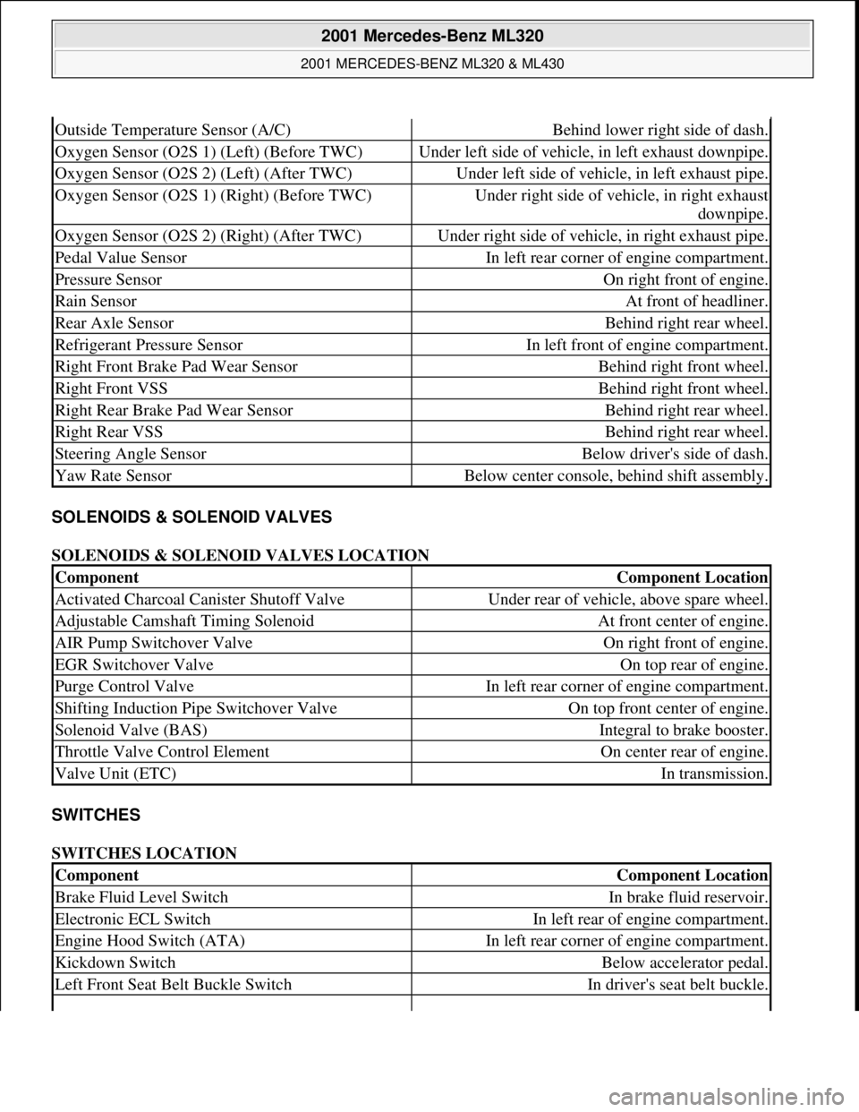
SOLENOIDS & SOLENOID VALVES
SOLENOIDS & SOLENOID VALVES LOCATION
SWITCHES
SWITCHES LOCATION
Outside Temperature Sensor (A/C)Behind lower right side of dash.
Oxygen Sensor (O2S 1) (Left) (Before TWC)Under left side of vehicle, in left exhaust downpipe.
Oxygen Sensor (O2S 2) (Left) (After TWC)Under left side of vehicle, in left exhaust pipe.
Oxygen Sensor (O2S 1) (Right) (Before TWC)Under right side of vehicle, in right exhaust
downpipe.
Oxygen Sensor (O2S 2) (Right) (After TWC)Under right side of vehicle, in right exhaust pipe.
Pedal Value SensorIn left rear corner of engine compartment.
Pressure SensorOn right front of engine.
Rain SensorAt front of headliner.
Rear Axle SensorBehind right rear wheel.
Refrigerant Pressure SensorIn left front of engine compartment.
Right Front Brake Pad Wear SensorBehind right front wheel.
Right Front VSSBehind right front wheel.
Right Rear Brake Pad Wear SensorBehind right rear wheel.
Right Rear VSSBehind right rear wheel.
Steering Angle SensorBelow driver's side of dash.
Yaw Rate SensorBelow center console, behind shift assembly.
ComponentComponent Location
Activated Charcoal Canister Shutoff ValveUnder rear of vehicle, above spare wheel.
Adjustable Camshaft Timing SolenoidAt front center of engine.
AIR Pump Switchover ValveOn right front of engine.
EGR Switchover ValveOn top rear of engine.
Purge Control ValveIn left rear corner of engine compartment.
Shifting Induction Pipe Switchover ValveOn top front center of engine.
Solenoid Valve (BAS)Integral to brake booster.
Throttle Valve Control ElementOn center rear of engine.
Valve Unit (ETC)In transmission.
ComponentComponent Location
Brake Fluid Level SwitchIn brake fluid reservoir.
Electronic ECL SwitchIn left rear of engine compartment.
Engine Hood Switch (ATA)In left rear corner of engine compartment.
Kickdown SwitchBelow accelerator pedal.
Left Front Seat Belt Buckle SwitchIn driver's seat belt buckle.
2001 Mercedes-Benz ML320
2001 MERCEDES-BENZ ML320 & ML430
me
Saturday, October 02, 2010 3:21:17 PMPage 5 © 2006 Mitchell Repair Information Company, LLC.
Page 2214 of 4133
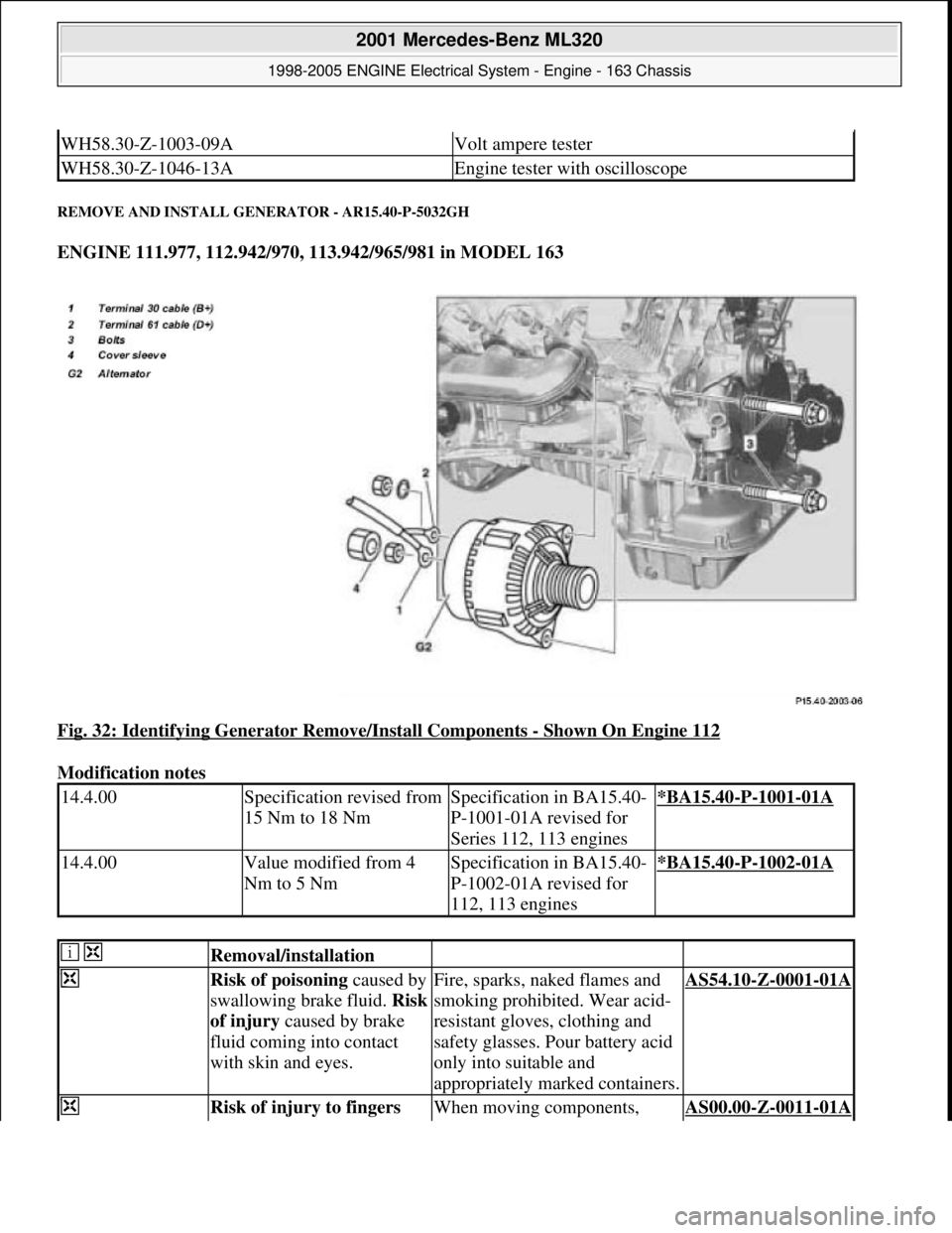
REMOVE AND INSTALL GENERATOR - AR15.40-P-5032GH
ENGINE 111.977, 112.942/970, 113.942/965/981 in MODEL 163
Fig. 32: Identifying Generator Remove/Install Components
- Shown On Engine 112
Modification notes
WH58.30-Z-1003-09AVolt ampere tester
WH58.30-Z-1046-13AEngine tester with oscilloscope
14.4.00Specification revised from
15 Nm to 18 NmSpecification in BA15.40-
P-1001-01A revised for
Series 112, 113 engines*BA15.40-P-1001-01A
14.4.00Value modified from 4
Nm to 5 NmSpecification in BA15.40-
P-1002-01A revised for
112, 113 engines*BA15.40-P-1002-01A
Removal/installation
Risk of poisoning caused by
swallowing brake fluid. Risk
of injury caused by brake
fluid coming into contact
with skin and eyes.Fire, sparks, naked flames and
smoking prohibited. Wear acid-
resistant gloves, clothing and
safety glasses. Pour battery acid
only into suitable and
appropriately marked containers.AS54.10-Z-0001-01A
Risk of injury to fingers When moving components, AS00.00-Z-0011-01A
2001 Mercedes-Benz ML320
1998-2005 ENGINE Electrical System - Engine - 163 Chassis
me
Saturday, October 02, 2010 3:18:54 PMPage 60 © 2006 Mitchell Repair Information Company, LLC.
Page 2509 of 4133
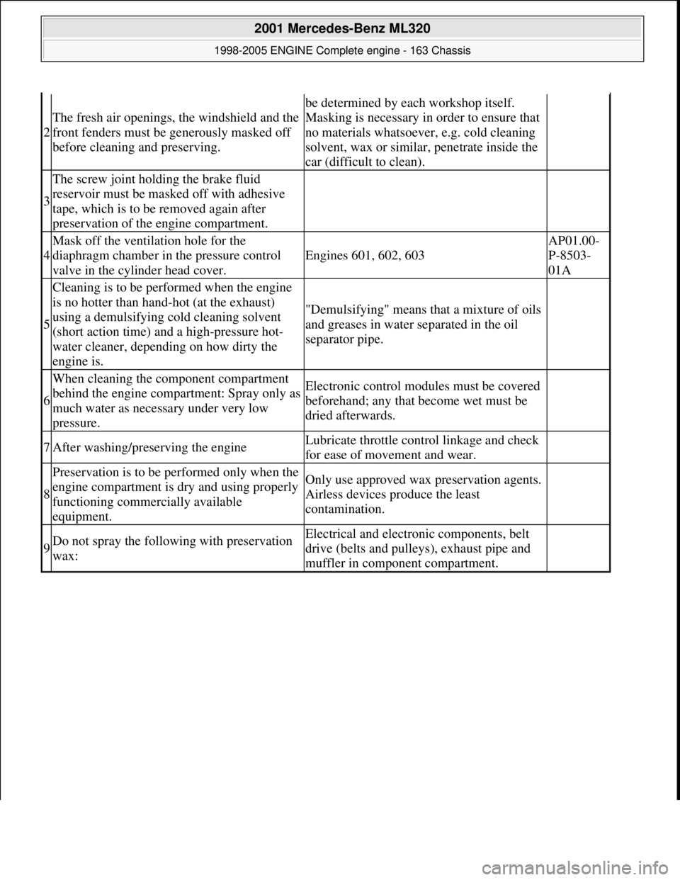
2
The fresh air openings, the windshield and the
front fenders must be generously masked off
before cleaning and preserving.
be determined by each workshop itself.
Masking is necessary in order to ensure that
no materials whatsoever, e.g. cold cleaning
solvent, wax or similar, penetrate inside the
car (difficult to clean).
3
The screw joint holding the brake fluid
reservoir must be masked off with adhesive
tape, which is to be removed again after
preservation of the engine compartment.
4
Mask off the ventilation hole for the
diaphragm chamber in the pressure control
valve in the cylinder head cover.
Engines 601, 602, 603
AP01.00-
P-8503-
01A
5
Cleaning is to be performed when the engine
is no hotter than hand-hot (at the exhaust)
using a demulsifying cold cleaning solvent
(short action time) and a high-pressure hot-
water cleaner, depending on how dirty the
engine is.
"Demulsifying" means that a mixture of oils
and greases in water separated in the oil
separator pipe.
6
When cleaning the component compartment
behind the engine compartment: Spray only as
much water as necessary under very low
pressure.Electronic control modul es must be covered
beforehand; any that become wet must be
dried afterwards.
7After washing/preserving the engineLubricate throttle cont rol linkage and check
for ease of movement and wear.
8
Preservation is to be performed only when the
engine compartment is dry and using properly
functioning commercially available
equipment.Only use approved wax preservation agents.
Airless devices produce the least
contamination.
9Do not spray the follow ing with preservation
wax:Electrical and electroni c components, belt
drive (belts and pulleys), exhaust pipe and
muffler in component compartment.
2001 Mercedes-Benz ML320
1998-2005 ENGINE Complete engine - 163 Chassis
me
Saturday, October 02, 2010 3:17:58 PMPage 153 © 2006 Mitchell Repair Information Company, LLC.
Page 2523 of 4133
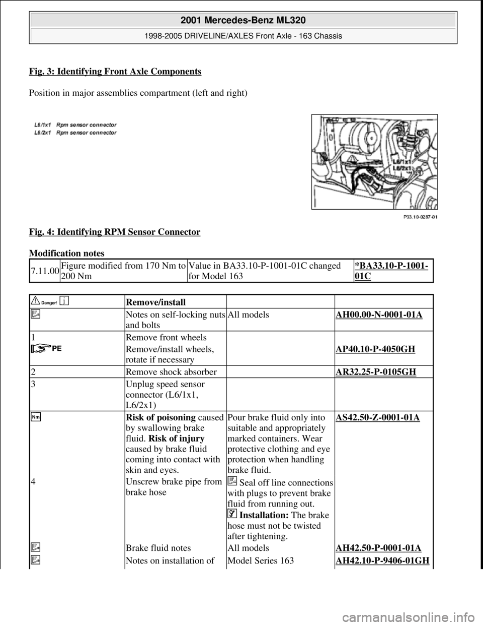
Fig. 3: Identifying Front Axle Components
Position in major assemblies compartment (left and right)
Fig. 4: Identifying RPM Sensor Connector
Modification notes
7.11.00Figure modified from 170 Nm to
200 NmValue in BA33.10-P-1001-01C changed
for Model 163*BA33.10-P-1001-
01C
Remove/install
Notes on self-locking nuts
and boltsAll modelsAH00.00-N-0001-01A
1Remove front wheels
Remove/install wheels,
rotate if necessaryAP40.10-P-4050GH
2Remove shock absorber AR32.25-P-0105GH
3Unplug speed sensor
connector (L6/1x1,
L6/2x1)
Risk of poisoning caused
by swallowing brake
fluid. Risk of injury
caused by brake fluid
coming into contact with
skin and eyes.Pour brake fluid only into
suitable and appropriately
marked containers. Wear
protective clothing and eye
protection when handling
brake fluid.AS42.50-Z-0001-01A
4Unscrew brake pipe from
brake hoseSeal off line connections
with plugs to prevent brake
fluid from running out.
Installation: The brake
hose must not be twisted
after tightening.
Brake fluid notesAll modelsAH42.50-P-0001-01A
Notes on installation of Model Series 163AH42.10-P-9406-01GH
2001 Mercedes-Benz ML320
1998-2005 DRIVELINE/AXLES Front Axle - 163 Chassis
me
Saturday, October 02, 2010 3:38:21 PMPage 4 © 2006 Mitchell Repair Information Company, LLC.
Page 2524 of 4133
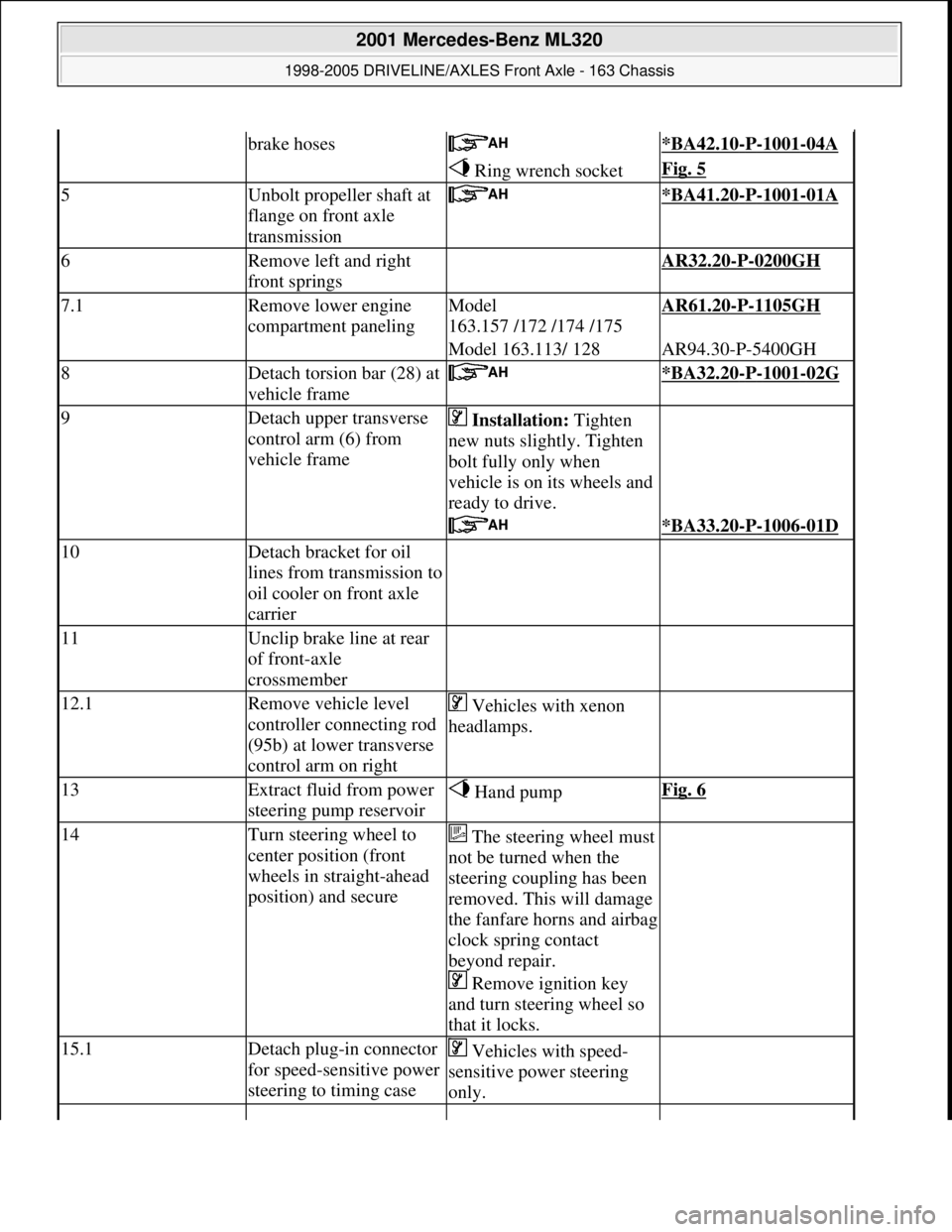
brake hoses *BA42.10-P-1001-04A
Ring wrench socketFig. 5
5Unbolt propeller shaft at
flange on front axle
transmission *BA41.20-P-1001-01A
6Remove left and right
front springs AR32.20-P-0200GH
7.1Remove lower engine
compartment panelingModel
163.157 /172 /174 /175AR61.20-P-1105GH
Model 163.113/ 128AR94.30-P-5400GH
8Detach torsion bar (28) at
vehicle frame *BA32.20-P-1001-02G
9Detach upper transverse
control arm (6) from
vehicle frame Installation: Tighten
new nuts slightly. Tighten
bolt fully only when
vehicle is on its wheels and
ready to drive.
*BA33.20-P-1006-01D
10Detach bracket for oil
lines from transmission to
oil cooler on front axle
carrier
11Unclip brake line at rear
of front-axle
crossmember
12.1Remove vehicle level
controller connecting rod
(95b) at lower transverse
control arm on right Vehicles with xenon
headlamps.
13Extract fluid from power
steering pump reservoir Hand pumpFig. 6
14Turn steering wheel to
center position (front
wheels in straight-ahead
position) and secureThe steering wheel must
not be turned when the
steering coupling has been
removed. This will damage
the fanfare horns and airbag
clock spring contact
beyond repair.
Remove ignition key
and turn steering wheel so
that it locks.
15.1Detach plug-in connector
for speed-sensitive power
steering to timing case Vehicles with speed-
sensitive power steering
only.
2001 Mercedes-Benz ML320
1998-2005 DRIVELINE/AXLES Front Axle - 163 Chassis
me
Saturday, October 02, 2010 3:38:21 PMPage 5 © 2006 Mitchell Repair Information Company, LLC.
Page 2532 of 4133
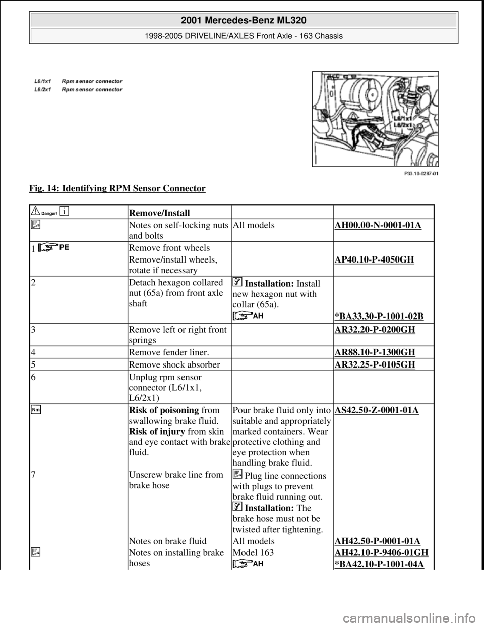
Fig. 14: Identifying RPM Sensor Connector
Remove/Install
Notes on self-locking nuts
and boltsAll modelsAH00.00-N-0001-01A
1 Remove front wheels
Remove/install wheels,
rotate if necessaryAP40.10-P-4050GH
2Detach hexagon collared
nut (65a) from front axle
shaft Installation: Install
new hexagon nut with
collar (65a).
*BA33.30-P-1001-02B
3Remove left or right front
springs AR32.20-P-0200GH
4Remove fender liner. AR88.10-P-1300GH
5Remove shock absorber AR32.25-P-0105GH
6Unplug rpm sensor
connector (L6/1x1,
L6/2x1)
Risk of poisoning from
swallowing brake fluid.
Risk of injury from skin
and eye contact with brake
fluid.Pour brake fluid only into
suitable and appropriately
marked containers. Wear
protective clothing and
eye protection when
handling brake fluid.AS42.50-Z-0001-01A
7Unscrew brake line from
brake hose Plug line connections
with plugs to prevent
brake fluid running out.
Installation: The
brake hose must not be
twisted after tightening.
Notes on brake fluidAll modelsAH42.50-P-0001-01A
Notes on installing brake
hosesModel 163AH42.10-P-9406-01GH
*BA42.10-P-1001-04A
2001 Mercedes-Benz ML320
1998-2005 DRIVELINE/AXLES Front Axle - 163 Chassis
me
Saturday, October 02, 2010 3:38:22 PMPage 13 © 2006 Mitchell Repair Information Company, LLC.