1997 MERCEDES-BENZ ML350 height adjustment
[x] Cancel search: height adjustmentPage 1140 of 4133
336 IndexSide windows 144
Automatic closing 145
Automatic opening 145
Cleaning 237
Closing 145
Closing fully (Express-close) 145
Opening 145
Opening and closing 144
Opening fully (Express-open) 145
Rear quarter window 146
Stopping 145
Synchronizing power windows 146
Simultaneous wiping and washing
Rear window wiper/washer 51
Windshield wipers 50
Single wipe 50
Sliding/pop-up roof* 148
Closing 148, 265
Opening 148, 265
Synchronizing 149
Snow chains 231
Spare fuses 287
Spare parts service 290Spare wheel 259
Mounting 274
Removing 259
Speed
Saving current 151
Speed settings
Cruise control 152
Speedometer 25
Speedometer display
Additional indicators 256
Split rear bench seat 99
SRS 66, 314
Indicator lamp 255
Standing lamps 107
Replacing bulbs 266, 267
Standing water
Driving instructions 200
StArt
Display messages 256
Starting difficulties 47
Starting position 33
Starting the engine 46Steep terrain
Driving 202
Steering column
Height adjustment 39
Length adjustment 39
Steering lock 23, 33
Positions 33
Steering wheel
Adjusting 39
Adjustment 39
Cleaning 238
Stolen vehicle
Tracking services 180
Stop watch 189
Stopping
Windows 145
Storage compartments
Glove box 164
Under front passenger seat* 164
Storing (Memory function*)
Positions into memory 106
Stranded vehicle 286
Page 1819 of 4133
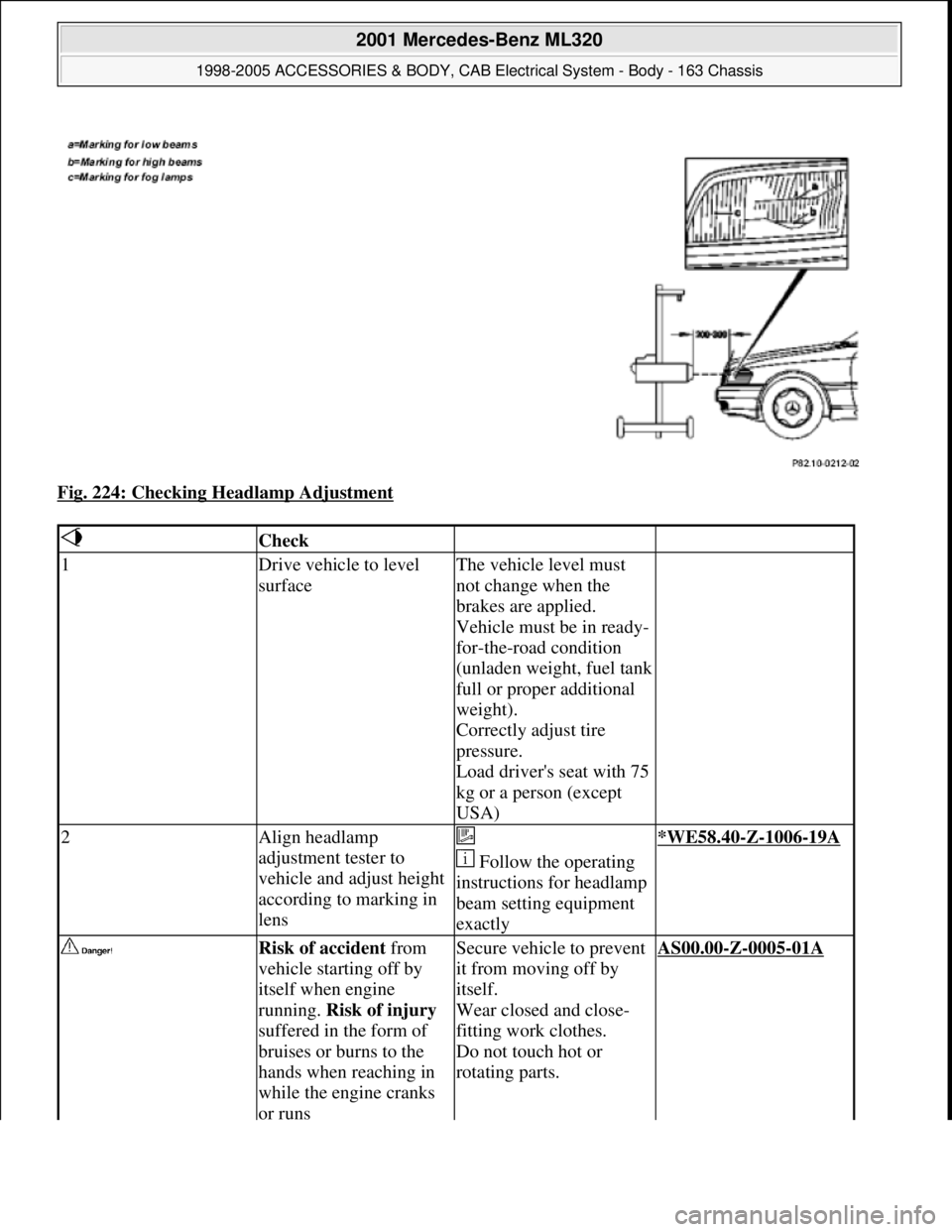
Fig. 224: Checking Headlamp Adjustment
Check
1Drive vehicle to level
surfaceThe vehicle level must
not change when the
brakes are applied.
Vehicle must be in ready-
for-the-road condition
(unladen weight, fuel tank
full or proper additional
weight).
Correctly adjust tire
pressure.
Load driver's seat with 75
kg or a person (except
USA)
2Align headlamp
adjustment tester to
vehicle and adjust height
according to marking in
lens
Follow the operating
instructions for headlamp
beam setting equipment
exactly*WE58.40-Z-1006-19A
Risk of accident from
vehicle starting off by
itself when engine
running. Risk of injury
suffered in the form of
bruises or burns to the
hands when reaching in
while the engine cranks
or runsSecure vehicle to prevent
it from moving off by
itself.
Wear closed and close-
fitting work clothes.
Do not touch hot or
rotating parts.AS00.00-Z-0005-01A
2001 Mercedes-Benz ML320
1998-2005 ACCESSORIES & BODY, CAB Electrical System - Body - 163 Chassis
me
Saturday, October 02, 2010 3:30:10 PMPage 324 © 2006 Mitchell Repair Information Company, LLC.
Page 1887 of 4133
material (8)
18Plug remaining antenna
cable of FM modulator
(9) into radio
19Install radio (A2)
Remove/install radio AR82.60-P-7502EA
20Retrofit video monitor (2)
and wiring harness of
video monitor (C) With glass version of
electric sliding/tilting
roof, code 414a.AZ82.60-P-0004-02A
Except glass version
of electric sliding/ tilting
roof, code 414a.AZ82.60-P-0004-02B
21Secure upper right B-
pillar paneling Ensure that the lugs of
the seat belt height
adjustment are located
correctly in the recess
clearance of the paneling.
22Install right front handle
23Install right sun visor
Remove/install sun visor AR68.60-P-5480GH
24Install right front A-pillar
cover
Remove/install paneling
on A-pillar AR68.30-P-4050GH
25Re-secure upper area of
rubber door seal
26Route wiring harness of
video/DVD player (B),
additional interface
module (4) and wiring
harness of video monitor
(C) later Up to VIN A289564,
X754619.AZ82.60-P-0004-03A
As of VIN A289565,
X754620.AZ82.60-P-0004-03B
27Retrofit auxiliary
interface module (4) in
center console Up to VIN A289564,
X754619.AZ82.60-P-0004-04A
As of VIN A289565,
X754620.AZ82.60-P-0004-04B
28Install center console
insulating mat
29Install center console
Remove/install center
console AR68.20-P-2000GH
2001 Mercedes-Benz ML320
1998-2005 ACCESSORIES & BODY, CAB Electrical System - Body - 163 Chassis
me
Saturday, October 02, 2010 3:30:12 PMPage 392 © 2006 Mitchell Repair Information Company, LLC.
Page 1970 of 4133
AP82.10-P-8260GH
Check and correct headlamp adjustment
2.7.97
MODEL
163
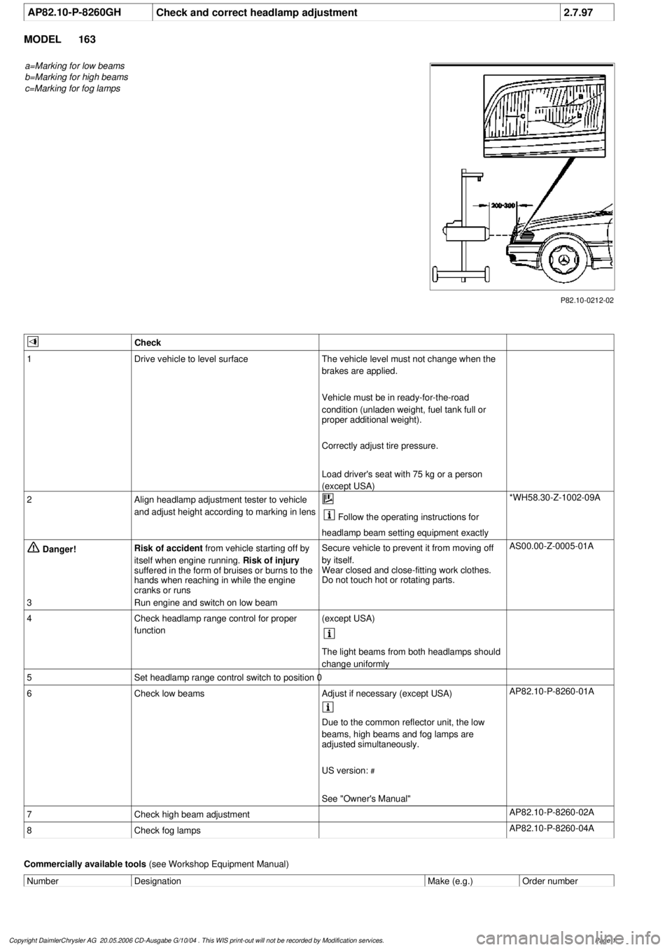
a=Marking for low beams
b=Marking for high beams
c=Marking for fog lamps
P82.10-0212-02
Check
1
Drive vehicle to level surface
The vehicle level must not change when the
brakes are applied.
Vehicle must be in ready-for-the-road
condition (unladen weight, fuel tank full or
proper additional weight).
Correctly adjust tire pressure.
Load driver's seat with 75 kg or a person
(except USA)
2
Align headlamp adjustment tester to vehicle
and adjust height according to marking in lens
Follow the operating instructions for
headlamp beam setting equipment exactly
*WH58.30-Z-1002-09A
Danger!
Risk of accident
from vehicle starting off by
itself when engine running.
Risk of injury
suffered in the form of bruises or burns to the
hands when reaching in while the engine
cranks or runs
Secure vehicle to prevent it from moving off
by itself.
Wear closed and close-fitting work clothes.
Do not touch hot or rotating parts.
AS00.00-Z-0005-01A
3
Run engine and switch on low beam
4
Check headlamp range control for proper
function
(except USA)
The light beams from both headlamps should
change uniformly
5
Set headlamp range control switch to position 0
6
Check low beams
Adjust if necessary (except USA)
AP82.10-P-8260-01A
Due to the common reflector unit, the low
beams, high beams and fog lamps are
adjusted simultaneously.
US version:
#
See "Owner's Manual"
7
Check high beam adjustment
AP82.10-P-8260-02A
8
Check fog lamps
AP82.10-P-8260-04A
Commercially available tools
(see Workshop Equipment Manual)
Number
Designation
Make (e.g.)
Order number
Copyright DaimlerChrysler AG 20.05.2006 CD-Ausgabe G/10/04 . This WIS print-out will not be recorde
d by Modification services.
Page 1
Page 2496 of 4133
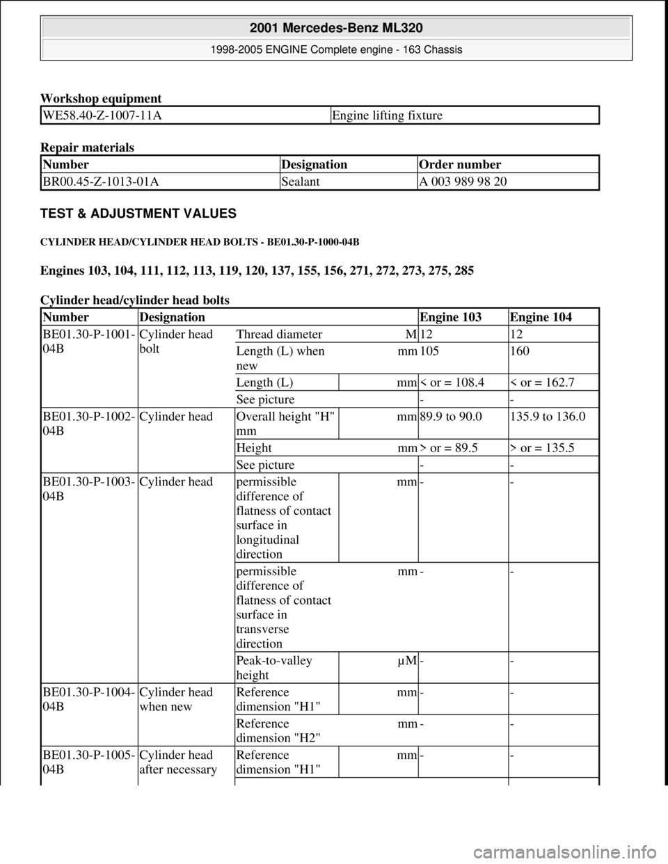
Workshop equipment
Repair materials
TEST & ADJUSTMENT VALUES
CYLINDER HEAD /CYLINDER HEAD BOLTS - BE01.30-P-1000-04B
Engines 103, 104, 111, 112, 113, 119, 120, 137, 155, 156, 271, 272, 273, 275, 285
Cylinder head/cyl inder head bolts
WE58.40-Z-1007-11AEngine lifting fixture
NumberDesignationOrder number
BR00.45-Z-1013-01ASealantA 003 989 98 20
NumberDesignationEngine 103Engine 104
BE01.30-P-1001-
04BCylinder head
boltThread diameterM1212
Length (L) when
newmm105160
Length (L)mm< or = 108.4< or = 162.7
See picture--
BE01.30-P-1002-
04BCylinder headOverall height "H"
mmmm89.9 to 90.0135.9 to 136.0
Heightmm> or = 89.5> or = 135.5
See picture--
BE01.30-P-1003-
04BCylinder headpermissible
difference of
flatness of contact
surface in
longitudinal
directionmm--
permissible
difference of
flatness of contact
surface in
transverse
directionmm--
Peak-to-valley
heightµM--
BE01.30-P-1004-
04BCylinder head
when newReference
dimension "H1"mm--
Reference
dimension "H2"mm--
BE01.30-P-1005-
04BCylinder head
after necessary Reference
dimension "H1"mm--
2001 Mercedes-Benz ML320
1998-2005 ENGINE Complete engine - 163 Chassis
me
Saturday, October 02, 2010 3:17:58 PMPage 140 © 2006 Mitchell Repair Information Company, LLC.
Page 3186 of 4133
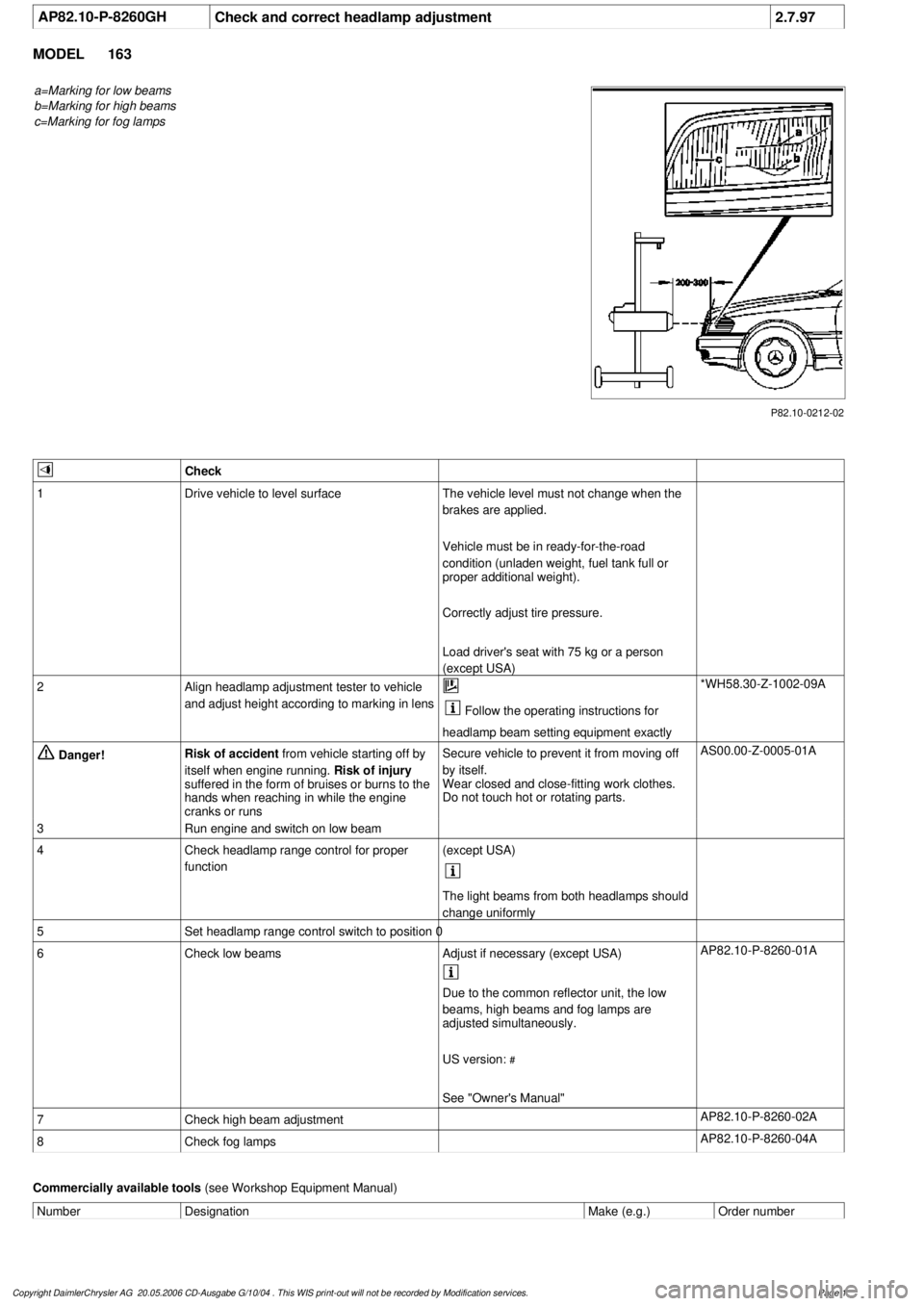
AP82.10-P-8260GH
Check and correct headlamp adjustment
2.7.97
MODEL
163
a=Marking for low beams
b=Marking for high beams
c=Marking for fog lamps
P82.10-0212-02
Check
1
Drive vehicle to level surface
The vehicle level must not change when the
brakes are applied.
Vehicle must be in ready-for-the-road
condition (unladen weight, fuel tank full or
proper additional weight).
Correctly adjust tire pressure.
Load driver's seat with 75 kg or a person
(except USA)
2
Align headlamp adjustment tester to vehicle
and adjust height according to marking in lens
Follow the operating instructions for
headlamp beam setting equipment exactly
*WH58.30-Z-1002-09A
Danger!
Risk of accident
from vehicle starting off by
itself when engine running.
Risk of injury
suffered in the form of bruises or burns to the
hands when reaching in while the engine
cranks or runs
Secure vehicle to prevent it from moving off
by itself.
Wear closed and close-fitting work clothes.
Do not touch hot or rotating parts.
AS00.00-Z-0005-01A
3
Run engine and switch on low beam
4
Check headlamp range control for proper
function
(except USA)
The light beams from both headlamps should
change uniformly
5
Set headlamp range control switch to position 0
6
Check low beams
Adjust if necessary (except USA)
AP82.10-P-8260-01A
Due to the common reflector unit, the low
beams, high beams and fog lamps are
adjusted simultaneously.
US version:
#
See "Owner's Manual"
7
Check high beam adjustment
AP82.10-P-8260-02A
8
Check fog lamps
AP82.10-P-8260-04A
Commercially available tools
(see Workshop Equipment Manual)
Number
Designation
Make (e.g.)
Order number
Copyright DaimlerChrysler AG 20.05.2006 CD-Ausgabe G/10/04 . This WIS print-out will not be recorde
d by Modification services.
Page 1
Page 3193 of 4133
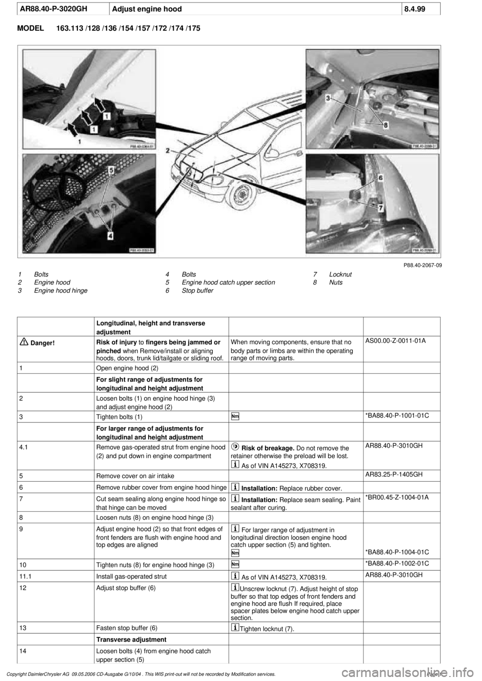
AR88.40-P-3020GH
Adjust engine hood
8.4.99
MODEL
163.113 /128 /136 /154 /157 /172 /174 /175
P88.40-2067-09
1
Bolts
2
Engine hood
3
Engine hood hinge
7
Locknut
8
Nuts
4
Bolts
5
Engine hood catch upper section
6
Stop buffer
Longitudinal, height and transverse
adjustment
Danger!
Risk of injury
to
fingers being jammed or
pinched
when Remove/install or aligning
hoods, doors, trunk lid/tailgate or sliding roof.
When moving components, ensure that no
body parts or limbs are within the operating
range of moving parts.
AS00.00-Z-0011-01A
1
Open engine hood (2)
For slight range of adjustments for
longitudinal and height adjustment
2
Loosen bolts (1) on engine hood hinge (3)
and adjust engine hood (2)
3
Tighten bolts (1)
*BA88.40-P-1001-01C
For larger range of adjustments for
longitudinal and height adjustment
4.1
Remove gas-operated strut from engine hood
(2) and put down in engine compartment
Risk of breakage. Do not remove the
retainer otherwise the preload will be lost.
AR88.40-P-3010GH
As of VIN A145273, X708319.
5
Remove cover on air intake
AR83.25-P-1405GH
6
Remove rubber cover from engine hood hinge
Installation:
Replace rubber cover.
7
Cut seam sealing along engine hood hinge so
that hinge can be moved
Installation:
Replace seam sealing. Paint
sealant after curing.
*BR00.45-Z-1004-01A
8
Loosen nuts (8) on engine hood hinge (3)
9
Adjust engine hood (2) so that front edges of
front fenders are flush with engine hood and
top edges are aligned
For larger range of adjustment in
longitudinal direction loosen engine hood
catch upper section (5) and tighten.
*BA88.40-P-1004-01C
10
Tighten nuts (8) for engine hood hinge (3)
*BA88.40-P-1002-01C
11.1
Install gas-operated strut
As of VIN A145273, X708319.
AR88.40-P-3010GH
12
Adjust stop buffer (6)
Unscrew locknut (7). Adjust height of stop
buffer so that top edges of front fenders and
engine hood are flush If required, place
spacer plates below engine hood catch upper
section.
13
Fasten stop buffer (6)
Tighten locknut (7).
Transverse adjustment
14
Loosen bolts (4) from engine hood catch
upper section (5)
Copyright DaimlerChrysler AG 09.05.2006 CD-Ausgabe G/10/04 . This WIS print-out will not be recorde
d by Modification services.
Page 1
Page 3195 of 4133
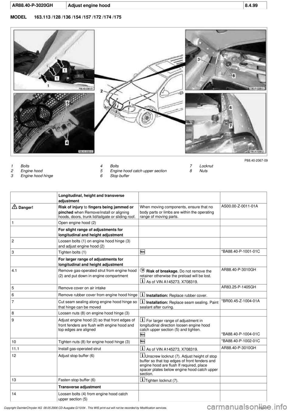
AR88.40-P-3020GH
Adjust engine hood
8.4.99
MODEL
163.113 /128 /136 /154 /157 /172 /174 /175
P88.40-2067-09
1
Bolts
2
Engine hood
3
Engine hood hinge
7
Locknut
8
Nuts
4
Bolts
5
Engine hood catch upper section
6
Stop buffer
Longitudinal, height and transverse
adjustment
Danger!
Risk of injury
to
fingers being jammed or
pinched
when Remove/install or aligning
hoods, doors, trunk lid/tailgate or sliding roof.
When moving components, ensure that no
body parts or limbs are within the operating
range of moving parts.
AS00.00-Z-0011-01A
1
Open engine hood (2)
For slight range of adjustments for
longitudinal and height adjustment
2
Loosen bolts (1) on engine hood hinge (3)
and adjust engine hood (2)
3
Tighten bolts (1)
*BA88.40-P-1001-01C
For larger range of adjustments for
longitudinal and height adjustment
4.1
Remove gas-operated strut from engine hood
(2) and put down in engine compartment
Risk of breakage. Do not remove the
retainer otherwise the preload will be lost.
AR88.40-P-3010GH
As of VIN A145273, X708319.
5
Remove cover on air intake
AR83.25-P-1405GH
6
Remove rubber cover from engine hood hinge
Installation:
Replace rubber cover.
7
Cut seam sealing along engine hood hinge so
that hinge can be moved
Installation:
Replace seam sealing. Paint
sealant after curing.
*BR00.45-Z-1004-01A
8
Loosen nuts (8) on engine hood hinge (3)
9
Adjust engine hood (2) so that front edges of
front fenders are flush with engine hood and
top edges are aligned
For larger range of adjustment in
longitudinal direction loosen engine hood
catch upper section (5) and tighten.
*BA88.40-P-1004-01C
10
Tighten nuts (8) for engine hood hinge (3)
*BA88.40-P-1002-01C
11.1
Install gas-operated strut
As of VIN A145273, X708319.
AR88.40-P-3010GH
12
Adjust stop buffer (6)
Unscrew locknut (7). Adjust height of stop
buffer so that top edges of front fenders and
engine hood are flush If required, place
spacer plates below engine hood catch upper
section.
13
Fasten stop buffer (6)
Tighten locknut (7).
Transverse adjustment
14
Loosen bolts (4) from engine hood catch
upper section (5)
Copyright DaimlerChrysler AG 09.05.2006 CD-Ausgabe G/10/04 . This WIS print-out will not be recorde
d by Modification services.
Page 1