1997 MERCEDES-BENZ ML350 fuel pump
[x] Cancel search: fuel pumpPage 2229 of 4133

AR47.10-P-4000GH
Empty fuel tank if fuel pump is faulty
28.10.97
MODEL
163.113 with ENGINE 612.963
MODEL
163.128 with ENGINE 628.963
MODEL
163.136 with ENGINE 111.977
MODEL
163.154 with ENGINE 112.942
MODEL
163.157 with ENGINE 112.970
MODEL
163.172 with ENGINE 113.942
MODEL
163.174 with ENGINE 113.981
MODEL
163.175 with ENGINE 113.965
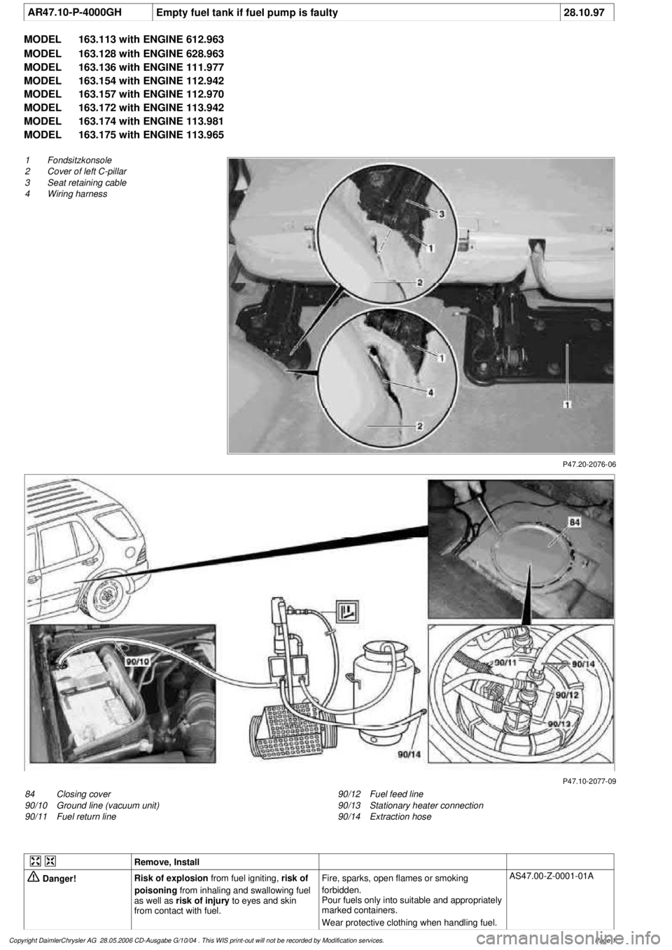
P47.20-2076-06
1
Fondsitzkonsole
2
Cover of left C-pillar
3
Seat retaining cable
4
Wiring harness
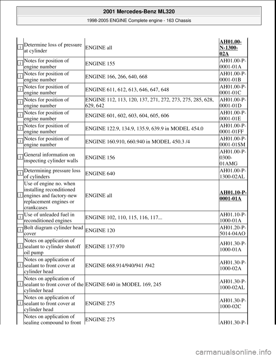
P47.10-2077-09
84
Closing cover
90/10
Ground line (vacuum unit)
90/11
Fuel return line
90/12
Fuel feed line
90/13
Stationary heater connection
90/14
Extraction hose
Remove, Install
Danger!
Risk of explosion
from fuel igniting,
risk of
poisoning
from inhaling and swallowing fuel
as well as
risk of injury
to eyes and skin
from contact with fuel.
Fire, sparks, open flames or smoking
forbidden.
Pour fuels only into suitable and appropriately
marked containers.
Wear protective clothing when handling fuel.
AS47.00-Z-0001-01A
Copyright DaimlerChrysler AG 28.05.2006 CD-Ausgabe G/10/04 . This WIS print-out will not be recorde
d by Modification services.
Page 1
Page 2230 of 4133

1.1
Unscrew bolts at rear of 2/3 seat bench and
raise rear of seat bench
Up to VIN A145272, X708318.
1.2
Remove covers at seat frame of 60% bench
seat
As of VIN A145273, X708319.
AR91.12-P-1100GH
Only remove the covers which are
identified in the document with A, D and E.
2.1
Fold 60% bench seat forward into footwell
As of VIN A145273, X708319. See
operator's manual.
3.1
Pull floor covering below rear seat mounting
bracket (1) of 60% seat forward
Carefully pull floor covering forward under
the seat console to prevent it from tearing.
As of VIN A145273, X708319.
4.1
Pull the floor covering forward under the front
corner of the left C-pillar cover (2)
Carefully pull the floor covering forward
under the cover to prevent it from tearing.
As of VIN A145273, X708319.
5
Cut into floor covering directly behind seat
retaining cable (3)
Ensure that the wiring harness (4) is not
damaged when cutting the floor covering.
As of VIN A145273, X708319. Broken
line marks the cut.
6
Fold floor mat back
Do not crease floor mat!
Fold floor mat back far enough to provide
access to cap (84) between body and fuel
pump.
7
Remove end cover (84) of body
Installation:
Replace cap and insert with
new sealing compound.
Cap (84) is sealed in with body sealer.
Heat with hot air blower to make it easier to
remove.
8
Seal fuel return line (90/11)
Pliers
*163589003700
9
Connect extraction hose (90/14) with adapter
hose to connection for fuel return line (90/11)
Extraction hose
*168589009000
Adapter hose
*163589009100
10
Connect ground cable (90/10) of extraction
pump ground terminal vehicle battery
Pumping out
11
Pump fuel out into safety container using
extraction pump
*BF47.10-P-1001-01A
*WH58.30-Z-1001-16A
12
Install in the reverse order
Fuel tank
Number
Designation
Models
163.113/
136/154/
172 up to
31.08.01
Models
163.113/
136/154/
172 as of
01.09.01
Models
163.157/
175
Model
163.128
Model
163.174
BF47.10-P-1001-01A
Fuel tank capacity
Total capacity
Liter
72838393
Reserve capacity
Liter
10121212
Copyright DaimlerChrysler AG 28.05.2006 CD-Ausgabe G/10/04 . This WIS print-out will not be recorde
d by Modification services.
Page 2
Page 2239 of 4133

AF07.00-P-9000B
Engine runs rough, surges or does not turn over
29.4.02
ENGINE
611 in MODEL 203, 202, 210
ENGINE
612 in MODEL 163, 203, 210, 209
ENGINE
613 in MODEL 210, 220
ENGINE
628 in MODEL 163, 220, 211
ENGINE
646 in MODEL 203, 211
ENGINE
647 in MODEL 211
ENGINE
648 in MODEL 220, 211
ENGINE
668 in MODEL 168
ENGINE
612, 628 in MODEL 463
Modification notes
23.3.01
Supersedes STIP 07.16-014 dated 11.12.00
Damage code
Cause
Remedy
07 206 D5
High-pressure pump
To verify whether high pressure pump is
damaged.
#
High pressure pump of common rail
injection system is damaged mechanically.
1
Remove/install/replace high pressure
pump.
When the high pressure pump of the common
rail injection system is damaged metal chips
and/or damage to the pump drive (timing
drive) can occur due to contamination of the
injection system components.
2
Turn high pressure pump by hand with
driver.
If mechanical resistance can be felt,
perform the following tests. Clarify additional
work with ESKULAB by specifying repair work:
#
3
Check driver of high pressure pump or
mount in sprocket for damage (visual
check).
If high pressure pump is locked:
#
4
Check timing
5
Check timing drive for damage.
In each case:
#
6
Remove/install/replace timing chain.
If timing deviates by a crankshaft angle of
more than 20 degrees (corresponding to one
tooth skipped):
#
7
Check pressure loss.
8
Open low pressure connection on high
pressure pump return (plastic line in
area of pressure regulator valve) and
check connection point in rail for chips.
If chips are present when checking
injection system:
#
9
Thoroughly clean all fuel low pressure
lines as well as feed and return lines.
Flush and blow out with compressed air.
10
Remove fuel preheater and fuel filter
with filter housing, replace.
Fuel preheater is only installed in models
202, 203 and 163.
11
Remove/install/replace fuel cooler at
vehicle and engine end.
Not installed in model 210 up to 6/99 and
model 168.
12
Remove fuel tank, replace.
On engine 628:
#
13
Remove/install/replace electric supply
pump.
14
Remove/install/replace injectors, rail
(including pressure regulation valve and
rail pressure sensor), high pressure
lines and injector leak oil rail.*
Copyright DaimlerChrysler AG 28.05.2006 CD-Ausgabe G/10/04 . This WIS print-out will not be recorde
d by Modification services.
Page 1
Page 2240 of 4133

Fuel pump (gear pump) and electric
shutoff valve can remain on engine.
15
Check injection system for leakage.
16
Check with HHT/DAS for proper
function (check actual value).
17
Read DTC memory and erase after
checking.
Copyright DaimlerChrysler AG 28.05.2006 CD-Ausgabe G/10/04 . This WIS print-out will not be recorde
d by Modification services.
Page 2
Page 2363 of 4133

Determine loss of pressure
at cylinderENGINE all
AH01.00-
N-1300-
02A
Notes for position of
engine numberENGINE 155AH01.00-P-
0001-01A
Notes for position of
engine numberENGINE 166, 266, 640, 668AH01.00-P-
0001-01B
Notes for position of
engine numberENGINE 611, 612, 613, 646, 647, 648AH01.00-P-
0001-01C
Notes for position of
engine numberENGINE 112, 113, 120, 137, 271, 272, 273, 275, 285, 628,
629, 642AH01.00-P-
0001-01D
Notes for position of
engine numberENGINE 601, 602, 603, 604, 605, 606AH01.00-P-
0001-01E
Notes for position of
engine numberENGINE 122.9, 134.9, 135.9, 639.9 in MODEL 454.0AH01.00-P-
0001-01FF
Notes for position of
engine numberENGINE 160.910, 660.940 in MODEL 450.3 /4AH01.00-P-
0001-01SM
General information on
inspecting cylinder wallsENGINE 156
AH01.00-P-
0300-
01AMG
Determining pressure loss
of cylindersENGINE 640AH01.00-P-
1300-02AL
Use of engine no. when
installing reconditioned
engines and factory-new
replacement engines or
crankcases
ENGINE allAH01.10-P-
0001-01A
Use of unleaded fuel in
reconditioned enginesENGINE 102, 110, 115, 116, 117...AH01.10-P-
1000-01A
Bolt diagram cylinder head
coverENGINE 120AH01.20-P-
5014-04AO
Notes on application of
sealant to cylinder shutoff
oil pump
ENGINE 137.970AH01.30-P-
1000-01A
Notes on application of
sealant to front cover at
cylinder head
ENGINE 668.914/940/941 /942AH01.30-P-
1000-02A
Notes on application of
sealant to front cover of the
cylinder head
ENGINE 640 in MODEL 169, 245AH01.30-P-
1000-02AL
Notes on application of
sealant to front cover at
cylinder head
ENGINE 275AH01.30-P-
1000-02C
Notes on application of
sealing compound to front ENGINE 275AH01.30-P-
2001 Mercedes-Benz ML320
1998-2005 ENGINE Complete engine - 163 Chassis
me
Saturday, October 02, 2010 3:17:55 PMPage 7 © 2006 Mitchell Repair Information Company, LLC.
Page 2411 of 4133

housing coolant line
--> (17) from
thermostat housing
15.1Remove radiator Only engine 113.942 /965 /981.AR20.20-P-
3865HC
16Remove brake
pressure regulator
vacuum line (5) from
brake pressure
regulator at rear of
intake manifold
17Extract power
steering pump (19)
oil Hand pumpFig. 50
18Detach return flow
line and pressure line
of power steering
pump (19) Seal connections!
Set of plugsFig. 51
*BA46.30-P-
1002-01A
*BA46.30-P-
1003-01A
19Remove regeneration
vacuum line (6) from
intake pipe
Risk of explosion
caused by ignition of
flammable products,
risk of poisoning
caused by inhaling
fuel vapors or
swallowing fuel as
well as risk of
injury to skin and
eyes exposed to fuel.No fire, sparks, ope n flames or smoking.AS47.00-Z-0001-
01A
Pour fuels only into suitable and appropriately
marked containers.
Wear protective clothing when handling fuel.
20Disconnect fuel line
(4) Release fuel pressure through service valve!
Collect fuel.
M112: ?
*BA07.52-P-
1001-01A
M113: ?
*BA07.52-P-
1001-01A
Pressure hoseFig. 52
21Detach coolant line
(14)
2001 Mercedes-Benz ML320
1998-2005 ENGINE Complete engine - 163 Chassis
me
Saturday, October 02, 2010 3:17:56 PMPage 55 © 2006 Mitchell Repair Information Company, LLC.
Page 2593 of 4133

AR47.20-P-1070HBRemove/install fuel full-flow filter
21.11.97
ENGINE
611.960 /961 /962, 612.961 /963, 613.960 /961
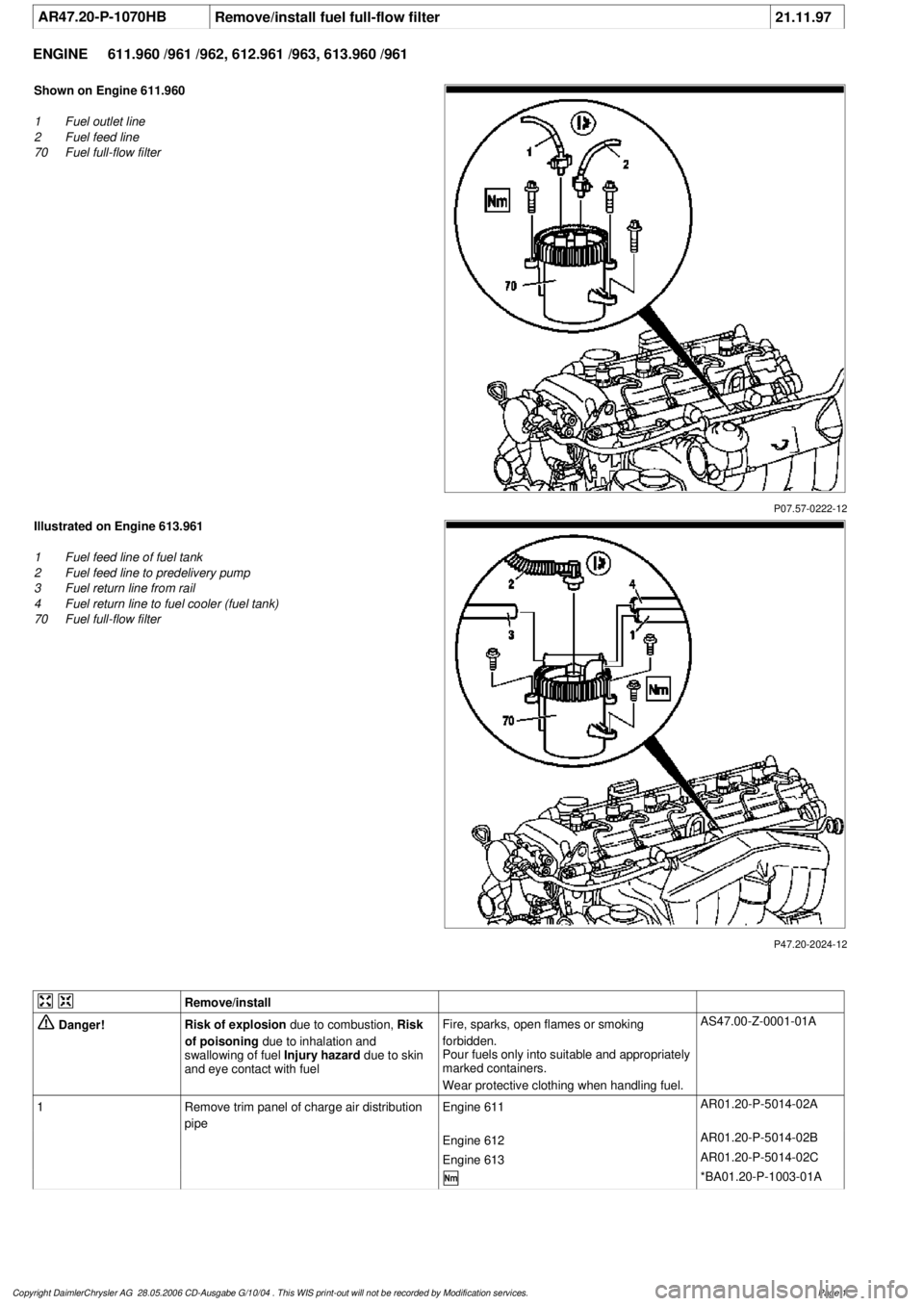
P07.57-0222-12
Shown on Engine 611.960
1
Fuel outlet line
2
Fuel feed line
70
Fuel full-flow filter
P47.20-2024-12
Illustrated on Engine 613.961
1
Fuel feed line of fuel tank
2
Fuel feed line to predelivery pump
3
Fuel return line from rail
4
Fuel return line to fuel cooler (fuel tank)
70
Fuel full-flow filter
Remove/install
Danger!
Risk of explosion
due to combustion,
Risk
of poisoning
due to inhalation and
swallowing of fuel
Injury hazard
due to skin
and eye contact with fuel
Fire, sparks, open flames or smoking
forbidden.
Pour fuels only into suitable and appropriately
marked containers.
Wear protective clothing when handling fuel.
AS47.00-Z-0001-01A
1
Remove trim panel of charge air distribution
pipe
Engine 611
AR01.20-P-5014-02A
Engine 612
AR01.20-P-5014-02B
Engine 613
AR01.20-P-5014-02C
*BA01.20-P-1003-01A
Copyright DaimlerChrysler AG 28.05.2006 CD-Ausgabe G/10/04 . This WIS print-out will not be recorde
d by Modification services.
Page 1
Page 2595 of 4133

AF54.30-P-2064A
Fuel gauge not registering correctly after refueling vehicle
4.2.03
MODEL
163.### #A as of 221506 up to 364039,
163.### #X as of 734088 up to 777100
Operation no. of operation texts or standard texts and flat rates
Sector
Op. no.
Operation text
Time
Acc. no.
Code
P
023803
RECODE INSTRUMENT CLUSTER
003 WU/0.3 h
54 208 50
---
Damage Code
Cause
Remedy
Refuel recognition software may not
recognize incremental refueling (< 7 L).
In case of complaint
#
The fuel gauge operation defaults to back-
up mode, and continuously decreases last
stored sensor value based on consumption
data supplied via engine management. This
continues until either refuel recognition or
instrument cluster (A1) reset occurs (via
STAR Diagnosis or power disconnect).
Vehicles with 83 L fuel tank (as of MY2002)
are more susceptible to this condition.
This applies only to instrument clusters
(A1) with diagnostic version 3/05, 3/06,
and 3/07.
1
Connect STAR Diagnosis.
2
Under "Control module adaptations" in
"ICM" menu, set "Fuel tank characteristic
curve" from "Normal" to "Direct sensor
value".
DO NOT replace the instrument cluster
(A1) or fuel pump assembly (M3) for this
condition.
Copyright DaimlerChrysler AG 28.05.2006 CD-Ausgabe G/10/04 . This WIS print-out will not be recorde
d by Modification services.
Page 1