1997 MERCEDES-BENZ ML350 coolant capacity
[x] Cancel search: coolant capacityPage 2584 of 4133

8
Disconnect coolant feed hose (3) to fuel cooler
Raise fuel cooler.
Hose clamp pliers (length 210 mm;
adjustment range 80 mm)
*WH58.30-Z-1026-02A
9
Install in the reverse order
Danger!
Risk of accident
as vehicle may start off by
itself with the engine running.
Risk of injury
as working around the engine during start-up
or while running may result in contusions and
burns
Secure vehicle to prevent it from moving off
by itself.
Wear closed and tight-fitting work clothes.
Do not grasp hot or rotating parts.
AS00.00-Z-0005-01A
10
Pour in coolant
*BF20.00-P-1001-02E
Switch heater to maximum and warm up
engine at moderate revs. Top up coolant
constantly at coolant expansion reservoir.
Close coolant expansion reservoir once
coolant temperature is 60-70 °C.
Note on coolant level
Models 124, 129, 140, 168, 170, 202, 208,
210, 220, 463
AH20.00-P-1142-01A
11
Inspect cooling system for leaks
AR20.00-P-1010HA
12
Run engine and inspect fuel system for leaks
Crankcase ventilation, cylinder head cover
Number
Designation
Engine
612.963
BA01.20-P-1002-01A
Screw of trim panel of cylinder head cover
to cylinder head cover
NM
10
BA01.20-P-1003-01A
Screw attaching cover panel to charge air
distribution pipe
NM
10
Cooling system
Number
Designation
Engine
612.963
BF20.00-P-1001-02E
Cooling system
Total capacity
Liter
Y
11,0
Capacity of anticorrosion/
antifreeze agent down to -37 °C
Liter
Y
5,5
Capacity of anticorrosion/
antifreeze agent down to -45 °C
Liter
Y
6,25
Specifications for Service
Products
SheetBB00.40-P-0310-01A
SheetBB00.40-P-0325-02A
129 589 00 91 00
Set of closure plugs
Circuit
000 589 54 37 00
Commercially available tools
(see Workshop Equipment Manual)
Number
Designation
Make (e.g.) g.)
Order number
Copyright DaimlerChrysler AG 28.05.2006 CD-Ausgabe G/10/04 . This WIS print-out will not be recorde
d by Modification services.
Page 2
Page 3343 of 4133
This input information is relayed by the CDI control module (N3/9) to the integrated control module of the
electric engine/AC intake fan with integrated control (M4/7).
Engines 113.942 and 113.981
The all-activity module (AAM) (N10) receives the coolant temperature via the coolant temperature sensor and
the refrigerant pressure via the refrigerant pressure sensor (B12).
This input information is relayed by the all-activity module (AAM) (N10) to the integrated control module of
the engine and AC electric suction fan with integrated control (M4/7)
There the input information is compared with the stored values and, if necessary, the speed of the engine and
AC electric suction fan with integrated control (M4/7) is increased to 100 %.
The engine and AC electric suction fan with integrated control (M4/7) operates with AC switched on and in the
reheat mode for basic ventilation with a capacity of up to 20 %.
The basic ventilation can be switched off under the following conditions:
At an outdoor temperature of < or = 15°C the value of the outdoor temperature is transmitted from the
outside temperature sensor (B10/5) to the AC control module (N19).
The pressure-dependent fan speed remains the same.
At a vehicle speed of > 75 km/h
The vehicle speed value comes from the traction system control module via the instrument cluster (A1)
and CDI control module (N3/9), to the control module integrated in the electric suction fan engine and
AC with integrated control (M4/7). The pressure-dependent fan speed remains the same.
An overrun time of 60 s can be set in order to ensure that the engine and AC electric suction fan with integrated
control (M4/7) will continue to operate even where the refrigerant compressor is temporarily switched off by
the icing protection.
The engine and AC electric suction fan with integrated control (M4/7) has a power rating of 550W.
ELECTRIC FAN, ENGINE/AIR CONDITIONING, LOCATION - GF83.40-P-2118-02GH
The engine and AC electric suction fan with integrated control (M4/7) is located immediately in front of the
condenser.
2001 Mercedes-Benz ML320
1998-2005 HVAC Climate Control - 163 Chassis
me
Saturday, October 02, 2010 3:23:16 PMPage 99 © 2006 Mitchell Repair Information Company, LLC.
Page 3359 of 4133
ENGINE AND AC ELECTRIC SUCTION FAN WITH INTEGRATED CONTROL, FUNCTION - GF83.40-P-2172-01GI
Function
Depending on the refrigerant pressure and/or on the coolant temperature the speed of the engine and AC electric
suction fan with integrated control (M4/7) is increased infinitely.
The engine and AC electric suction fan with integrated control (M4/7) receives the coolant temperature from the
coolant temperature sensor (B11/4) and the refrigerant pressure from the refrigerant pressure and temperature
sensor (B12/2).
This input information is compared by the engine and AC electric suction fan with integrated control (M4/7)
with the stored values and, if necessary, the speed of the engine and AC electric suction fan is increased to 100
%
The engine and AC electric suction fan with integrated control (M4/7) operates with AC switched on and in the
reheat mode for basic ventilation with a capacity of up to 20 %.
The basic ventilation can be switched off under the following conditions:
At an outside temperature of < or = 15°C.
The pressure-dependent fan speed remains the same.
At a driving speed of > 75 km/h.
The pressure-dependent fan speed remains the same.
An overrun time of 60 s can be set in order to ensure that the engine and AC electric suction fan with integrated
control (M4/7) will continue to operate even where the refrigerant compressor is temporarily switched off by
the icing protection.
The engine and AC electric suction fan with integrated control (M4/7) has a power rating of 850 W.
ELECTRIC SUCTION-TYPE FAN FOR ENGINE AND AC WITH INTEGRATED CONTROL, LOCATION/TASK/FUNCTION
- GF83.40-P-2172GI
MODEL 163 as of 1.9.01 with ENGINE 113.965 /981, 612.963, 628.963 with CODE (580a) Automatic air
conditioning
MODEL 163 as of 1.9.01 up to 31.8.02 with ENGINE 113.942 with CODE (580a) Automatic air
conditioning
and temperature sensor,
function GF83.40-P-
2171-01GI
2001 Mercedes-Benz ML320
1998-2005 HVAC Climate Control - 163 Chassis
me
Saturday, October 02, 2010 3:23:16 PMPage 115 © 2006 Mitchell Repair Information Company, LLC.
Page 3381 of 4133
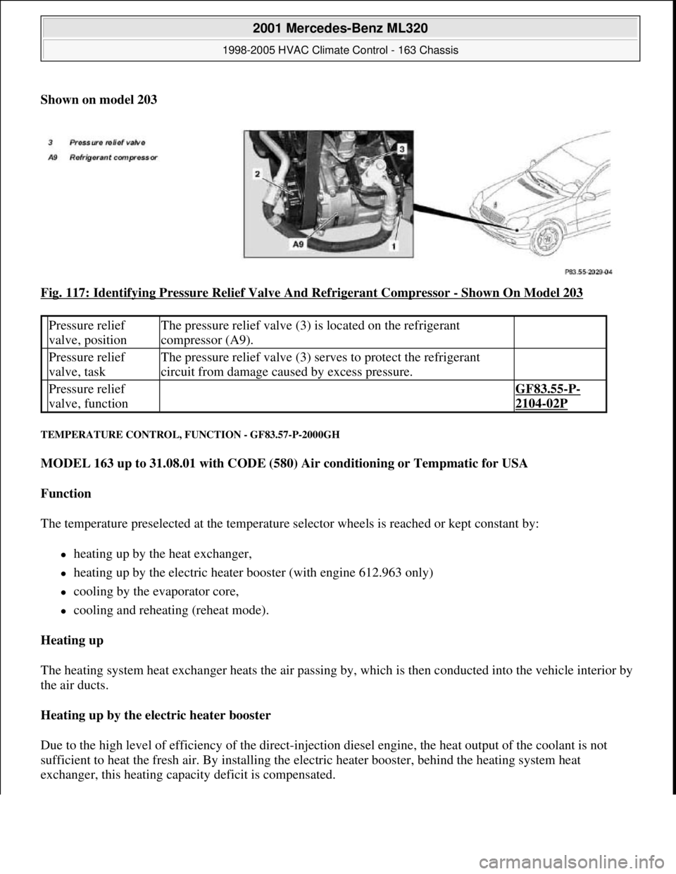
Shown on model 203
Fig. 117: Identifying Pressure Relief Valve And Refrigerant Compressor
- Shown On Model 203
TEMPERATURE CONTROL, FUNCTION - GF83.57-P-2000GH
MODEL 163 up to 31.08.01 with CODE (580) Air conditioning or Tempmatic for USA
Function
The temperature preselected at the temperature selector wheels is reached or kept constant by:
heating up by the heat exchanger,
heating up by the electric heater booster (with engine 612.963 only)
cooling by the evaporator core,
cooling and reheating (reheat mode).
Heating up
The heating system heat exchanger heats the air passing by, which is then conducted into the vehicle interior by
the air ducts.
Heating up by the electric heater booster
Due to the high level of efficiency of the direct-injection diesel engine, the heat output of the coolant is not
sufficient to heat the fresh air. By installing the electric heater booster, behind the heating system heat
exchanger, this heating capacity deficit is compensated.
Pressure relief
valve, positionThe pressure relief valve (3) is located on the refrigerant
compressor (A9).
Pressure relief
valve, taskThe pressure relief valve (3) serves to protect the refrigerant
circuit from damage caused by excess pressure.
Pressure relief
valve, function GF83.55-P-
2104-02P
2001 Mercedes-Benz ML320
1998-2005 HVAC Climate Control - 163 Chassis
me
Saturday, October 02, 2010 3:23:17 PMPage 137 © 2006 Mitchell Repair Information Company, LLC.
Page 3404 of 4133
HEATER, DIAGNOSIS, BASIC KNOWLEDGE - AD83.20-P-2000GH
MODEL 163
HEATER CAPACITY, FUNCTION CHECK, HEATER - AD83.20-P-3000-01GH
Test sequence
Heater switch (2) on "red" stop
Blower switch (1) on stage 4
Air distribution switch (3) in 12 o'clock position
Recirculated air button ( ) not pressed (LED does not come on)
Test period > 5 minutes
Engine speed 2000 rpm
Engine coolant temperature > 80°C
Read out temperature measuring instrument (4)
Temperature display > 55°C
If the measured values stated above are not achieved, the following components and functions should be
checked:
Engine coolant temperature
Furring in cooling system and heat exchanger
Blend air flap function
Coolant circulation pump (M13)
WH58.30-Z-1002-08ADigital temperature measuring instrument (measuring range -20° to +70°)
WH58.30-Z-1004-08AAir temperature probe
Electric wiring diagrams, location of ground points and connectors PE83.00-P-1100E
Connection and use of test equipment AD00.00-P-1000AZ
Diagnosis tools, heater AD83.20-P-2000-01GC
2001 Mercedes-Benz ML320
1998-2005 HVAC Climate Control - 163 Chassis
me
Saturday, October 02, 2010 3:23:17 PMPage 160 © 2006 Mitchell Repair Information Company, LLC.
Page 3405 of 4133
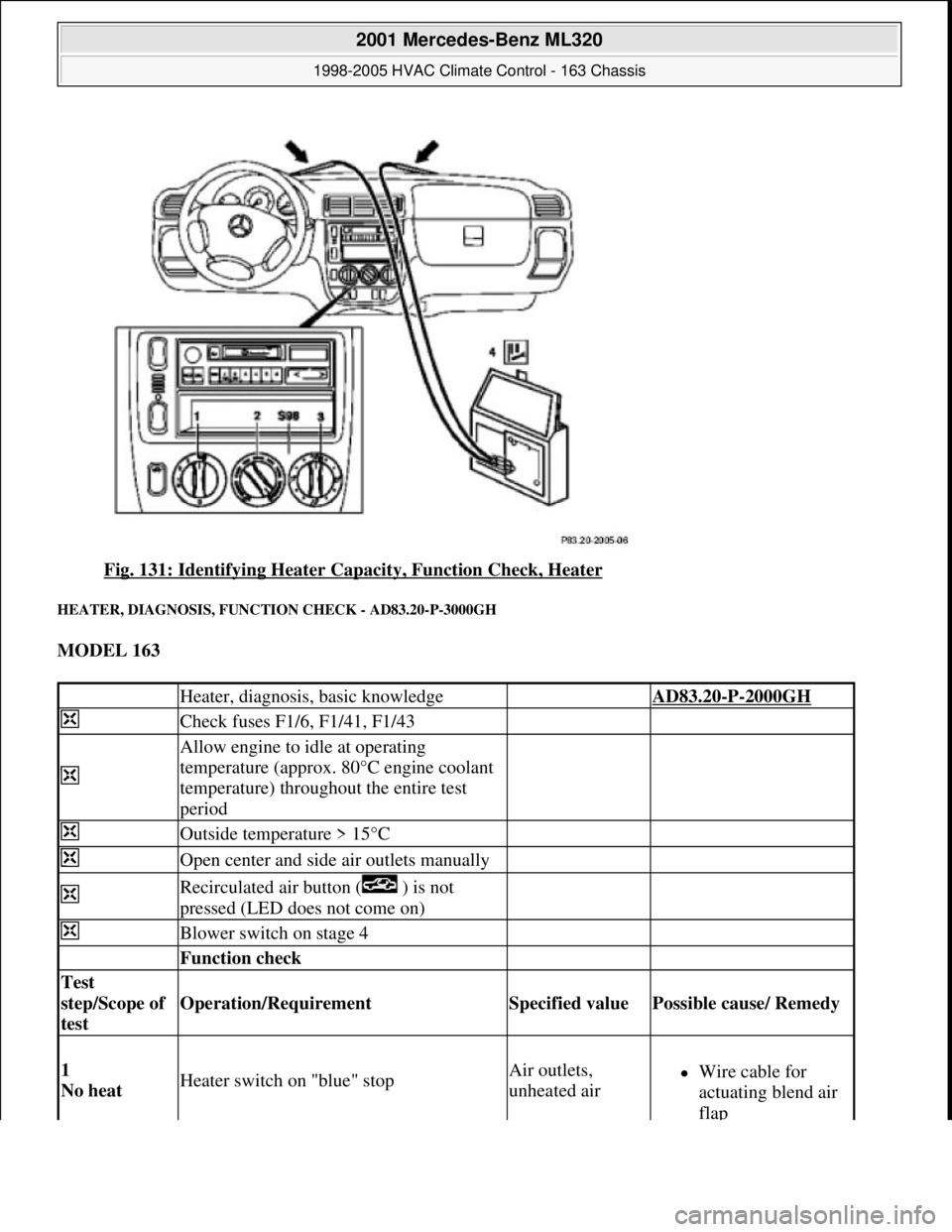
Fig. 131: Identifying Heater Capacity, Function Check, Heater
HEATER, DIAGNOSIS, FUNCTION CHECK - AD83.20-P-3000GH
MODEL 163
Heater, diagnosis, basic knowledge AD83.20-P-2000GH
Check fuses F1/6, F1/41, F1/43
Allow engine to idle at operating
temperature (approx. 80°C engine coolant
temperature) throughout the entire test
period
Outside temperature > 15°C
Open center and side air outlets manually
Recirculated air button ( ) is not
pressed (LED does not come on)
Blower switch on stage 4
Function check
Test
step/Scope of
test
Operation/Requirement Specified value Possible cause/ Remedy
1
No heat Heater switch on "blue" stopAir outlets,
unheated airWire cable for
actuating blend air
flap
2001 Mercedes-Benz ML320
1998-2005 HVAC Climate Control - 163 Chassis
me
Saturday, October 02, 2010 3:23:17 PMPage 161 © 2006 Mitchell Repair Information Company, LLC.
Page 3762 of 4133

13
Disconnect coolant hose to coolant pump (8),
coolant hose from thermostat housing (9) and
coolant hose from coolant expansion tank
(10) at radiator
Hexagon socket wrench
*WH58.30-Z-1001-06A
Hexagon socket wrench
*WH58.30-Z-1002-06A
14
Detach air guides (12)
Installation:
Replace fastening clamps
(13)
15
Unscrew bolts (16) at condenser (17) to
radiator
Avoid deformation of condenser lines.
Do not disconnect lines.
16
Remove attachment parts (20) and rubber
shock absorber (21)
Installation:
Ensure, that the rubber
shock absorbers do not drop when installing
the radiator.
Replace fastening clamps.
17
Take off fluid reservoir of AC (14) at radiator
Place to the side with lines connected.
External torx set
*001589760900
18
Remove bracket of charge air pipe at left
radiator
Installation:
Insert bracket of charge air
pipe into the bracket at the radiator.
19
Remove radiator (15)
Installation:
When installing, the mounting
studs of the radiator must be inserted into the
rubber grommets of the lower crossmember.
20
Install in the reverse order
21
Check headlamp adjustment, correct if
necessary
e
Check and correct headlamp adjustment
AP82.10-P-8260A
22
Inspect cooling system for leaks
AR20.00-P-1010HA
23
Fill power steering pump and bleed
Danger!
Risk of accident
caused by vehicle starting
off by itself when engine is running.
Risk of
injury
caused by contusions and burns when
working in engine during starting procedure
Secure vehicle to prevent it from moving.
Wear closed and snug-fitting work clothes.
Do not grasp hot or rotating parts.
AS00.00-Z-0005-01A
24
Run engine and inspect for leaks
Crankcase ventilation, cylinder head cover
Number
Designation
Engine
612.963
BA01.20-P-1002-01A
Bolt, cylinder head cover trim panel to
cylinder head cover
Nm
10
BA01.20-P-1003-01A
Bolt, cover panel to charge air distribution
pipe
Nm
10
Power steering pump
Number
Designation
Model
163.113
BA46.30-P-1012-01A
Banjo bolt, power steering oil line to radiator
Nm
30
Cooling system
Number
Designation
Engine
612.963
BF20.00-P-1001-02E
Cooling system
Total capacity
Liter
Y
11.0
Copyright DaimlerChrysler AG 12.05.2006 CD-Ausgabe G/10/04 . This WIS print-out will not be recorde
d by Modification services.
Page 3
Page 3773 of 4133

BA20.10-P-1002-01F
Bolt of coolant thermostat housing to
crankcase
Nm
9
Designation
Engine
647, 648
Engine
646.951/
961
Engine
646.962/
963
BA20.10-P-1002-01G
Bolt of coolant thermostat housing to cylinder head
Nm
999
Designation
Engine
611.960
Engine
611.961
Engine
611.962
BF20.00-P-1001-02E
Cooling system
Total capacity
Liters
8.0
Y
10.3
Y
11.9
Capacity of anticorrosion/
antifreeze agent down to
-37 °C
Liters
4.0
Y
5.2
Y
6.0
Capacity of anticorrosion/
antifreeze agent down to
-45 °C
Liters
4.5
Y
5.7
Y
6.5
Specifications for Operating
Fluids
SheetBB00.40-P-0310-01ABB00.40-P-0310-01ABB00.40-P-0310-01A
SheetBB00.40-P-0325-00ABB00.40-P-0325-00ABB00.40-P-0325-00A
Cooling system
Number
Designation
Engine
612.961
Engine
612.962/ 967
Engine
612.963
BF20.00-P-1001-02E
Cooling system
Total capacity
Liters
Y
10.6
Y
12.4
Y
11.0
Capacity of anticorrosion/
antifreeze agent down to
-37 °C
Liters
Y
5.3
Y
6.2
Y
5.5
Capacity of anticorrosion/
antifreeze agent down to
-45 °C
Liters
Y
5.8
Y
6.8
Y
6.25
Specifications for Operating
Fluids
SheetBB00.40-P-0310-01ABB00.40-P-0310-01ABB00.40-P-0310-01A
SheetBB00.40-P-0325-00ABB00.40-P-0325-00ABB00.40-P-0325-00A
Cooling system
Number
Designation
Engine
613.960
Engine
613.961
Engine
628.960
BF20.00-P-1001-02E
Cooling system
Total capacity
Liters
Y
15.5
Y
11.2
Y
16.5
Capacity of anticorrosion/
antifreeze agent down to
-37 °C
Liters
Y
7.75
Y
5.6
Y
8.25
Capacity of anticorrosion/
antifreeze agent down to
-45 °C
Liters
Y
8.0
Y
6.2
Y
9.1
Specifications for Operating
Fluids
SheetBB00.40-P-0310-01ABB00.40-P-0310-01ABB00.40-P-0310-01A
SheetBB00.40-P-0325-00ABB00.40-P-0325-00ABB00.40-P-0325-00A
Copyright DaimlerChrysler AG 12.05.2006 CD-Ausgabe G/10/04 . This WIS print-out will not be recorde
d by Modification services.
Page 3