1997 MERCEDES-BENZ ML350 automatic transmission fluid
[x] Cancel search: automatic transmission fluidPage 1129 of 4133

325 Index
F
Fastening the seat belts 42
Fine adjustment
Cruise control 152
First aid kit 257
Flat tire 274
Lowering the vehicle 276
Mounting the spare wheel 274
Preparing the vehicle 274
Spare wheel 259
Flexible Service System (FSS) 232, 312
Fluid level
Automatic transmission 222
Fog lamp, rear 267
Fog lamps 111
Replacing bulbs 266
Fog lamps, front
Replacing bulbs 267
Switching on 111
Folding
Exterior mirrors 128
Folding electrically
Exterior rear view mirrors
1284-ETS 25, 79
Indicator lamp 252
LOW RANGE mode 80
Malfunction indicator lamp 252
Warning lamp 251
Front airbags 63
Front fog lamps
Indicator lamp 253
Front lamps
Replacing bulbs 266, 268
Front towing eyes 285
FSS (Flexible Service System) 232, 312
Fuel 215
Additives 303
Fuel reserve warning lamp 252
Gasoline additives 303
Premium unleaded gasoline 215,
303
Requirements 303
Reserve warning 25
Fuel additives 303
Fuel filler flap 214
Locking 214
Opening 263
Unlocking 214
Fuel requirements 303Fuel tank
Filler flap 214
Fuels, coolants, lubricants etc. 300
Functions
Trip computer* 186
Fuse box 287, 288
Fuse chart 287
Fuses 287
F us e box i n engi ne com p art me nt 2 87
Fuse box in passenger footwell 288
Fuse chart 287
Fuse extractor 287
Spare fuses 287
G
Garage door opener 29, 180
Erasing in remote control 185
Gasoline see Fuel 215
Gasoline additives 303
Gauge for
Coolant temperature 25
Fuel 25
Outside temperature 25
Page 1130 of 4133

326 IndexGear range 312
Automatic transmission 121
Limiting 121
Shifting into optimal 120
Gear range limit
Canceling 120
Gear selector lever
Cleaning 238
Position 122
Glass breakage sensor 84
Global Positioning System (GPS) 312
Glossary 311
Glove box 23, 164
Closing 164
Opening 164
Good visibility 126
GPS 312H
Hard plastic trim items
Cleaning 238
Hazard warning flasher 112
Switching off 112
Switching on 112
Head restraints
Manual seats 36
Power seats* 38
Headlamp aim
Adjusting 272
Headlamp cleaning system* 224
Headlamps
Automatic control 108
Bi-Xenon* 311
Cleaning 236
Cleaning system* 131, 224
Refilling washer fluid 224
Switching off 54
Switching on 48
Washer fluid 307
Washer system 307Headliner
Cleaning 238
Heated seats* 98
Height adjustment
Head restraints 36, 38
Seat belts 45
Steering wheel 39
High beam flasher 49, 110
High beam headlamps
Replacing bulbs 266, 269
Switching on 110
High mounted brake lamp 267
Replacing bulbs 271
Hood 217
Closing 218
Opening 217
Hooks
Loading 159
Hydroplaning 197
Page 1133 of 4133

329 Index
Lighting 107
Automatic headlamp mode 108
Cargo compartment 114
Combination switch 110
Daytime running lamp mode 109
Door entry lamps 113
Front fog lamps 111
High beam flasher 110
High beams 110
Instrument cluster illumination 116
Interior 112
Locator lighting 110
Night security illumination 109
Limiting the gear range 121
Limp Home Mode 124
Line of fall 313
Loading 157
Cargo area cover blind* 161
Cargo floor plates 162
Cargo tie-down rings 158
Hooks 159
Instructions 157, 158
Partition net* 159
Roof rack 163Split rear bench seat 99
Trailer 208
Locator lighting 110
Lock button 313
Locking 88
Automatic while driving 93
Centrally from inside 94
Fuel filler flap 214
Global 89
Vehicle in an emergency 262
Locking knobs 32
Loss of keys 90
Loss of Service and Warranty Information
Booklet 291
Low beam headlamps
Replacing bulbs 266, 268
Switching on 48
Low engine oil level
Indicator lamp 253
LOW RANGE - 4-ETS 80
LOW RANGE - ABS 77LOW RANGE - ESP 81
LOW RANGE mode 125
Low washer system fluid level
Indicator lamp 253
Lowering
Vehicle 276
M
Main dimensions 298
Maintenance 12
Display messages 256
Manual operations
Fuel filler flap 263
Interior lighting control 113
Locking the vehicle 262
Sliding/pop-up roof* 265
Unlocking the driver’s door 261
Unlocking transmission selector
lever 264
Page 1141 of 4133

337 Index
Sun visor 132
Supplemental Restraint System
(SRS) 314
Switching off
Automatic climate control 137
ESP 81
Hazard warning flasher 112
Headlamps 54
Rapid seat heating 99
Transmission control – LOW RANGE
mode 125
Switching on
Automatic climate control 137
ESP 82
Front fog lamps 111
Front fog lamps, rear fog lamp 111
Hazard warning flasher 112
Headlamps 48
High beams 110
Rapid seat heating* 98
Seat heating* 98
Transmission control – LOW RANGE
mode 125
Trip computer* 186
Windshield wipers 49Synchronizing
ESP 246
Power windows 146
Remote control 263
Sliding/pop-up roof* 149
T
Tachometer 26, 118
Displaying gear range 121
Tail lamps 270
Cleaning 236
Replacing bulbs 267Tar stains 235
Technical data 302
Brake fluid 302
Coolants 304
Electrical system 297
Engine 294
Engine oil 302
Engine oil additives 302
Fuel requirements 303
Gasoline additives 303
Main dimensions 298
Premium unleaded gasoline 303
Rims and tires 295
Weights 299
Windshield and headlamp washer
system 307
Tele Aid System* 315
Page 1177 of 4133

Fig. 4: Removing & Installing Transmission With Torque Converter
Courtesy of MERCEDES-BENZ OF NORTH AMERICA.
Remove/Install -
1 - Disconnect ground cable of battery. See DISCONNECT GROUND LEAD FROM BATTERY
.
2 - Remove transfer case. See TRANSFER CASE .
3 - Unbolt oil filler pipe (3) from crankcase. See Fig. 4
.
4 - Remove heat shield (5) and disconnect 13-pin plug connector (2).
5 - Remove locking clips (21) and remove shift.
6 - Unscrew oil drain screw on oil pan (14).
7.1 - Unscrew oil drain screw for torque converter (15).
8.1 - Detach wire for park lock interlock (7) at transmission.
9 - Lambda sensors for primary catalytic converters remove.
10 - Unscrew oil lines (4) to oil cooler from transmission.
11 - Remove cover in oil pan (18) and disconnect torque converter from driven plate at flange.
12 - Unscrew bolts of transmission (19) at crankcase and take out transmission downwards at an angle
using a lifting device. NOTE: Code radio, set clock, normalize power windows and set timer in vehicles
with stationary heater.
NOTE: Adjust shift rod using pliers. See Fig. 10
.
NOTE: If the transmission fluid is burnt or contains wear particles, the oil cooler
lines and oil cooler must be flushed out: Flush oil cooler and oil cooler
lines.
NOTE: Only up to A145272,X708318. For installation and removal, position
selector lever or range selector lever in position "P" and leave in position
"P" when cable/transmission is removed. See REMOVING & INSTALLING
WIRE CABLE/TRANSMISSION FOR PARKING SHIFT LOCK ON
TRANSMISSION.
NOTE: Only up to A145272, X708318.
Upon Installation: Adjust cables for parking shift lock. See ADJUSTING
WIRE CABLES FOR PARKING LOCK INTERLOCK.
NOTE: Upon Installation: Check function of parking shift lock.
2001 Mercedes-Benz ML320
1998-03 AUTOMATIC TRANSMISSIONS Complete Transmissions - ML 320 - 722.662
me
Saturday, October 02, 2010 3:15:25 PMPage 8 © 2006 Mitchell Repair Information Company, LLC.
Page 1370 of 4133

Operation
The term power transmission refers to the transmission of propulsion power and engine torques. Via the
mechanical/hydraulic connection between the engine, torque converter and the downstream automatic
transmission the engine torques are transmitted to the driving wheels and are converted in the transmission via
several planetary gear sets.
Power is transferred in the torque converter via the driven impeller by diverting hydraulic fluid to the turbine
wheel, which is connected to the input shaft. See Fig. 117
.
When the torque converter lockup clutch is engaged, power is transmitted via this mechanical connection. Via
the gear wheels of the individual planetary gear sets the torques coming from the converter are passed on to the
output shaft with the aid of freewheels, multi-disk clutches and brakes, depending on the ratio and shift element
operated.
A reduction of the output speed in the low gears provides lower vehicle speeds with high tractive forces and
drive torques at the drive wheels.
Power Flow In 1st Gear, Function
See POWER FLOW IN 1ST GEAR, FUNCTION
.
Power Flow In 2nd Gear, Function
See POWER FLOW IN 2ND GEAR FUNCTION
.
Power Flow In 3rd Gear, Function
See POWER FLOW IN 3RD GEAR FUNCTION
.
Power Flow In 4th Gear, Function
See POWER FLOW IN 4TH GEAR FUNCTION
.
Power Flow In 5th Gear, Function
See POWER FLOW IN 5TH GEAR FUNCTION
.
Power Flow In Reverse, Function
See POWER FLOW IN REVERSE, FUNCTION
.
Function Of Torque Converter Lock-Up Clutch Control
See FUNCTION OF TORQUE CONVERTER LOCKUP CLUTCH CONTROL
.
Power Flow In 1st Gear, Function
2001 Mercedes-Benz ML320
1998-03 AUTOMATIC TRANSMISSIONS Complete Transmissions - ML 320 - 722.662
me
Saturday, October 02, 2010 3:15:28 PMPage 201 © 2006 Mitchell Repair Information Company, LLC.
Page 1821 of 4133

WINDSHIELD WIPERS, WINDSHIELD WASHER SYSTEM - OPERATIONAL INSPECTION - AP82.35-P-8252GH
MODEL 163
Modification notes
RETROFITTING & CONVERSION
RETROFITTING WIRING HARNESS - AN82.61-P-0001-01H
Model 163 with automatic transmission
1. Prepare adapter wirin
g harness (4) as shown in figure.
Checking
1Check fluid level in
windshield washer fluid
reservoir and adjust to
correct level
See table on packaging
for mixing ratio MB
windshield washer fluid
concentrate conforming
to Specifications for
Service Products sheet
371.
12.1.05Check wiper blades,
deletedStep 2
Check
1Check operation of spray
nozzles Use a suitable needle
to clean blocked spray
nozzles from the outside
2Check setting of wiper
arms The end of the wiper
arm must be parallel with
the windshield. If
necessary correct the
stagger of the wiper arm
accordingly.
2001 Mercedes-Benz ML320
1998-2005 ACCESSORIES & BODY, CAB Electrical System - Body - 163 Chassis
me
Saturday, October 02, 2010 3:30:10 PMPage 326 © 2006 Mitchell Repair Information Company, LLC.
Page 3046 of 4133

For these vehicles the service sheet for the Active Service System (ASSYST) and the maintenance manual
volume 4 apply.
With the ASSYST service sheet the previous distinction between care service and maintenance service no
longer applies. Instead, the service category A (minor service) and service category B (major service) have been
introduced.
The service scopes for each model series can be seen in the respective valid service sheet.
The order no. is stated on the particular SERVICE SHEET.
On manual transmissions, automatic transmissions, transfer cases, front axles and rear axles the service item
"Check fluid level" has been replaced by an inspection of all visible parts for leaks.
In view of the fact that these components are not oil consumers, as is the case for the engine, a loss of oil can
occur only to the outside.
If any leaks are present, the procedure, as before, is to determine the cause and to rectify it subject to a separate
repair order.
The service operations carried out should be documented in the boxes in front of the operation titles. It is
essential to ensure that the specified service operations are carried out in full.
An indication is given in the boxes after the operation titles of which service operations should be carried out
for service category A (minor service) or service category B (major service). Enter a cross behind these boxes to
identify any items which are not in proper order when the vehicle is received.
Additional operations should be defined by the service adviser in agreement with the customer and an indication
should be made on the service sheet whether these additional operations are to be carried out.
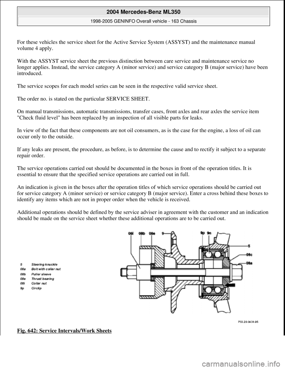
Fig. 642: Service Intervals/Work Sheets
2004 Mercedes-Benz ML350
1998-2005 GENINFO Overall vehicle - 163 Chassis
me
Saturday, October 02, 2010 3:47:52 PMPage 401 © 2006 Mitchell Repair Information Company, LLC.