Page 2143 of 4133

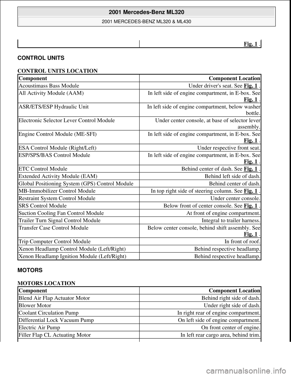
CONTROL UNITS
CONTROL UNITS LOCATION
MOTORS
MOTORS LOCATION
Fig. 1 .
ComponentComponent Location
Acoustimass Bass ModuleUnder driver's seat. See Fig. 1 .
All Activity Module (AAM)In left side of engine compartment, in E-box. See
Fig. 1
.
ASR/ETS/ESP Hydraulic UnitIn left side of engine compartment, below washer
bottle.
Electronic Selector Lever Control ModuleUnder center console, at base of selector lever
assembly.
Engine Control Module (ME-SFI)In left side of engine compartment, in E-box. See
Fig. 1
.
ESA Control Module (Right/Left)Under respective front seat.
ESP/SPS/BAS Control ModuleIn left side of engine compartment, in E-box. See
Fig. 1
.
ETC Control ModuleBehind center of dash. See Fig. 1 .
Extended Activity Module (EAM)Behind left side of dash.
Global Positioning System (GPS) Control ModuleBehind center of dash.
MB-Immobilizer Control ModuleIn top right side of steering column. See Fig. 1 .
Restraint System Control ModuleUnder center console.
SRS Control ModuleBelow front of center console. See Fig. 1 .
Suction Cooling Fan Control ModuleAt front of engine compartment.
Trailer Turn Signal Control ModuleIntegral to trailer harness.
Transfer Case Control ModuleBelow center console, behind shift assembly. See
Fig. 1
.
Trip Computer Control ModuleIn front of roof.
Xenon Headlamp Control Module (Left/Right)Behind respective headlamp.
Xenon Headlamp Ignition Module (Left/Right)Behind respective headlamp.
ComponentComponent Location
Blend Air Flap Actuator MotorBehind right side of dash.
Blower MotorUnder right side of dash.
Coolant Circulation PumpIn right rear of engine compartment.
Differential Lock Vacuum PumpOn left side of engine compartment.
Electric Air PumpOn front center of engine.
Filler Flap CL Actuating MotorIn left rear cargo area, behind trim.
2001 Mercedes-Benz ML320
2001 MERCEDES-BENZ ML320 & ML430
me
Saturday, October 02, 2010 3:21:17 PMPage 3 © 2006 Mitchell Repair Information Company, LLC.
Page 3510 of 4133

AR68.10-P-1111GH
Remove/install instrument panel carrier
17.3.97
MODEL
163.113 /128 /136 /154 /157 /172 /174 /175
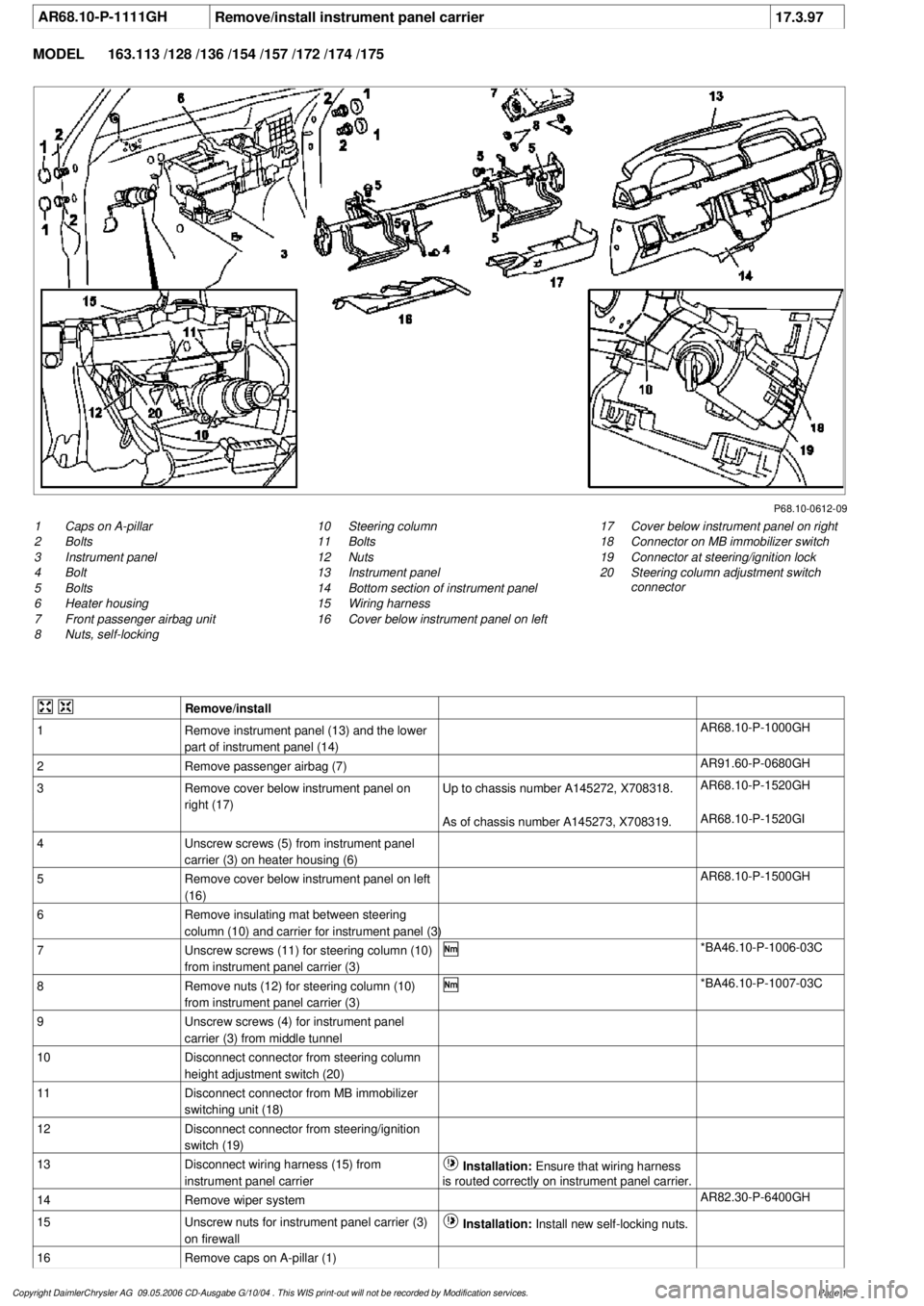
P68.10-0612-09
1
Caps on A-pillar
2
Bolts
3
Instrument panel
4
Bolt
5
Bolts
6
Heater housing
7
Front passenger airbag unit
8
Nuts, self-locking
17
Cover below instrument panel on right
18
Connector on MB immobilizer switch
19
Connector at steering/ignition lock
20
Steering column adjustment switch
connector
10
Steering column
11
Bolts
12
Nuts
13
Instrument panel
14
Bottom section of instrument panel
15
Wiring harness
16
Cover below instrument panel on left
Remove/install
1
Remove instrument panel (13) and the lower
part of instrument panel (14)
AR68.10-P-1000GH
2
Remove passenger airbag (7)
AR91.60-P-0680GH
3
Remove cover below instrument panel on
right (17)
Up to chassis number A145272, X708318.
AR68.10-P-1520GH
As of chassis number A145273, X708319.
AR68.10-P-1520GI
4
Unscrew screws (5) from instrument panel
carrier (3) on heater housing (6)
5
Remove cover below instrument panel on left
(16)
AR68.10-P-1500GH
6
Remove insulating mat between steering
column (10) and carrier for instrument panel (3)
7
Unscrew screws (11) for steering column (10)
from instrument panel carrier (3)
*BA46.10-P-1006-03C
8
Remove nuts (12) for steering column (10)
from instrument panel carrier (3)
*BA46.10-P-1007-03C
9
Unscrew screws (4) for instrument panel
carrier (3) from middle tunnel
10
Disconnect connector from steering column
height adjustment switch (20)
11
Disconnect connector from MB immobilizer
switching unit (18)
12
Disconnect connector from steering/ignition
switch (19)
13
Disconnect wiring harness (15) from
instrument panel carrier
Installation:
Ensure that wiring harness
is routed correctly on instrument panel carrier.
14
Remove wiper system
AR82.30-P-6400GH
15
Unscrew nuts for instrument panel carrier (3)
on firewall
Installation:
Install new self-locking nuts.
16
Remove caps on A-pillar (1)
Copyright DaimlerChrysler AG 09.05.2006 CD-Ausgabe G/10/04 . This WIS print-out will not be recorde
d by Modification services.
Page 1
Page 3542 of 4133

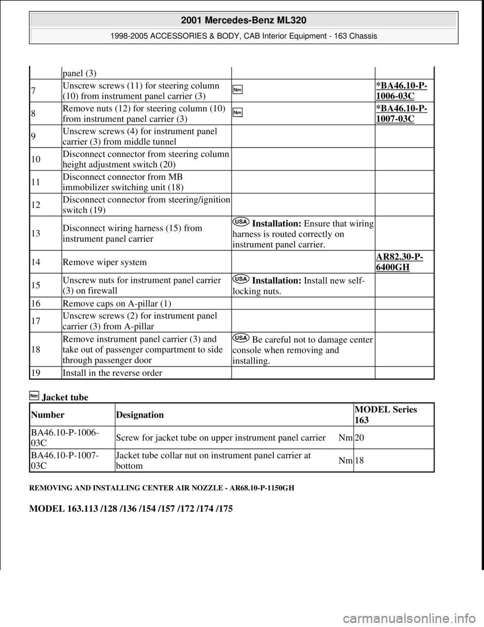
Jacket tube
REMOVING AND INSTALLING CENTER AIR NOZZLE - AR68.10-P-1150GH
MODEL 163.113 /128 /136 /154 /157 /172 /174 /175
panel (3)
7Unscrew screws (11) for steering column
(10) from instrument panel carrier (3) *BA46.10-P-
1006-03C
8Remove nuts (12) for steering column (10)
from instrument panel carrier (3) *BA46.10-P-
1007-03C
9Unscrew screws (4) for instrument panel
carrier (3) from middle tunnel
10Disconnect connector from steering column
height adjustment switch (20)
11Disconnect connector from MB
immobilizer switching unit (18)
12Disconnect connector from steering/ignition
switch (19)
13Disconnect wiring harness (15) from
instrument panel carrier Installation:Ensure that wiring
harness is routed correctly on
instrument panel carrier.
14Remove wiper system AR82.30-P-
6400GH
15Unscrew nuts for instrument panel carrier
(3) on firewall Installation: Install new self-
locking nuts.
16Remove caps on A-pillar (1)
17Unscrew screws (2) for instrument panel
carrier (3) from A-pillar
18
Remove instrument panel carrier (3) and
take out of passenger compartment to side
through passenger doorBe careful not to damage center
console when removing and
installing.
19Install in the reverse order
NumberDesignationMODEL Series
163
BA46.10-P-1006-
03CScrew for jacket tube on upper instrument panel carrierNm20
BA46.10-P-1007-
03CJacket tube collar nut on instrument panel carrier at
bottomNm18
2001 Mercedes-Benz ML320
1998-2005 ACCESSORIES & BODY, CAB Interior Equipment - 163 Chassis
me
Saturday, October 02, 2010 3:35:21 PMPage 24 © 2006 Mitchell Repair Information Company, LLC.