1997 MERCEDES-BENZ ML350 boot
[x] Cancel search: bootPage 2575 of 4133
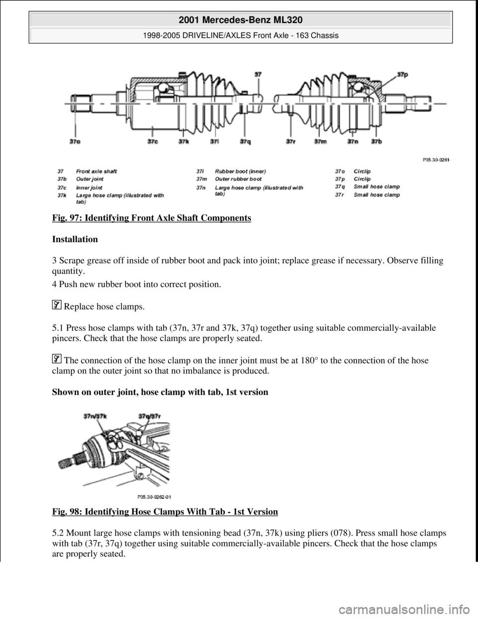
Fig. 97: Identifying Front Axle Shaft Components
Installation
3 Scrape grease off inside of rubber boot and pack into joint; replace grease if necessary. Observe filling
quantity.
4 Push new rubber boot into correct position.
Replace hose clamps.
5.1 Press hose clamps with tab (37n, 37r and 37k, 37q) together using suitable commercially-available
pincers. Check that the hose clamps are properly seated.
The connection of the hose clamp on the inner joint must be at 180° to the connection of the hose
clamp on the outer joint so that no imbalance is produced.
Shown on outer joint, hose clamp with tab, 1st version
Fig. 98: Identifying Hose Clamps With Tab
- 1st Version
5.2 Mount large hose clamps with tensioning bead (37n, 37k) using pliers (078). Press small hose clamps
with tab (37r, 37q) together using suitable commercially-available pincers. Check that the hose clamps
are properly seated.
2001 Mercedes-Benz ML320
1998-2005 DRIVELINE/AXLES Front Axle - 163 Chassis
me
Saturday, October 02, 2010 3:38:22 PMPage 56 © 2006 Mitchell Repair Information Company, LLC.
Page 2577 of 4133
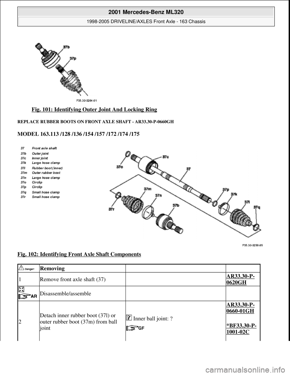
Fig. 101: Identifying Oute r Joint And Locking Ring
REPLACE RUBBER BOOTS ON FRONT AXLE SHAFT - AR33.30-P-0660GH
MODEL 163.113 /128 /136 /154 /157 /172 /174 /175
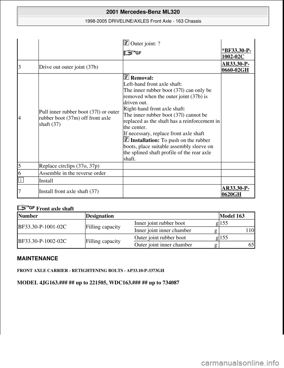
Fig. 102: Identifying Fron t Axle Shaft Components
Removing
1Remove front axle shaft (37) AR33.30-P-
0620GH
Disassemble/assemble
2
Detach inner rubber boot (37l) or
outer rubber boot (37m) from ball
joint
AR33.30-P-
0660-01GH
Inner ball joint: ?
*BF33.30-P-
1001-02C
2001 Mercedes-Benz ML320
1998-2005 DRIVELINE/AXLES Front Axle - 163 Chassis
me
Saturday, October 02, 2010 3:38:22 PMPage 58 © 2006 Mitchell Repair Information Company, LLC.
Page 2578 of 4133
Front axle shaft
MAINTENANCE
FRONT AXLE CARRIER - RETIGHTENING BOLTS - AP33.10-P-3373GH
MODEL 4JG163.### ## up to 221505, WDC163.### ## up to 734087
Outer joint: ?
*BF33.30-P-
1002-02C
3Drive out outer joint (37b) AR33.30-P-
0660-02GH
4
Pull inner rubber boot (37l) or outer
rubber boot (37m) off front axle
shaft (37)
Removal:
Left-hand front axle shaft:
The inner rubber boot (37l) can only be
removed when the outer joint (37b) is
driven out.
Right-hand front axle shaft:
The inner rubber boot (37l) cannot be
replaced as the shaft has a reinforcement in
the center.
If necessary, replace front axle shaft
Installation: To push on the rubber
boots, place suitable assembly sleeve on
the splined shaft profile of the rear axle
shaft.
5Replace circlips (37o, 37p)
6Assemble in the reverse order
Install
7Install front axle shaft (37) AR33.30-P-
0620GH
NumberDesignationModel 163
BF33.30-P-1001-02CFilling capacityInner joint rubber bootg155
Inner joint inner chamberg110
BF33.30-P-1002-02CFilling capacityOuter joint rubber bootg155
Outer joint inner chamberg65
2001 Mercedes-Benz ML320
1998-2005 DRIVELINE/AXLES Front Axle - 163 Chassis
me
Saturday, October 02, 2010 3:38:22 PMPage 59 © 2006 Mitchell Repair Information Company, LLC.
Page 2579 of 4133
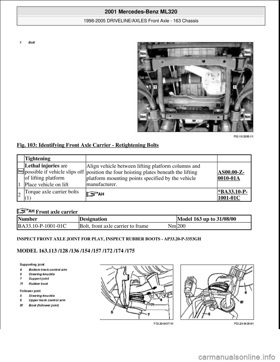
Fig. 103: Identifying Front Axle Carrier - Retightening Bolts
Front axle carrier
INSPECT FRONT AXLE JOINT FOR PLAY, INSPECT RUBBER BOOTS - AP33.20-P-3353GH
MODEL 163.113 /128 /136 /154 /157 /172 /174 /175
Tightening
Lethal injuries are
possible if vehicle slips off
of lifting platformAlign vehicle between lifting platform columns and
position the four hoisting plates beneath the lifting
platform mounting points specified by the vehicle
manufacturer.
AS00.00-Z-
0010-01A
1Place vehicle on lift
2Torque axle carrier bolts
(1) *BA33.10-P-
1001-01C
NumberDesignationModel 163 up to 31/08/00
BA33.10-P-1001-01CBolt, front axle carrier to frameNm200
2001 Mercedes-Benz ML320
1998-2005 DRIVELINE/AXLES Front Axle - 163 Chassis
me
Saturday, October 02, 2010 3:38:22 PMPage 60 © 2006 Mitchell Repair Information Company, LLC.
Page 2580 of 4133
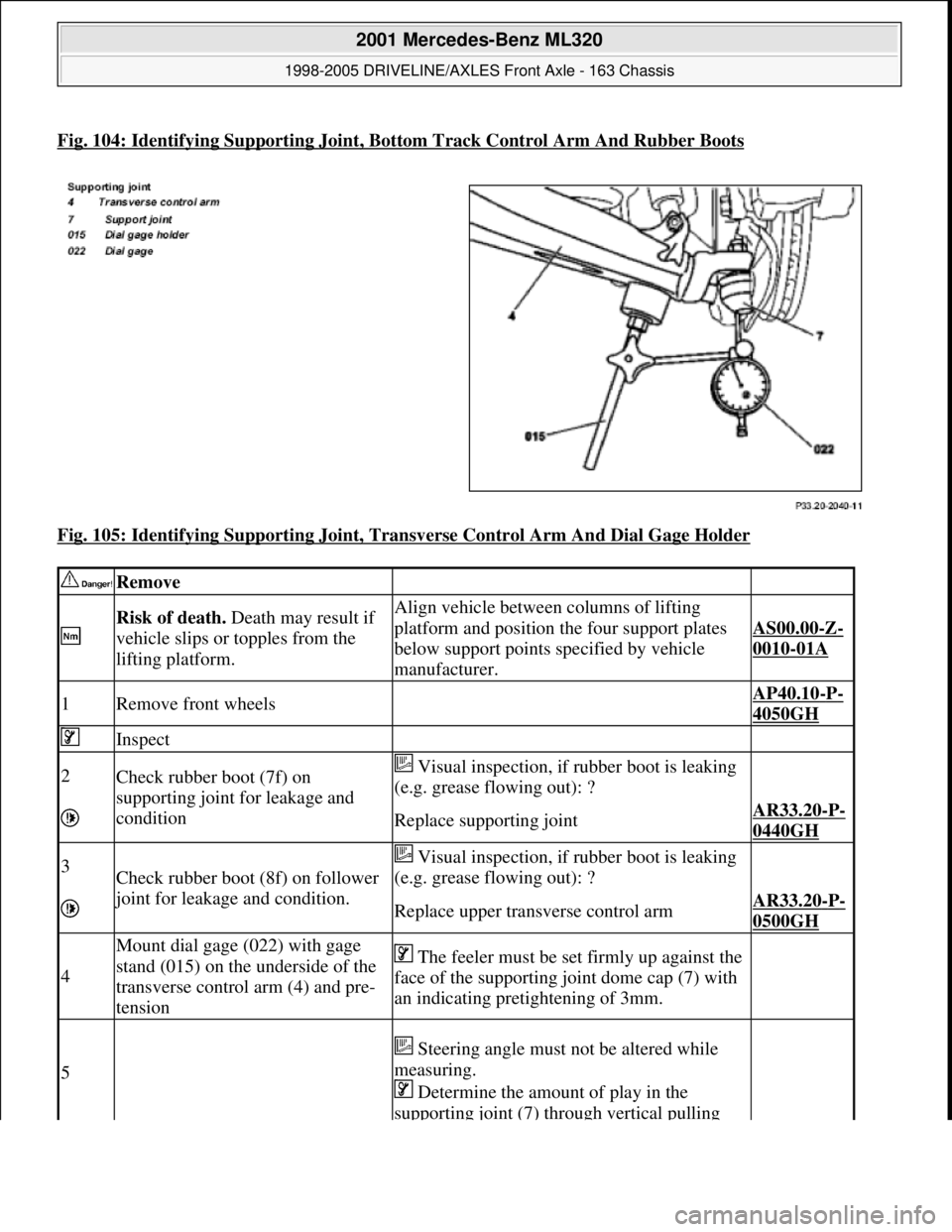
Fig. 104: Identifying Supporting Joint, Bottom Track Control Arm And Rubber Boots
Fig. 105: Identifying Supporting Joint, Transverse Control Arm And Dial Gage Holder
Remove
Risk of death. Death may result if
vehicle slips or topples from the
lifting platform.Align vehicle between columns of lifting
platform and position the four support plates
below support points specified by vehicle
manufacturer.
AS00.00-Z-
0010-01A
1Remove front wheels AP40.10-P-
4050GH
Inspect
2Check rubber boot (7f) on
supporting joint for leakage and
condition Visual inspection, if rubber boot is leaking
(e.g. grease flowing out): ?
Replace supporting jointAR33.20-P-
0440GH
3Check rubber boot (8f) on follower
joint for leakage and condition.
Visual inspection, if rubber boot is leaking
(e.g. grease flowing out): ?
Replace upper transverse control armAR33.20-P-
0500GH
4
Mount dial gage (022) with gage
stand (015) on the underside of the
transverse control arm (4) and pre-
tension The feeler must be set firmly up against the
face of the supporting joint dome cap (7) with
an indicating pretightening of 3mm.
5
Steering angle must not be altered while
measuring.
Determine the amount of play in the
supporting joint (7) through vertical pulling
2001 Mercedes-Benz ML320
1998-2005 DRIVELINE/AXLES Front Axle - 163 Chassis
me
Saturday, October 02, 2010 3:38:22 PMPage 61 © 2006 Mitchell Repair Information Company, LLC.
Page 2609 of 4133

Remove, Install
Danger!
Risk of explosion
from fuel igniting,
risk of
poisoning
from inhaling and swallowing fuel
as well as
risk of injury
to eyes and skin
from contact with fuel.
Fire, sparks, open flames or smoking
forbidden.
Pour fuels only into suitable and appropriately
marked containers.
Wear protective clothing when handling fuel.
AS47.00-Z-0001-01A
1
Drain fuel tank
Via fuel pump. NOT for model 163.113/128.
AR47.10-P-4001GH
If fuel pump faulty, and model 163.113/128.
AR47.10-P-4000GH
*BF47.10-P-1001-01A
2
Unscrew filler cap (2) and detach from filler
cap attachment (4)
3.1
Remove left seat of 3rd seat row
If installed. See owner's manual
4
Unclip cover of left-hand side panel (1)
5.1
Detach fuel lines of expansion reservoir and
separate from filler neck
As of VIN A289565. NOT for model
163.113/128.
6
Detach fuel filler neck from guide funnel
Installation:
Check O-ring and replace if
necessary. Ensure that the bayonet-lock
remains above
the pressure sensor.
Ensure it is correctly located when installed.
Open bayonet lock (3) to do this.
7
Pull filler neck through toward interior
Screw on cap again in order to avoid fuel
flowing out.
8.1
Remove fuel tank pressure sensor (B4/3)
Only USA version
AR47.10-P-8022GH
9.1
Detach bolted connection of fuel tank filler
neck/ground (X36/4) from filler neck
NOT for model 163.113/128.
10.1
Cut cable strap for retaining clips of fuel lines
at filler neck and remove retaining clips
As of VIN A289565. NOT for model
163.113/128.
Danger!
Risk of fatal accident
from vehicle slipping
or toppling off the lift platform
Align vehicle between the columns of lifting
platform and position the four support plates
below the support strongpoints specified by
the vehicle manufacturer.
AS00.00-Z-0010-01A
11
Place the vehicle on lifting platform
AR00.60-P-1000GH
12
Separate rubber seal (5) from underside of
vehicle and remove filler neck from interior
Do not damage fuel lines at filler neck.
13
Remove left rear wheel
e
Removing and installing wheels, rotating if
necessary
AP40.10-P-4050GH
14
Remove spare wheel and spare wheel carrier
complete
NOT in the case of spare wheel
holder/spare wheel, code 849.
15
Cut a large safety cable strap for filler neck at
bracket on longitudinal frame member
16
Remove bracket from longitudinal frame
member
17
Disconnect connection for regeneration (77/2)
and fresh air connection (77/4) on activated
charcoal canister (77)
Installation
: Connect up lines as per
connection diagram:
#
Engine 111
AR47.30-P-8212-01GJ
Engines 112, 113
AR47.30-P-8212-01GI
Engines 112, 113 version
I
AR47.30-P-8212-01GH
Charcoal canister and fuel tank form a
single unit.
NOT for model 163.113/128.
18
Detach vent hose
At rear differential to rear of activated
charcoal reservoir.
19
Remove rear exhaust system heat shield.
Do not damage boot at rear axle shaft.
20
Disconnect rear propeller shaft at differential
Installation:
Install new self-locking bolts.
Tie up propeller shaft e.g. using welding
wire
Heat bolts with hot air fan to facilitate
removing. Mark propeller shaft and differential
gear flange for correct installed position.
*BA41.10-P-1002-01C
Copyright DaimlerChrysler AG 28.05.2006 CD-Ausgabe G/10/04 . This WIS print-out will not be recorde
d by Modification services.
Page 2
Page 3049 of 4133
CHECK ALL VISIBLE PARTS FOR SIGNS OF LEAKS AND DAMAGE - AP00.20-P-0053GH
MODEL 163.113 /128 /136 /154 /157 /172 /174 /175
INSPECTING CHASSIS AND LOAD-BEARING BODY PARTS FOR DAMAGE AND CORROSION - AP00.20-P-0090GH
MODEL 163
with Code Z04/Z07
Model 230AP00.20-P-0001L
Model 414AP00.20-L-0001A
Taxi serviceModels 202, 210AP00.20-P-0007A
Model 203AP00.20-P-0007C
Remove
Detach lower engine
compartment panelingModels 163.172/174/175AR61.20-P-1105GH
Remove noise
encapsulationModel 163.113/128AR94.30-P-5400GH
Check
2If traces of fluid are noted
(e.g. oil), then determine
and correct the cause (on a
separate work order).
Check for leaksEngine:
Transmission
Transfer case
Front axle
Rear axle
Pressure oil pump
3Check for leaks and fixingShock absorbers,
suspension struts
4Inspect for leaks and
conditionRubber boots of front axle
shafts
5Inspect lines and hoses for
leaks and condition, pay
attention to chafing points
and routingRadiator
Fuel system
Exhaust system
Clutch actuation
Automatic transmission
Power steering
Brake system
Install
Install lower engine
compartment paneling.Models 163.172/174/175AR61.20-P-1105GH
Install noise encapsulationModel 163.113/128AR94.30-P-5400GH
1Visual inspectionControl arm mountings and
control arms of front axle
2004 Mercedes-Benz ML350
1998-2005 GENINFO Overall vehicle - 163 Chassis
me
Saturday, October 02, 2010 3:47:52 PMPage 404 © 2006 Mitchell Repair Information Company, LLC.
Page 3175 of 4133
GENERAL BRAKE FLUID - BB00.40-P-0330-01A
These specifications are valid for the Mercedes-Benz and smart brands.
General
The brake fluid in the brake system and in the hydraulic clutch operating system fulfills hydraulic tasks. Due to
the high heat build-up during braking, these tasks can only be fulfilled by brake fluids which comply with all of
today's technical requirements in terms of their various properties (viscosity-temperature-characteristic, boiling
point, corrosion protection, oxidation resistance, etc.).
The most important properties which a brake fluid must exhibit are:
High boiling point, to ensure that the brake fluid does not form vapor locks at high temperatures. Vapor
locks reduce the operating pressure and thus the braking effect and may ultimately lead to brake failure.
The boiling point should remain as constant as possible throughout the duration of use of the coolant and
not drop under varying atmospheric influences or operating conditions (pressure, temperature), i.e. the
"wet boiling point" should be as high as possible.
Low compressibility, in particular at high temperatures.
The low-temperature characteristic of the fluid - even when at 40°C - must permit operation, i.e.
primarily, the viscosity must not become too high in the cold.
Compatibility with the materials used in the brake units and clutch operating systems, e.g. the rubber
boots or any other seal materials (elastomers) included in the brake components may only swell to a
controlled extent, any shrinkage must be avoided.
Sufficient corrosion protection for all metals present in the brake system.
The brake fluids released for use in MB vehicle models are listed on Sheet 331.0. These brake fluids not only
comply with our requirements, but also those of the US safety specifications FMVSS 116, DOT 4. The released
"DOT 4 plus" brake fluids (internal designation) are more advanced DOT 4 brake fluids with higher wet boiling
point, standard change interval: 2 years. In order to be able to comply with this useful period without any
problem, we strongly advise the use of released products as per Sheet 331.0, during the warranty phase this is a
precondition for any acceptance of customer claims.
The brake fluid listed on Sheet 331.1 "DOT 4 Type 200" is released for special applications in the UNIMOG
range with more stringent thermal requirements. For this type of use, a brake fluid change interval of 1 year
must be adhered to.
Handling brake fluid
Brake fluid based on polyhydric alcohols in oligomer or polymer form and/or their
Esters are hygroscopic and thus absorbs moisture from the air. Water, however, reduces the boiling point of the
brake fluid, whereby the danger of vapor lock formation is present. Therefore it should be noted that brake fluid
is always stored in sealed vessels. Brake fluid that has been stored unsealed can absorb so much moisture in a
few hours that it is rendered unusable.
2004 Mercedes-Benz ML350
1998-2005 GENINFO Overall vehicle - 163 Chassis
me
Saturday, October 02, 2010 3:47:57 PMPage 530 © 2006 Mitchell Repair Information Company, LLC.