1997 MERCEDES-BENZ ML350 manual transmission
[x] Cancel search: manual transmissionPage 3226 of 4133
A/C EVAPORATOR HOUSING UNIT
Removal & Installation
1. Drain engine coolant. Remove coolant expansion reservoir nuts, disconnect hoses and remove reservoir.
Discharge A/C system, using approved refrigerant recovery/recycling equipment.
2. Remove expansion valve self-locking nut and discard. See Fig. 5
. Disconnect refrigerant lines from
expansion valve. Plug exposed refrigerant lines to protect A/C system from moisture and debris.
3. Remove instrument panel. See INSTRUMENT PANEL
. Remove Electronic Transmission Control
(ETC) module. See Fig. 4
. Disconnect air mix flap actuator connector.
4. Disconnect recirculated air flap element. Disconnect evaporator temperature sensor. Disconnect blower
motor resistor and blower motor connectors. Remove A/C push button control module. Release wiring
harness.
5. Remove insulating mat. See Fig. 5
. Disconnect water drain hose from bottom of A/C housing. Release
A/C housing-to-air distributor clips and remove A/C housing upward. To install, reverse removal
procedure. Recode radio. See RECODING RADIO
under PROGRAMMING. WARNING:To avoid injury from accidental air bag deployment, read and carefully
follow all SERVICE PRECAUTIONS and DISABLING & ACTIVATING AIR
BAG SYSTEM procedures in AIR BAG SYSTEM SAFETY article in
GENERAL SERVICING.
CAUTION: Before disconnecting battery, obtain 5-digit radio security code from
vehicle owner. Radio will be disabled until properly recoded.
2001 Mercedes-Benz ML320
2000-01 MANUAL A/C-HEATER SYSTEMS ML 320, ML 430 & ML 55
me
Saturday, October 02, 2010 3:25:10 PMPage 15 © 2006 Mitchell Repair Information Company, LLC.
Page 3232 of 4133
Fig. 6: Removing Cooling Fans & Condenser
Courtesy of MERCEDES-BENZ OF NORTH AMERICA.
COOLING FANS
Removal & Installation
Remove headlight units. Remove upper frame crossmember, release hood release control cable and remove
crossmember. See Fig. 6
. Remove 2 cooling fans frame bolts on radiator. Disconnect cooling fan connector.
Release outside temperature sensor wiring harness. Pull up on cooling fan and remove. To install, reverse
removal procedure. Ensure cooling fan bottom guides are properly seated in lower mounts.
EVAPORATOR
Removal & Installation
Remove A/C housing unit. See A/C HOUSING UNIT . Remove expansion valve. See Fig. 5 . Discard "O"
rings. Disassemble A/C housing unit. Remove evaporator. Remove evaporator temperature sensor. To install,
reverse removal procedure. Use NEW "O" rings lubricated with refrigerant oil. If installing a new or repair
evaporator, add 1.35 ounces of NEW refrigerant oil to evaporator.
EXPANSION VALVE
Removal & Installation
1. Discharge A/C system, using approved refrigerant recovery/recycling equipment. Without disconnecting
coolant hoses, remove coolant expansion reservoir and set aside. Remove refrigerant line bracket and
loosen clamps. See Fig. 5
. Pull refrigerant lines out of expansion valve.
2. Remove expansion valve self-locking nut and discard. Remove expansion valve. Discard "O" rings. To
install, reverse removal procedure. Use NEW "O" rings lubricated with refrigerant oil. Tighten NEW self-
locking nut to specification. See TORQUE SPECIFICATIONS
.
INSTRUMENT PANEL & INSTRUMENT PANEL CARRIER
Removal & Installation
1. Secure vehicle against rolling. Set transmission selector to "D" position. Obtain radio security code.
Disconnect negative battery cable. Remove driver-side air bag.
2. Place match marks on steering wheel and steering shaft. Remove steering wheel, upper steering column
covers and combination switch. Remove instrument cluster cover frame. Remove one instrument panel
lower section bolt.
3. Remove screws in footwell from left side of instrument panel bottom section. Remove instrument panel
center section. Remove 4 A/C control panel screws and remove control panel. See Fig. 1
. Release pull
cables and disconnect connectors.
4. Remove screws from center section. Remove glove box. Remove screws in footwell from right side of
instrument panel bottom section. Remove entry courtesy lights. Remove end covers and screws.
5. Release 4 "A" clips between instrument panel bottom section and upper section. See Fig. 7
. Release
parkin
g brake release cable from handle. With assistance, remove instrument panel bottom section.
2001 Mercedes-Benz ML320
2000-01 MANUAL A/C-HEATER SYSTEMS ML 320, ML 430 & ML 55
me
Saturday, October 02, 2010 3:25:10 PMPage 21 © 2006 Mitchell Repair Information Company, LLC.
Page 3745 of 4133

2.1
Detach automatic transmission from engine
Models 463.206/ 209/ 232/ 233/ 240/ 241
AR27.10-P-0500BD
Models 463.243/ 244/ 245/ 246/ 247/ 248/
249/ 250/ 254
AR27.10-P-0500GA
Model 230.475
AR27.10-P-0500R
Model 230.474
Model 220 without 4MATIC
AR27.10-P-0500I
Model 220 with 4MATIC
AR27.10-P-0500IW
Models 129, 170, 202, 208, 210
AR27.10-P-0500B
Model 203 without 4MATIC, 209 with Engine
112,113
AR27.10-P-0500P
Model 203 with 4MATIC
AR27.10-P-0500PW
Model 211.061/065/070
AR27.10-P-0500T
Model 163
AR27.10-P-0500GH
2.2
Detach manual transmission from engine
Models 129, 202, 210
AR26.10-P-0020A
Models 203, 209 with Engine 112
AR26.10-P-0020P
Model 211.061
AR26.10-P-0020T
Model 208 with transmission 716.662/622
AR26.10-P-0020E
Model 170,
Model 208 with transmission 716.663
AR26.10-P-0020D
3
Detach top part of oil pan
Models 463.206/ 209/ 232/ 233/ 240/ 241/
243/ 244/ 245/ 246/ 247/ 248/ 249/ 250/ 254
AR01.45-P-7500FG
Model 230.474/
AR01.45-P-7500R
Model 220 without 4MATIC
AR01.45-P-7500I
Model 220 with 4MATIC
AR01.45-P-7500IW
Model 210 with 4MATIC
AR01.45-P-7500FA
Model 210 without 4MATIC
AR01.45-P-7500F
Models 202, 208
AR01.45-P-7500FC
Model 203 without 4MATIC, 209 with Engine
112,113
AR01.45-P-7500PV
Model 203 with 4MATIC
AR01.45-P-7500PW
Models 211.061/065/070
AR01.45-P-7500TV
Model 170
AR01.45-P-7500SV
Model 163
AR01.45-P-7500FB
Model 129
AR01.45-P-7500FD
4
Take off cylinder head
Remove intake manifold with complete
wiring loom during this step.
Models 463.206/ 209/ 232/ 233/ 240/ 241/
243/ 244/ 245/ 246/ 247/ 248/ 249/ 250/ 254
AR01.30-P-5800GV
Engine 112 in model 129 and engine 113 in
models 129, 202, 208, 210
AR01.30-P-5800B
Engine 112 in models 170, 202, 208, 210,
220 and engine 113 in models 220,
230.474 /475
AR01.30-P-5800BA
Model 163
AR01.30-P-5800MV
Models 203, 209 with engine 112, 113
Models 211.061/065/070
AR01.30-P-5800PV
5
Remove oil pump
Push back chain tensioner for this step
and take off chain.
All except models 203, 209, 211.061/065/070,
220 without 4MATIC, 230.474 /475
AR18.10-P-6020B
Model 203 without 4MATIC, 209,
211.061/065/070
AR18.10-P-6020PV
Model 203 with 4MATIC, model 220 with
4MATIC
AR18.10-P-6020PW
Model 230.474/475
AR18.10-P-6020R
6
Remove conrod bearing cap (5)
For this step, mark conrod (4) and
connecting rod bearing cap (5) on one side
relative to each other.
7
Remove conrod (4) together with pistons (3)
by lifting up and out
If pistons have been used (3), the arrows
indicating the direction of the travel and the
markings on the pistons may no longer be
visible due to carbon deposits. For this
reason, remove the carbon deposits from the
pistons. If the arrows indicating direction of
travel on the pistons are no longer
recognizable, these must be re-marked.
8
Remove circlip (1) of piston pin (2)
Do not damage piston (3). Place a clean
cloth underneath.
9
Press out piston pin (2)
Installing
10
Assign piston (3) to cylinder bore
AR03.10-P-7021-02BV
Copyright DaimlerChrysler AG 20.05.2006 CD-Ausgabe G/10/04 . This WIS print-out will not be recorde
d by Modification services.
Page 2
Page 3747 of 4133

25.1
Fit on automatic transmission
Models 463.206/ 209/ 232/ 233/ 240/ 241
AR27.10-P-0500BD
Models 463.243/ 244/ 245/ 246/ 247/ 248/
249/ 250/ 254
AR27.10-P-0500GA
Model 230.475
AR27.10-P-0500R
Model 230.474
Model 220 without 4MATIC
AR27.10-P-0500I
Model 220 with 4MATIC
AR27.10-P-0500IW
Models 210, 208, 202,170. 129
AR27.10-P-0500B
Model 203 without 4MATIC, 209 with engines
112,113
AR27.10-P-0500P
Model 203 with 4MATIC
AR27.10-P-0500PW
Models 211.061/065/070
AR27.10-P-0500T
Model 163
AR27.10-P-0500GH
25.2
Fit on manual transmission
Models 210, 202, 129
AR26.10-P-0020A
Models 203, 209 with engine 112
AR26.10-P-0020P
Model 211.061
AR26.10-P-0020T
Model 208 with transmissions 716.662/622
AR26.10-P-0020E
Model 170,
Model 208 with transmission 716.663
AR26.10-P-0020D
26
Install engine
Models 463.243/ 244/ 245/ 246/ 247/ 248/
249/ 250/ 254
AR01.10-P-2400CC
Model 230.475
AR01.10-P-2400R
Model 230.474
AR01.10-P-2400RVK
Model 220 without 4MATIC
AR01.10-P-2400AB
Model 220 with 4MATIC
AR01.10-P-2400IW
Model 210 with 4MATIC
AR01.10-P-2400C
Model 210 without 4MATIC, 208, 202, 129
AR01.10-P-2400CB
Model 203 without 4MATIC, 209 with engine
112
AR01.10-P-2400PV
Model 203 with 4MATIC
AR01.10-P-2400PW
Model 209 with engine 113
AR01.10-P-2400Q
Models 211.061/065/070
AR01.10-P-2400TC
Model 170
AR01.10-P-2400SV
Model 163
AR01.10-P-2400CA
Inspection data of conrod bolts
Number
Designation
Engine
112 except
112.951,
113.94/96/980/
981/982/984/986
Engine
113.992
BE03.10-P-1001-03A
Conrod bolts
Thread
4M8B18B1
Shank length
when new
mm
4742
max.
mm
47.642.6
Part no.
--
Designation
Engines
112 except
112.951,
113.940/941/
942/943/944/
945/946/948/
960/961/962/
963/965/966/
967/968/980/
981/982/984/
986/987/988/
990/991/992/
993
BA03.10-P-1001-01E
Connecting rod bolt
Stage 1
Nm
5
2nd stage
Nm
25
Copyright DaimlerChrysler AG 20.05.2006 CD-Ausgabe G/10/04 . This WIS print-out will not be recorde
d by Modification services.
Page 4
Page 3852 of 4133
ENGINE 119.980 /981 /982 /985
ENGINE 120.982/983
ENGINE 137.970
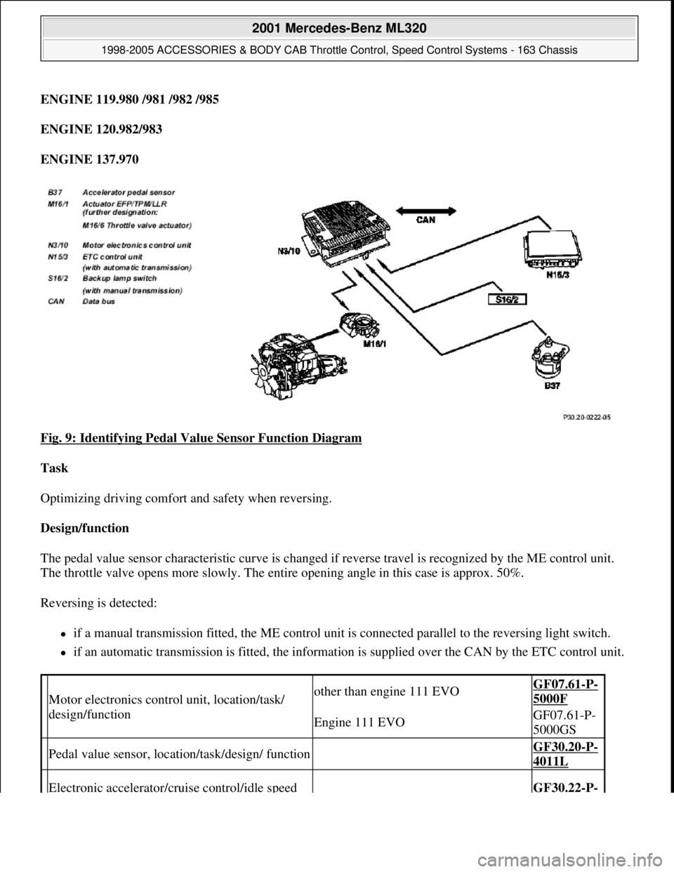
Fig. 9: Identifying Pedal Value Sensor Function Diagram
Task
Optimizing driving comfort and safety when reversing.
Design/function
The pedal value sensor characteristic curve is changed if reverse travel is recognized by the ME control unit.
The throttle valve opens more slowly. The entire opening angle in this case is approx. 50%.
Reversing is detected:
if a manual transmission fitted, the ME control unit is connected parallel to the reversing light switch.
if an automatic transmission is fitted, the information is supplied over the CAN by the ETC control unit.
Motor electronics control unit, location/task/
design/functionother than engine 111 EVOGF07.61-P-
5000F
Engine 111 EVOGF07.61-P-
5000GS
Pedal value sensor, location/task/design/ function GF30.20-P-
4011L
Electronic accelerator/cruise control/idle speed GF30.22-P-
2001 Mercedes-Benz ML320
1998-2005 ACCESSORIES & BODY CAB Throttle Control, Speed Control Systems - 163 Chassis
me
Saturday, October 02, 2010 3:36:27 PMPage 12 © 2006 Mitchell Repair Information Company, LLC.
Page 3867 of 4133
Vehicles with EZS control unit without column sleeve module (MRM)
The signals from the push-button switch for the cruise control are detected by the control unit EIS and
transmitted to the CAN data bus.
Vehicles without EZS control unit
The signals from the cruise control switch are transmitted directly to the engine control unit.
Vehicles with manual transmission (MT)
Cruise control remains active during gear change, in other words the cruise control is not switched off when the
clutch is operated.
Traction systems control unit
Transmits the vehicle speed signal via CAN to the ME control unit.
CRUISE CONTROL SWITCH, LOCATION/TASK/DESIGN/FUNCTION - GF30.30-P-3100F
ENGINE 104 (except 104.98),
Motor electronics control unit, location/task/
design/functionother than engine 111 EVOGF07.61-P-
5000F
Engine 111 EVOGF07.61-P-
5000GS
Cruise control switch, location/task/design/
functionwith cruise control or Distronic GF30.30-P-
3100F
Variable cruise control switch, location/task/
design/functionwith cruise control or Distronic except
GF30.30-P-
3101A
Electronic accelerator/cruise control/idle speed
control actuator location/task/design/function GF30.22-P-
4010F
Throttle valve actuator, location/task/design/
functionEngine 111 EVOGF30.22-P-
4101GS
Stop lamp switch, location/task/function GF42.10-P-
4000A
Clutch pedal switch, location/task/functionwith MTGF29.10-P-
2100F
Variable speed limiter, functionAdditional cruise control function except
GF30.30-P-
3001A
ETC control unit, location/task
Transmits information about the selector
lever position P/N and the driving mode
selected via CAN.
Transmission 722.6
GF27.19-P-
4012G
2001 Mercedes-Benz ML320
1998-2005 ACCESSORIES & BODY CAB Throttle Control, Speed Control Systems - 163 Chassis
me
Saturday, October 02, 2010 3:36:27 PMPage 27 © 2006 Mitchell Repair Information Company, LLC.
Page 3874 of 4133
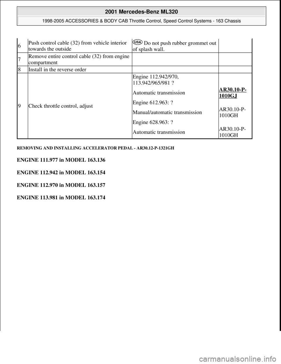
REMOVING AND INSTALLING ACCELERATOR PEDAL - AR30.12-P-1321GH
ENGINE 111.977 in MODEL 163.136
ENGINE 112.942 in MODEL 163.154
ENGINE 112.970 in MODEL 163.157
ENGINE 113.981 in MODEL 163.174
6Push control cable (32) from vehicle interior
towards the outside Do not push rubber grommet out
of splash wall.
7Remove entire control cable (32) from engine
compartment
8Install in the reverse order
9Check throttle control, adjust
Engine 112.942/970,
113.942/965/981 ?
Automatic transmissionAR30.10-P-
1010GJ
Engine 612.963: ?
Manual/automatic transmissionAR30.10-P-
1010GH
Engine 628.963: ?
Automatic transmissionAR30.10-P-
1010GH
2001 Mercedes-Benz ML320
1998-2005 ACCESSORIES & BODY CAB Throttle Control, Speed Control Systems - 163 Chassis
me
Saturday, October 02, 2010 3:36:28 PMPage 34 © 2006 Mitchell Repair Information Company, LLC.
Page 3891 of 4133
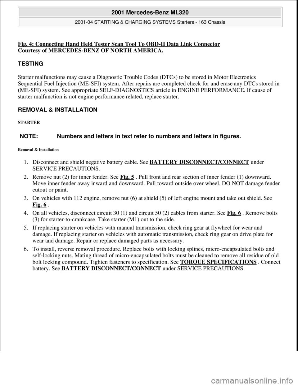
Fig. 4: Connecting Hand Held Tester Scan Tool To OBD-II Data Link Connector
Courtesy of MERCEDES-BENZ OF NORTH AMERICA.
TESTING
Starter malfunctions may cause a Di agnostic Trouble Codes (DTCs) to be stored in Motor Electronics
Sequential Fuel Injection (ME-SFI) sy stem. After repairs are completed check for and erase any DTCs stored in
(ME-SFI) system. See appropriate SE LF-DIAGNOSTICS article in ENGINE PERFORMANCE. If cause of
starter malfunction is not engine pe rformance related, replace starter.
REMOVAL & INSTALLATION
STARTER
Removal & Installation
1. Disconnect and shield negative battery cable. See BATTERY DISCONNECT/CONNECT under
SERVICE PRECAUTIONS.
2. Remove nut (2) for inner fender. See Fig. 5
. Pull front and rear section of inner fender (1) downward.
Move inner fender away inward and downward. Pull toward outside over wheel. DO NOT damage fender
cutout or paint.
3. On vehicles with 112 engine, remove nut (6) at shield (5) of left engine mount and take out shield. See
Fig. 6
.
4. On all vehicles, disconnect circuit 30 (1) and circuit 50 (2) cables from starter. See Fig. 6
. Remove bolts
(3) for starter-to-crankcase. Take starter (M1) out to the side.
5. If replacing starter on vehicles with manual transmission, check ring gear at flywheel for wear and
damage. If replacing starter on vehicles with auto matic transmission, check ring gear on drive plate for
wear and damage. Repair or repl ace damaged parts as necessary.
6. To install, reverse removal proce dure. Replace bolts with locking splines, micro-encapsulated bolts and
self-locking nuts. Mating thread of mi cro-encapsulated bolts must be cleaned to remove all residue of old
bolt locking compound. Tighten fasteners to specification. See TORQUE SPECIFICATIONS
. Connect
battery. See BATTERY DISCONNECT/CONNECTunder SERVICE PRECAUTIONS.
NOTE: Numbers and letters in text refe
r to numbers and letters in figures.
2001 Mercedes-Benz ML320
2001-04 STARTING & CHARGING SYSTEMS Starters - 163 Chassis
me
Saturday, October 02, 2010 3:19:47 PMPage 9 © 2006 Mitchell Repair Information Company, LLC.