1997 MERCEDES-BENZ ML320 tire pressure
[x] Cancel search: tire pressurePage 3777 of 4133
AR40.10-P-1030A
Replace tire
27.1.95
MODELS
124, 129, 140, 163, 168, 170, 171, 202, 203, 208, 209, 210, 211, 215, 220, 230, 240
MODEL
414
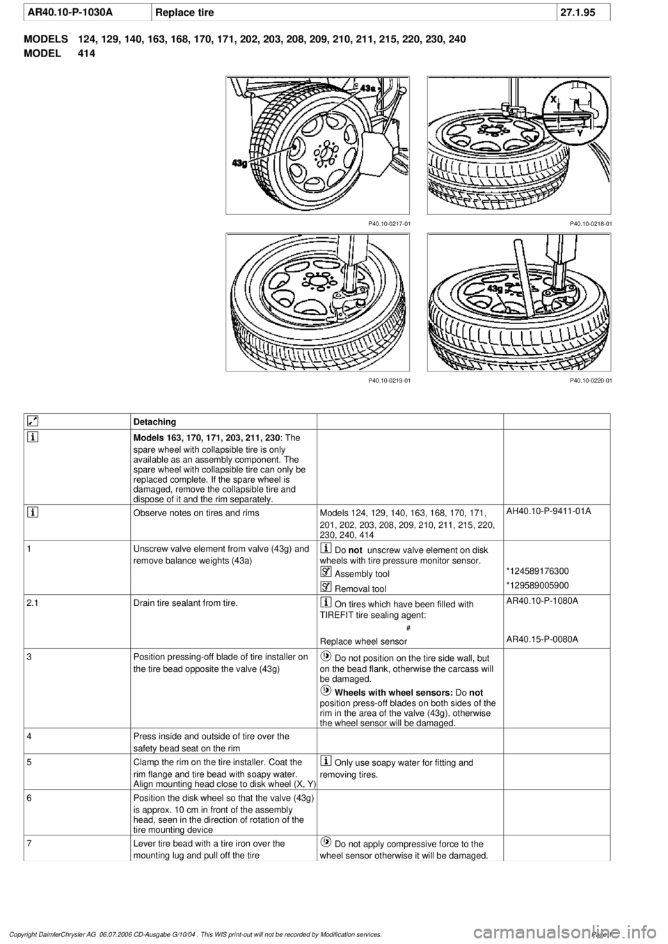
P40.10-0218-01
P40.10-0217-01
P40.10-0219-01 P40.10-0220-01
Detaching
Models 163, 170, 171, 203, 211, 230
: The
spare wheel with collapsible tire is only
available as an assembly component. The
spare wheel with collapsible tire can only be
replaced complete. If the spare wheel is
damaged, remove the collapsible tire and
dispose of it and the rim separately.
Observe notes on tires and rims
Models 124, 129, 140, 163, 168, 170, 171,
201, 202, 203, 208, 209, 210, 211, 215, 220,
230, 240, 414
AH40.10-P-9411-01A
1
Unscrew valve element from valve (43g) and
remove balance weights (43a)
Do
not
unscrew valve element on disk
wheels with tire pressure monitor sensor.
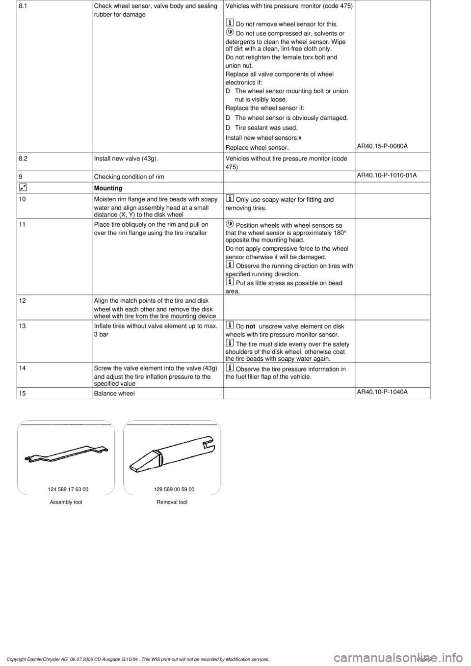
Assembly tool
*124589176300
Removal tool
*129589005900
2.1
Drain tire sealant from tire.
On tires which have been filled with
TIREFIT tire sealing agent:
#
AR40.10-P-1080A
Replace wheel sensor
AR40.15-P-0080A
3
Position pressing-off blade of tire installer on
the tire bead opposite the valve (43g)
Do not position on the tire side wall, but
on the bead flank, otherwise the carcass will
be damaged.
Wheels with wheel sensors:
Do
not
position press-off blades on both sides of the
rim in the area of the valve (43g), otherwise
the wheel sensor will be damaged.
4
Press inside and outside of tire over the
safety bead seat on the rim
5
Clamp the rim on the tire installer. Coat the
rim flange and tire bead with soapy water.
Align mounting head close to disk wheel (X, Y)
Only use soapy water for fitting and
removing tires.
6
Position the disk wheel so that the valve (43g)
is approx. 10 cm in front of the assembly
head, seen in the direction of rotation of the
tire mounting device
7
Lever tire bead with a tire iron over the
mounting lug and pull off the tire
Do not apply compressive force to the
wheel sensor otherwise it will be damaged.
Copyright DaimlerChrysler AG 06.07.2006 CD-Ausgabe G/10/04 . This WIS print-out will not be recorde
d by Modification services.
Page 1
Page 3778 of 4133
8.1
Check wheel sensor, valve body and sealing
rubber for damage
Vehicles with tire pressure monitor (code 475)
Do not remove wheel sensor for this.
Do not use compressed air, solvents or
detergents to clean the wheel sensor. Wipe
off dirt with a clean, lint-free cloth only.
Do not retighten the female torx bolt and
union nut.
Replace all valve components of wheel
electronics if:
D
The wheel sensor mounting bolt or union
nut is visibly loose.
Replace the wheel sensor if:
D
The wheel sensor is obviously damaged.
D
Tire sealant was used.
Install new wheel sensors:
#
Replace wheel sensor.
AR40.15-P-0080A
8.2
Install new valve (43g).
Vehicles without tire pressure monitor (code
475)
9
Checking condition of rim
AR40.10-P-1010-01A
Mounting
10
Moisten rim flange and tire beads with soapy
water and align assembly head at a small
distance (X, Y) to the disk wheel
Only use soapy water for fitting and
removing tires.
11
Place tire obliquely on the rim and pull on
over the rim flange using the tire installer
Position wheels with wheel sensors so
that the wheel sensor is approximately 180°
opposite the mounting head.
Do not apply compressive force to the wheel
sensor otherwise it will be damaged.
Observe the running direction on tires with
specified running direction.
Put as little stress as possible on bead
area.
12
Align the match points of the tire and disk
wheel with each other and remove the disk
wheel with tire from the tire mounting device
13
Inflate tires without valve element up to max.
3 bar
Do
not
unscrew valve element on disk
wheels with tire pressure monitor sensor.
The tire must slide evenly over the safety
shoulders of the disk wheel, otherwise coat
the tire beads with soapy water again.
14
Screw the valve element into the valve (43g)
and adjust the tire inflation pressure to the
specified value
Observe the tire pressure information in
the fuel filler flap of the vehicle.
15
Balance wheel
AR40.10-P-1040A
124 589 17 63 00 129 589 00 59 00
Removal tool
Assembly tool
Copyright DaimlerChrysler AG 06.07.2006 CD-Ausgabe G/10/04 . This WIS print-out will not be recorde
d by Modification services.
Page 2
Page 3989 of 4133
AR40.15-P-0080A
Remove/install wheel sensor
1.4.99
MODELS
210.074 /274 with CODE (475) Tire pressure indicator
MODELS
211 with CODE (475) Tire pressure indicator
MODELS
215 with CODE (475) Tire pressure indicator
MODELS
220 with CODE (475) Tire pressure indicator
MODELS
230 with CODE (475) Tire pressure indicator
MODELS
240 with CODE (475) Tire pressure indicator
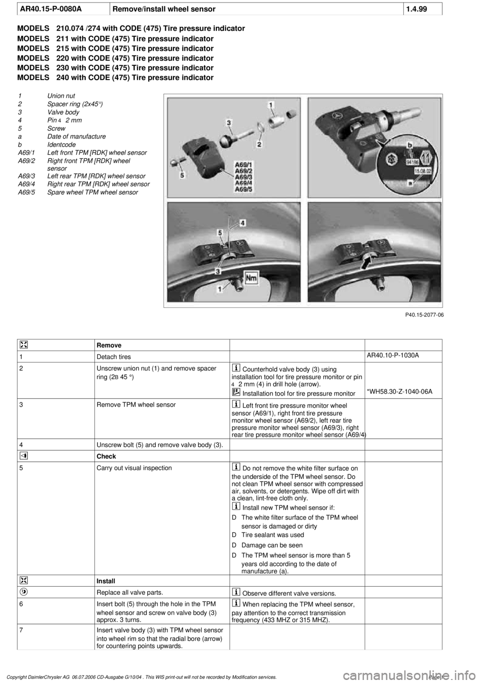
P40.15-2077-06
1
Union nut
2
Spacer ring (2x45°)
3
Valve body
4
Pin
4
2 mm
5
Screw
a
Date of manufacture
b
Identcode
A69/1
Left front TPM [RDK] wheel sensor
A69/2
Right front TPM [RDK] wheel
sensor
A69/3
Left rear TPM [RDK] wheel sensor
A69/4
Right rear TPM [RDK] wheel sensor
A69/5
Spare wheel TPM wheel sensor
Remove
1
Detach tires
AR40.10-P-1030A
2
Unscrew union nut (1) and remove spacer
ring (2
B
45 °)
Counterhold valve body (3) using
installation tool for tire pressure monitor or pin
4
2 mm (4) in drill hole (arrow).
Installation tool for tire pressure monitor
*WH58.30-Z-1040-06A
3
Remove TPM wheel sensor
Left front tire pressure monitor wheel
sensor (A69/1), right front tire pressure
monitor wheel sensor (A69/2), left rear tire
pressure monitor wheel sensor (A69/3), right
rear tire pressure monitor wheel sensor (A69/4)
4
Unscrew bolt (5) and remove valve body (3).
Check
5
Carry out visual inspection
Do not remove the white filter surface on
the underside of the TPM wheel sensor. Do
not clean TPM wheel sensor with compressed
air, solvents, or detergents. Wipe off dirt with
a clean, lint-free cloth only.
Install new TPM wheel sensor if:
D
The white filter surface of the TPM wheel
sensor is damaged or dirty
D
Tire sealant was used
D
Damage can be seen
D
The TPM wheel sensor is more than 5
years old according to the date of
manufacture (a).
Install
Replace all valve parts.
Observe different valve versions.
6
Insert bolt (5) through the hole in the TPM
wheel sensor and screw on valve body (3)
approx. 3 turns.
When replacing the TPM wheel sensor,
pay attention to the correct transmission
frequency (433 MHZ or 315 MHZ).
7
Insert valve body (3) with TPM wheel sensor
into wheel rim so that the radial bore (arrow)
for countering points upwards.
Copyright DaimlerChrysler AG 06.07.2006 CD-Ausgabe G/10/04 . This WIS print-out will not be recorde
d by Modification services.
Page 1
Page 3990 of 4133

8
Install spacer ring (2) and screw on union nut
(1) as far as the stop.
Counterhold valve body (3) using
installation tool for tire pressure monitor or pin
4
2 mm (4) in drill hole (arrow).
Installation tool for tire pressure monitor
*WH58.30-Z-1040-06A
9
Tighten union nut (1).
Secure valve body (2) using installation
tool for tire pressure monitor or pin
4
2 mm
(4), to prevent it from turning
After tightening, pull installation tool for
tire pressure monitor or pin
4
2 mm (4) out of
valve body (3). Danger of damage to tire.
Union nut to valve body
*BA40.15-P-1001-01A
Installation tool for tire pressure monitor
*WH58.30-Z-1040-06A
10
Press RPM wheel sensor gently into drop
center of rim and tighten bolt (5).
Internal torx bolt, wheel sensor to valve
body
*BA40.15-P-1002-01A
11
Note ID code (b) of new TPM wheel sensor.
It is advisable to record the code in the
owner's manual or maintenance booklet.
Initialization
12
Teach in new TPM wheel sensor in TPM
control unit using STAR DIAGNOSIS.
Diagnosis system STAR DIAGNOSIS
*WE58.40-Z-1013-06A
13
Activate the tire pressure monitoring system
Model 211
AR54.30-P-1000-02RAT
Model 230
AR54.30-P-1000-02RAR
Model 240
AR54.30-P-1000-02RAH
n
Tire pressure monitor (TPM), activation
Model 210
GF40.15-P-0001-02A
Model 215, 220 up to 30.9.00
GF40.15-P-0001-02B
Model 215, 220 as of 01.10.00 up to 31.05.01
GF40.15-P-0001-02C
Models 215, 220 as of 01.06.01 up to 31.08.02
GF40.15-P-0001-02D
Model 215, 220 as of 01.09.02
GF40.15-P-0001-02E
Tire pressure monitoring
Number
Designation
Model
210, 211,
215, 220,
230, 240
BA40.15-P-1001-01A
Union nut to valve body
Nm
4
BA40.15-P-1002-01A
Bolt, wheel sensor to valve body
Nm
4
Commercially available tools
(see Workshop Equipment Manual)
Number
Designation
Make (e. g.)
Order number
WH58.30-Z-1040-06A
Installation tool for tire pressure control
Alligator Ventilfabrik
GmbH
Postfach 1120
D-89526 Giengen
232540
Workshop equipment/MB testers
(see Workshop Equipment Manual)
WE58.40-Z-1013-06A
STAR DIAGNOSIS Compact diagnosis system for passenger cars, order number 6511 1801 00
Copyright DaimlerChrysler AG 06.07.2006 CD-Ausgabe G/10/04 . This WIS print-out will not be recorde
d by Modification services.
Page 2
Page 3993 of 4133
AR40.10-P-1010-01A
Checking condition of rim
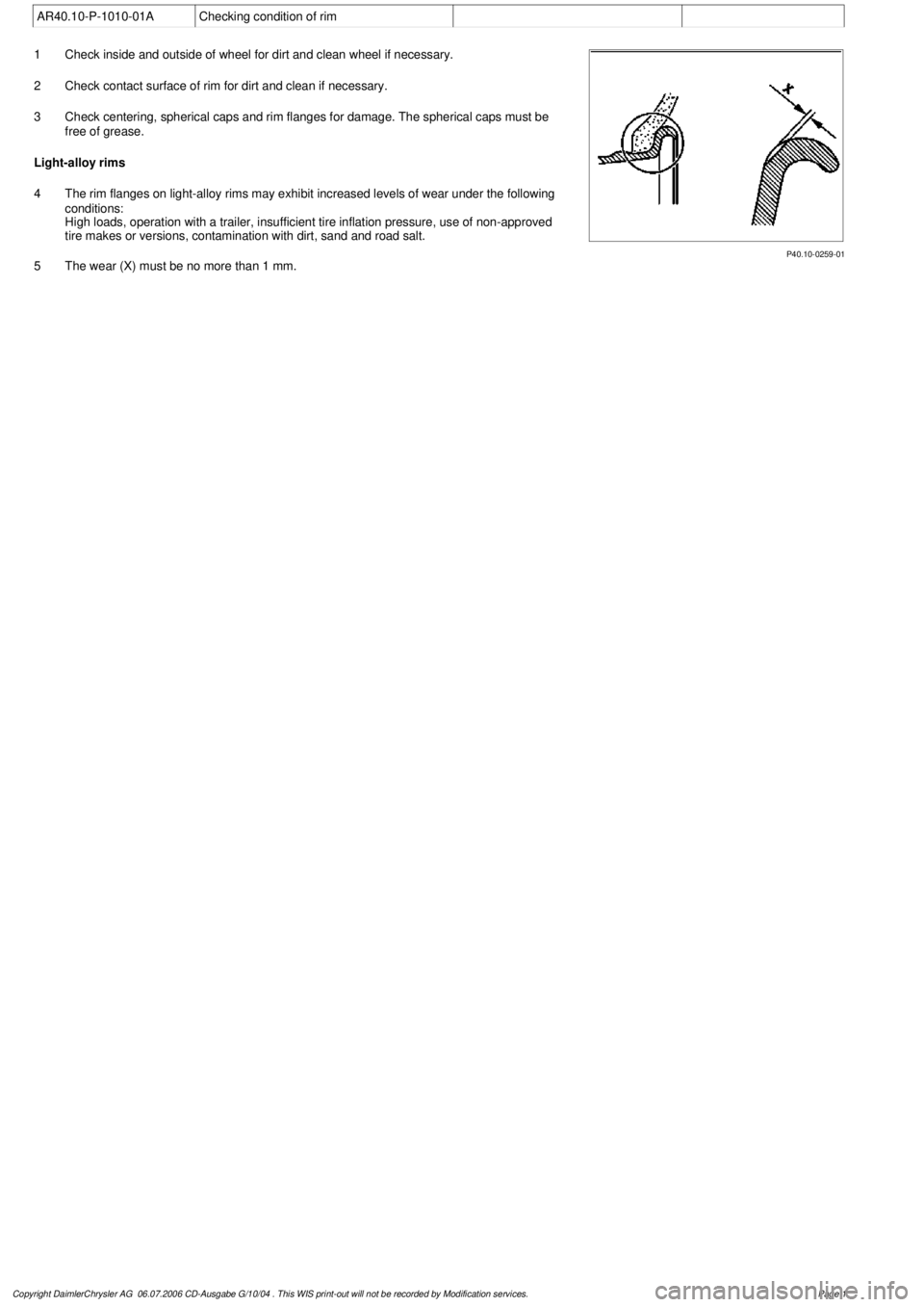
P40.10-0259-01
1
Check inside and outside of wheel for dirt and clean wheel if necessary.
2
Check contact surface of rim for dirt and clean if necessary.
3
Check centering, spherical caps and rim flanges for damage. The spherical caps must be
free of grease.
Light-alloy rims
4
The rim flanges on light-alloy rims may exhibit increased levels of wear under the following
conditions:
High loads, operation with a trailer, insufficient tire inflation pressure, use of non-approved
tire makes or versions, contamination with dirt, sand and road salt.
5
The wear (X) must be no more than 1 mm.
Copyright DaimlerChrysler AG 06.07.2006 CD-Ausgabe G/10/04 . This WIS print-out will not be recorde
d by Modification services.
Page 1
Page 3994 of 4133
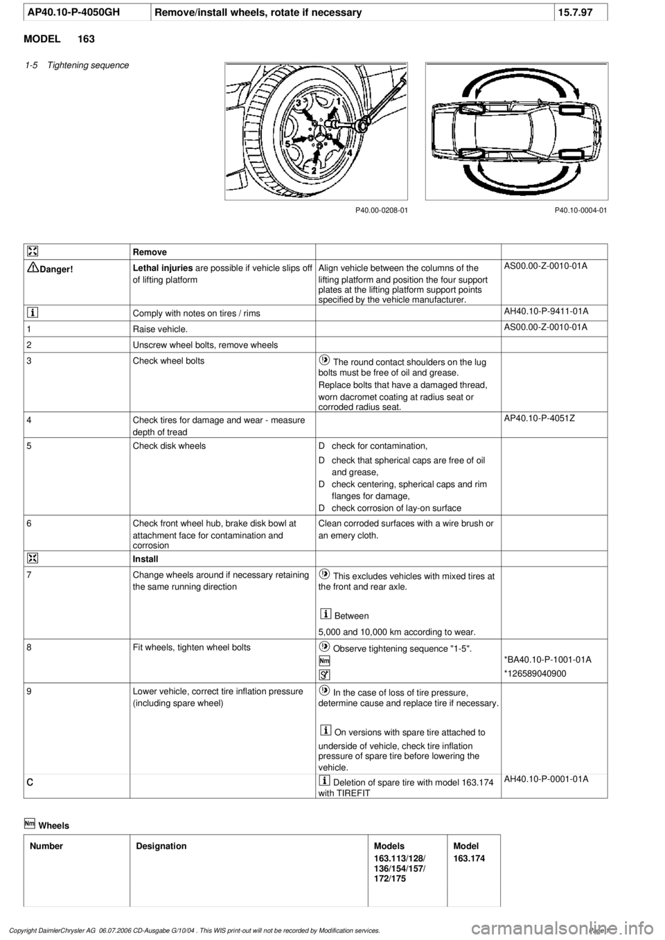
AP40.10-P-4050GH
Remove/install wheels, rotate if necessary
15.7.97
MODEL
163
1-5
Tightening sequence
P40.10-0004-01
P40.00-0208-01
Remove
Danger!
Lethal injuries
are possible if vehicle slips off
of lifting platform
Align vehicle between the columns of the
lifting platform and position the four support
plates
at the lifting platform support points
specified by the vehicle manufacturer.
AS00.00-Z-0010-01A
Comply with notes on tires / rims
AH40.10-P-9411-01A
1
Raise vehicle.
AS00.00-Z-0010-01A
2
Unscrew wheel bolts, remove wheels
3
Check wheel bolts
The round contact shoulders on the lug
bolts must be free of oil and grease.
Replace bolts that have a damaged thread,
worn dacromet coating at radius seat or
corroded radius seat.
4
Check tires for damage and wear - measure
depth of tread
AP40.10-P-4051Z
5
Check disk wheels
D
check for contamination,
D
check that spherical caps are free of oil
and grease,
D
check centering, spherical caps and rim
flanges for damage,
D
check corrosion of lay-on surface
6
Check front wheel hub, brake disk bowl at
attachment face for contamination and
corrosion
Clean corroded surfaces with a wire brush or
an emery cloth.
Install
7
Change wheels around if necessary retaining
the same running direction
This excludes vehicles with mixed tires at
the front and rear axle.
Between
5,000 and 10,000 km according to wear.
8
Fit wheels, tighten wheel bolts
Observe tightening sequence "1-5".
*BA40.10-P-1001-01A
*126589040900
9
Lower vehicle, correct tire inflation pressure
(including spare wheel)
In the case of loss of tire pressure,
determine cause and replace tire if necessary.
On versions with spare tire attached to
underside of vehicle, check tire inflation
pressure of spare tire before lowering the
vehicle.
c
Deletion of spare tire with model 163.174
with TIREFIT
AH40.10-P-0001-01A
Wheels
Number
Designation
Models
163.113/128/
136/154/157/
172/175
Model
163.174
Copyright DaimlerChrysler AG 06.07.2006 CD-Ausgabe G/10/04 . This WIS print-out will not be recorde
d by Modification services.
Page 1