1997 MERCEDES-BENZ ML320 tire pressure
[x] Cancel search: tire pressurePage 2136 of 4133
AR40.10-P-1080A
Draining TIREFIT sealant out of tires
18.6.96
MODEL
163.174
MODEL
168, 170, 171, 203, 209, 211, 230, 240
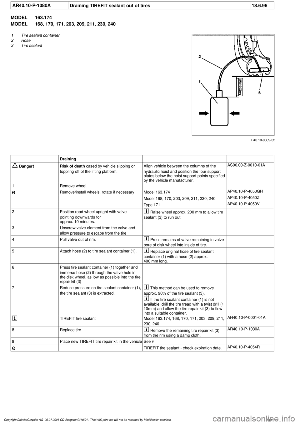
P40.10-0309-02
1
Tire sealant container
2
Hose
3
Tire sealant
Draining
Danger!
Risk of death
cased by vehicle slipping or
toppling off of the lifting platform.
Align vehicle between the columns of the
hydraulic hoist and position the four support
plates below the hoist support points specified
by the vehicle manufacturer.
AS00.00-Z-0010-01A
1
Remove wheel.
e
Remove/install wheels, rotate if necessary
Model 163.174
AP40.10-P-4050GH
Model 168, 170, 203, 209, 211, 230, 240
AP40.10-P-4050Z
Type 171
AP40.10-P-4050V
2
Position road wheel upright with valve
pointing downwards for
approx. 10 minutes.
Raise wheel approx. 200 mm to allow tire
sealant (3) to run out.
3
Unscrew valve element from the valve and
allow pressure to escape from the tire
4
Pull valve out of rim.
Press remains of valve remaining in valve
bore of disk wheel into inside of tire.
5
Attach hose (2) to tire sealant container (1).
Replace original hose of tire sealant
container (1) with a hose (2) approx.
400 mm long.
6
Press tire sealant container (1) together and
immerse hose (2) through the valve hole in
the disk wheel, as low as possible into the tire
repair kit (3)
7
Reduce pressure on tire sealant container (1),
the tire sealant (3) is extracted.
This method can be used to remove
approx. 90% of the tire sealant (3).
If the tire sealant container (1) is not
available, drill the tire tread with a twist drill (
4
10mm) and allow the tire repair kit (3) to flow
into a suitable container.
TIREFIT tire sealant
Model 163.174, 168, 170, 171, 203, 209, 211,
230, 240
AH40.10-P-0001-01A
8
Replace tire
Remove the remaining tire repair kit (3)
from the rim using a damp cloth.
AR40.10-P-1030A
9
Place new TIREFIT tire repair kit in the vehicle
See
#
e
TIREFIT tire sealant - check expiration date.
AP40.10-P-4054R
Copyright DaimlerChrysler AG 06.07.2006 CD-Ausgabe G/10/04 . This WIS print-out will not be recorde
d by Modification services.
Page 1
Page 3050 of 4133
SAFETY PRECAUTIONS FOR NEW VEHICLES THAT ARE BEING PUT IN STORAGE - AP00.70-P-1000ZZ
MODELS all
and rear axle
Frame
New vehicles in the
context of this description
are vehicles for which no
inspection has been carried
out to date. For other
vehicles, the instructions
in the Specifications for
Service Products apply
In areas in which
extremely high corrosive
attacks can be expected
from experience, the
measures given here are
not always sufficient even
for new vehiclesExport countries
In these cases, proceed in
accordance with
Specifications for Service
products.
Treatment of battery if
vehicle taken out of
service AR54.10-P-0006EA
Treatment of tire inflation
pressure if vehicle taken
out of serviceFor vehicles which will be
stored for longer than 2
months, the tire inflation
pressure should be
increased to approx. 4 bar
to prevent flattening of the
contact surface.
Treatment of break system
if vehicle taken out of
serviceWarm up service brake so
that adhering moisture at
the brake disks and the
brake pads evaporates.
This prevents the brake
pad from becoming stuck
to the brake disks.
Release parking brake.
The vehicle must be
secured by engaging a
gear/park pawl or by using
wedges.
Treatment of fuel system
if vehicle taken out of To protect the fuel tank
from corrosion, we
2004 Mercedes-Benz ML350
1998-2005 GENINFO Overall vehicle - 163 Chassis
me
Saturday, October 02, 2010 3:47:52 PMPage 405 © 2006 Mitchell Repair Information Company, LLC.
Page 3186 of 4133
AP82.10-P-8260GH
Check and correct headlamp adjustment
2.7.97
MODEL
163
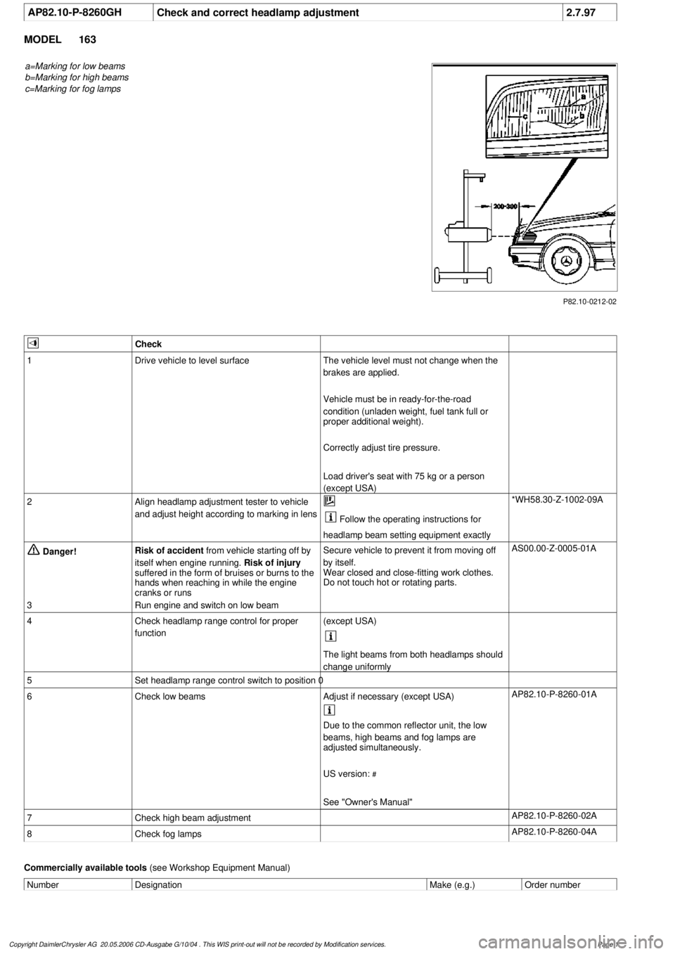
a=Marking for low beams
b=Marking for high beams
c=Marking for fog lamps
P82.10-0212-02
Check
1
Drive vehicle to level surface
The vehicle level must not change when the
brakes are applied.
Vehicle must be in ready-for-the-road
condition (unladen weight, fuel tank full or
proper additional weight).
Correctly adjust tire pressure.
Load driver's seat with 75 kg or a person
(except USA)
2
Align headlamp adjustment tester to vehicle
and adjust height according to marking in lens
Follow the operating instructions for
headlamp beam setting equipment exactly
*WH58.30-Z-1002-09A
Danger!
Risk of accident
from vehicle starting off by
itself when engine running.
Risk of injury
suffered in the form of bruises or burns to the
hands when reaching in while the engine
cranks or runs
Secure vehicle to prevent it from moving off
by itself.
Wear closed and close-fitting work clothes.
Do not touch hot or rotating parts.
AS00.00-Z-0005-01A
3
Run engine and switch on low beam
4
Check headlamp range control for proper
function
(except USA)
The light beams from both headlamps should
change uniformly
5
Set headlamp range control switch to position 0
6
Check low beams
Adjust if necessary (except USA)
AP82.10-P-8260-01A
Due to the common reflector unit, the low
beams, high beams and fog lamps are
adjusted simultaneously.
US version:
#
See "Owner's Manual"
7
Check high beam adjustment
AP82.10-P-8260-02A
8
Check fog lamps
AP82.10-P-8260-04A
Commercially available tools
(see Workshop Equipment Manual)
Number
Designation
Make (e.g.)
Order number
Copyright DaimlerChrysler AG 20.05.2006 CD-Ausgabe G/10/04 . This WIS print-out will not be recorde
d by Modification services.
Page 1
Page 3350 of 4133
value.
At the following values the electric fan for engine/AC (M4/7) is switched on or off:
refrigerant pressure > 20 bar = electric fan for engine/AC ON
refrigerant pressure <12 bar = electric fan for engine/AC OFF
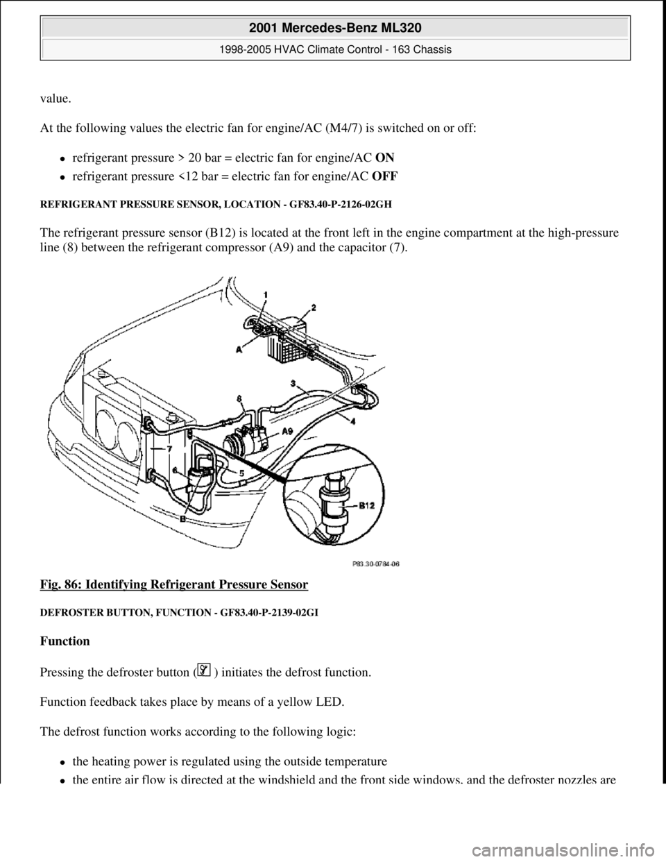
REFRIGERANT PRESSURE SENSOR, LOCATION - GF83.40-P-2126-02GH
The refrigerant pressure sensor (B12) is located at the front left in the engine compartment at the high-pressure
line (8) between the refrigerant compressor (A9) and the capacitor (7).
Fig. 86: Identifying Refrigerant Pressure Sensor
DEFROSTER BUTTON, FUNCTION - GF83.40-P-2139-02GI
Function
Pressing the defroster button ( ) initiates the defrost function.
Function feedback takes place by means of a yellow LED.
The defrost function works according to the following logic:
the heating power is regulated using the outside temperature
the entire air flow is directed at the windshield and the front side windows, and the defroster nozzles are
2001 Mercedes-Benz ML320
1998-2005 HVAC Climate Control - 163 Chassis
me
Saturday, October 02, 2010 3:23:16 PMPage 106 © 2006 Mitchell Repair Information Company, LLC.
Page 3398 of 4133
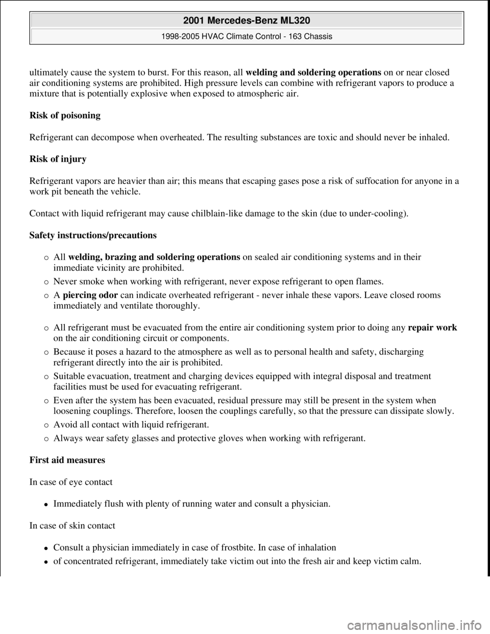
ultimately cause the system to burst. For this reason, all welding and soldering operations on or near closed
air conditioning systems are prohibited. High pressure levels can combine with refrigerant vapors to produce a
mixture that is potentially explosive when exposed to atmospheric air.
Risk of poisoning
Refrigerant can decompose when overheated. The resulting substances are toxic and should never be inhaled.
Risk of injury
Refrigerant vapors are heavier than air; this means that escaping gases pose a risk of suffocation for anyone in a
work pit beneath the vehicle.
Contact with liquid refrigerant may cause chilblain-like damage to the skin (due to under-cooling).
Safety instructions/precautions
All welding, brazing and soldering operations on sealed air conditioning systems and in their
immediate vicinity are prohibited.
Never smoke when working with refrigerant, never expose refrigerant to open flames.
A piercing odor can indicate overheated refrigerant - never inhale these vapors. Leave closed rooms
immediately and ventilate thoroughly.
All refrigerant must be evacuated from the entire air conditioning system prior to doing any repair work
on the air conditioning circuit or components.
Because it poses a hazard to the atmosphere as well as to personal health and safety, discharging
refrigerant directly into the air is prohibited.
Suitable evacuation, treatment and charging devices equipped with integral disposal and treatment
facilities must be used for evacuating refrigerant.
Even after the system has been evacuated, residual pressure may still be present in the system when
loosening couplings. Therefore, loosen the couplings carefully, so that the pressure can dissipate slowly.
Avoid all contact with liquid refrigerant.
Always wear safety glasses and protective gloves when working with refrigerant.
First aid measures
In case of eye contact
Immediately flush with plenty of running water and consult a physician.
In case of skin contact
Consult a physician immediately in case of frostbite. In case of inhalation
of concentrated refrigerant, immediately take victim out into the fresh air and keep victim calm.
2001 Mercedes-Benz ML320
1998-2005 HVAC Climate Control - 163 Chassis
me
Saturday, October 02, 2010 3:23:17 PMPage 154 © 2006 Mitchell Repair Information Company, LLC.
Page 3431 of 4133
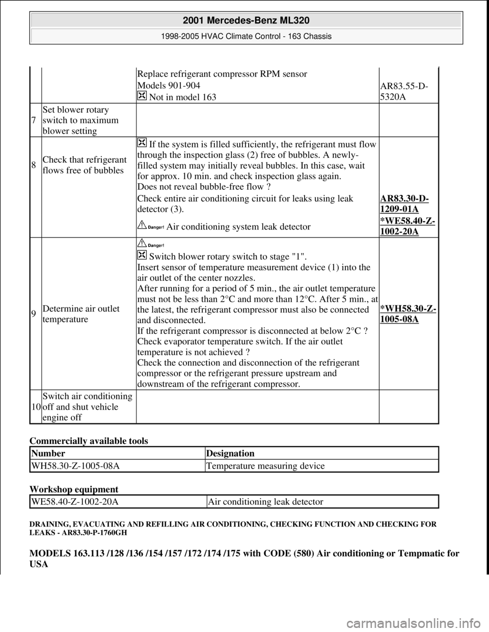
Commercially available tools
Workshop equipment
DRAINING, EVACUATING AND REFILLING AIR CONDITIONING, CHECKING FUNCTION AND CHECKING FOR
LEAKS - AR83.30-P-1760GH
MODELS 163.113 /128 /136 /154 /157 /172 /174 /175 with CODE (580) Air conditioning or Tempmatic for
USA
Replace refrigerant compressor RPM sensor
Models 901-904
Not in model 163AR83.55-D-
5320A
7
Set blower rotary
switch to maximum
blower setting
8Check that refrigerant
flows free of bubbles
If the system is filled sufficiently, the refrigerant must flow
through the inspection glass (2) free of bubbles. A newly-
filled system may initially reveal bubbles. In this case, wait
for approx. 10 min. and check inspection glass again.
Does not reveal bubble-free flow ?
Check entire air conditioning circuit for leaks using leak
detector (3).AR83.30-D-
1209-01A
Air conditioning system leak detector*WE58.40-Z-
1002-20A
9Determine air outlet
temperature
Switch blower rotary switch to stage "1".
Insert sensor of temperature measurement device (1) into the
air outlet of the center nozzles.
After running for a period of 5 min., the air outlet temperature
must not be less than 2°C and more than 12°C. After 5 min., at
the latest, the refrigerant compressor must also be connected
and disconnected.
If the refrigerant compressor is disconnected at below 2°C ?
Check evaporator temperature switch. If the air outlet
temperature is not achieved ?
Check the connection and disconnection of the refrigerant
compressor or the refrigerant pressure upstream and
downstream of the refrigerant compressor.
*WH58.30-Z-
1005-08A
10
Switch air conditioning
off and shut vehicle
engine off
NumberDesignation
WH58.30-Z-1005-08ATemperature measuring device
WE58.40-Z-1002-20AAir conditioning leak detector
2001 Mercedes-Benz ML320
1998-2005 HVAC Climate Control - 163 Chassis
me
Saturday, October 02, 2010 3:23:18 PMPage 187 © 2006 Mitchell Repair Information Company, LLC.
Page 3484 of 4133

AH40.10-P-9411-01A
Information on tires/rims
Model 124, 129, 140, 163, 168, 169,
170, 171, 199, 201, 202, 203, 208, 209,
210, 211, 215, 219, 220, 230, 240, 414,
450, 452,
639
Tires
D
For service conversions, the tire/disc wheel specifications and
dimensions should be compared with the entries in the
registration papers.
D
When mounting tires, the tires and rims must be carefully
matched in order to guarantee the concentricity of the wheel.
Identification of matching points on:
- Tires with a colored dot on the outside of the tire,
- Sheet steel disk wheel by a colored dot or punch mark on the
outside of the wheel,
- Perform this operation at the valve stem hole on light-alloy
disk wheels
With an additional paint spot or punch mark in the rim base
for the 140 Model Series.
D
Always replace the rubber valve.
-----------------------------------------------------------------------------------------
D
Damaged and defective tires must always be replaced. The
repair methods employed in the tire trade are not approved by
Mercedes-Benz. Small nicks (<0.8mm) on the tire's sidewall do
not usually pose a cause for concern, and continued use of
such tires is approved
D When replacing just one tire, install it on the front of the vehicle.
This does not apply to vehicles with different tires of varying
specifications on the front and rear wheels.
D
Only use tires listed in the valid Service Information bulletins
and repair instructions.
D
If the permissible maximum speed of an M+S tire is below the
maximum speed of the vehicle, an appropriate adhesive plate
must be attached in the driver's field of view.
-----------------------------------------------------------------------------------------
D
Tires permissible for higher speeds may be used.
D
Always fit all rims with tires of the same design, make and
version.
-----------------------------------------------------------------------------------------
D
Run in new tires for approx. 100 km at moderate speed.
D
Handed tires must be installed according to the arrow on the
side wall of the tire.
D
Tires are subject to an aging process with negative effects on
the properties of the tire. In order to ensure optimum
effectiveness in winter, M+S tires should not be used for longer
than 3 years.
-----------------------------------------------------------------------------------------
Tire pressure
(For specified values see tire pressure table in the fuel filler flap, on
the Vaneo BM 414 see B-pillar on the passenger side).
Too low tire pressure increases the rolling resistance and increases
the flexing energy of the tire. This causes the critical temperature limit
to be exceeded (carcass detachment) and destroys the tire. Respond
to loss of tire pressure by determining the source and replacing the
tire as indicated.
Cleaning
Using a spray wand with high-pressure nozzles to clean the wheel
can lead to tire damage. Such damage occurs especially on the tire
side walls. The following should be observed when using flat jet
nozzles:
D
Maintain a minimum distance of 300 mm
D
Do not direct the water jet at a single point on the surface of the
tire for any length of time.
-----------------------------------------------------------------------------------------
Mounting in bearings
Before putting into storage, clean tires thoroughly and check for
damage and adequate tread depth. Mark the position and running
direction of the tires with chalk. Do not store tires outdoors. Under the
influence of sunlight, heat, moving air and ozone the rubber looses
elasticity and strength, ages more quickly and becomes cracked.
Storage areas should be dry, cool and dark. Avoid drafts by keeping
doors and windows closed as much as possible. Do not bring tires
into contact with gasoline, oil or other greases as they dissolve the
rubber.
Disposal
Collection, storage and disposal should be performed in accordance
with the legal requirements and the company's own regulations.
-----------------------------------------------------------------------------------------
Copyright DaimlerChrysler AG 06.07.2006 CD-Ausgabe G/10/04 . This WIS print-out will not be recorde
d by Modification services.
Page 1
Page 3485 of 4133

Rims
D
When changing wheels, for instance, when replacing steel
wheels with light-alloy rims, ensure that the wheel bolts
required for the spare wheel are stored in a clearly visible
location.
D
Since December 1994 models 202 and 124 with special
equipment light alloy disk wheels, are supplied with a sheet
steel spare wheel instead of a light alloy spare wheel. The
necessary wheel bolts are included with the steel spare wheel.
D
Only use approved Mercedes-Benz rims of the same version.
D
Reinforced steel rims are identified by a sticker on the wheel
disc.
D
The wheel bolts on steel and light-alloy rims should always be
tightened to the specified tightening torque using a torque
wrench.
It is not necessary to retorque the lug bolts after approximately
100 to 500 km.
D
The seat for the tire bead must display no corrosion marks.
D
Before inserting a new rubber valve, clean the contact surfaces
on the disk wheel.
On sheet steel-disk wheel wheel trims must be fitted to support
the rubber valve.
Damaged or deformed rims must not be repaired.
Tire pressure monitor
D
Before replacing a tire, check the date of manufacturer of the
wheel sensor: wheel sensors which are more than 5 years old
must be replaced.
D
Use STAR DIAGNOSIS to read out the actual values of the tire
pressure monitor. Check the remaining life of the wheel sensor
battery, replace the wheel sensor if necessary.
Copyright DaimlerChrysler AG 06.07.2006 CD-Ausgabe G/10/04 . This WIS print-out will not be recorde
d by Modification services.
Page 2