Page 1599 of 4133
Map data.
The digitized map area on the CD-ROM contains towns, cities, streets, intersections and their attributes (e.g.:
one-way streets, turn prohibitions, ...). It does not contain information about company and private ground,
farms, housing estates and agricultural roads.
Gyrosensor
The gyrosensor determines the direction change of the vehicle. It is installed in the navigation processor .
Calibration is not required.
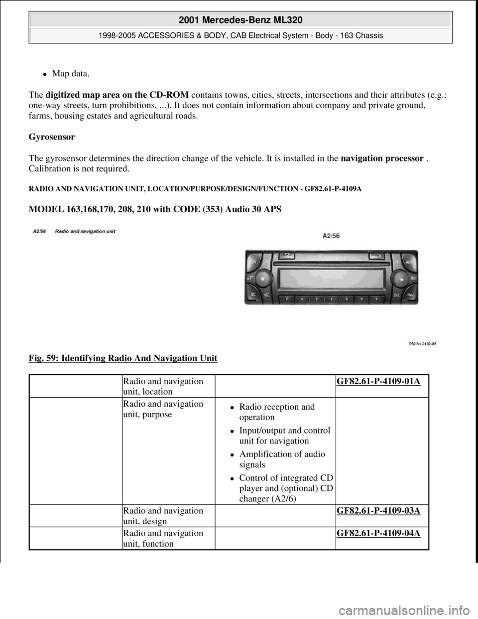
RADIO AND NAVIGATION UNIT, LOCATION/PURPOSE/DESIGN/FUNCTION - GF82.61-P-4109A
MODEL 163,168,170, 208, 210 with CODE (353) Audio 30 APS
Fig. 59: Identifying Radio And Navigation Unit
Radio and navigation
unit, location GF82.61-P-4109-01A
Radio and navigation
unit, purposeRadio reception and
operation
Input/output and control
unit for navigation
Amplification of audio
signals
Control of integrated CD
player and (optional) CD
changer (A2/6)
Radio and navigation
unit, design GF82.61-P-4109-03A
Radio and navigation
unit, function GF82.61-P-4109-04A
2001 Mercedes-Benz ML320
1998-2005 ACCESSORIES & BODY, CAB Electrical System - Body - 163 Chassis
me
Saturday, October 02, 2010 3:30:05 PMPage 104 © 2006 Mitchell Repair Information Company, LLC.
Page 1601 of 4133
SURVEY OF SYSTEM COMPONENTS, AUDIO 30 APS, LOCATION/TASK/ DESIGN/FUNCTION - GF82.61-P-9998ZZ
MODELS 163, 168, 170, 203.0 /2 /7, 208, 209.3 /4, 210 with CODE (353) Audio 30 APS
CD changer
(optional)
Sound system
(optional)
Navigation system
(optional)
Telephone (optional)
Radio and navigation
module, design GF82.61-P-4109-03GI
Radio and navigation
module, function GF82.61-P-4109-04GI
Radio and navigation unit,
location/task/design/ functionModel 163, 168,
170,208,210GF82.61-P-4109A
Model 209GF82.61-P-4109QA
Radio location/task/design/functionModel 203GF82.60-P-4109P
Additional fan for radio/navigation
unit, location/ taskModel 203 as of
1.6.03GF82.61-P-4110P
FM/AM antenna amplifier,
location/task/design/ functionModels 163, 168,
170, 208.4, 210.2GF82.62-P-4101A
Models 208.3, 210
(except, 210.2) with
code 352a
Antenna amplifier module,
location/task/design/ functionModels 203.0/7,
209.3GF82.62-P-3105PP
Model 203.2GF82.62-P-3105PS
Model 209.4GF82.62-P-3105QA
Rear window antenna,
location/task/design/ functionModels 203.0/7,
209.3GF82.62-P-3106PP
Model 203.2GF82.62-P-3106PS
Windshield antenna,
location/task/design/ functionModel 209.4GF82.62-P-3112Q
Radio reception antenna, location/taskModel 209.4GF82.62-P-4103Q
Radio reception amplifier, location/taskModel 209.4GF82.62-P-4104Q
Telephone antenna, location/taskModels 203.0/2/7,
209.3GF82.62-P-4105PP
Model 209.4GF82.62-P-4105Q
GPS/telephone roof antenna,
location/task/ design/functionModels 163, 168,
208.3, 210GF82.70-P-4111A
2001 Mercedes-Benz ML320
1998-2005 ACCESSORIES & BODY, CAB Electrical System - Body - 163 Chassis
me
Saturday, October 02, 2010 3:30:05 PMPage 106 © 2006 Mitchell Repair Information Company, LLC.
Page 1602 of 4133
Global positioning system antenna,
location / task / design / functionModels 170, 208.4GF82.61-P-4106A
Models 203.0/2/7,
209.3GF82.61-P-4106E
Global positioning system antenna,
location/ taskModel 209.4GF82.61-P-4107Q
Antenna splitter,
location/task/design/functionModel 163GF82.85-P-3107B
CD player with changer,
location/task/design/ functionModels 209.3/4GF82.64-P-3113Q
Models 203.0/2/7
with code (819) CD
changer 6-discGF82.64-P-3113PA
Models 163, 208,
210 with code (819)
CD changer 6-discGF82.64-P-3113B
Sound amplifier,
location/task/design/functionModels 209.3/4 with
code (810) sound
system
Models 203.0/2/7 up
to 23.4.04 with code
(810) Sound systemGF82.62-P-3100Q
Models 203.0/2/7 as
from 24.4.04 with
code (810) sound
system, except code
(498) Japan version,
except code (494a)
USA versionGF82.62-P-3100PM
Telephone interface,
location/task/design/ functionModels 203.0/2/7,
209.3/4GF82.70-P-3107Q
Transmitter/receiver unit,
location/task/design/ functionModels 203.0/2, 210
With code (853) MB
Standard telephone
With code (855)
TELE AID
With code (930)
Taxi emergency call
Models 203.7, 208.3,
209.3/4
With code (853) MB
Standard telephone
With code (855)
TELE AIDGF82.95-P-4300A
Table of contents, function description
of Audio 30 APS GF82.61-P-0998ZZ
2001 Mercedes-Benz ML320
1998-2005 ACCESSORIES & BODY, CAB Electrical System - Body - 163 Chassis
me
Saturday, October 02, 2010 3:30:05 PMPage 107 © 2006 Mitchell Repair Information Company, LLC.
Page 1605 of 4133
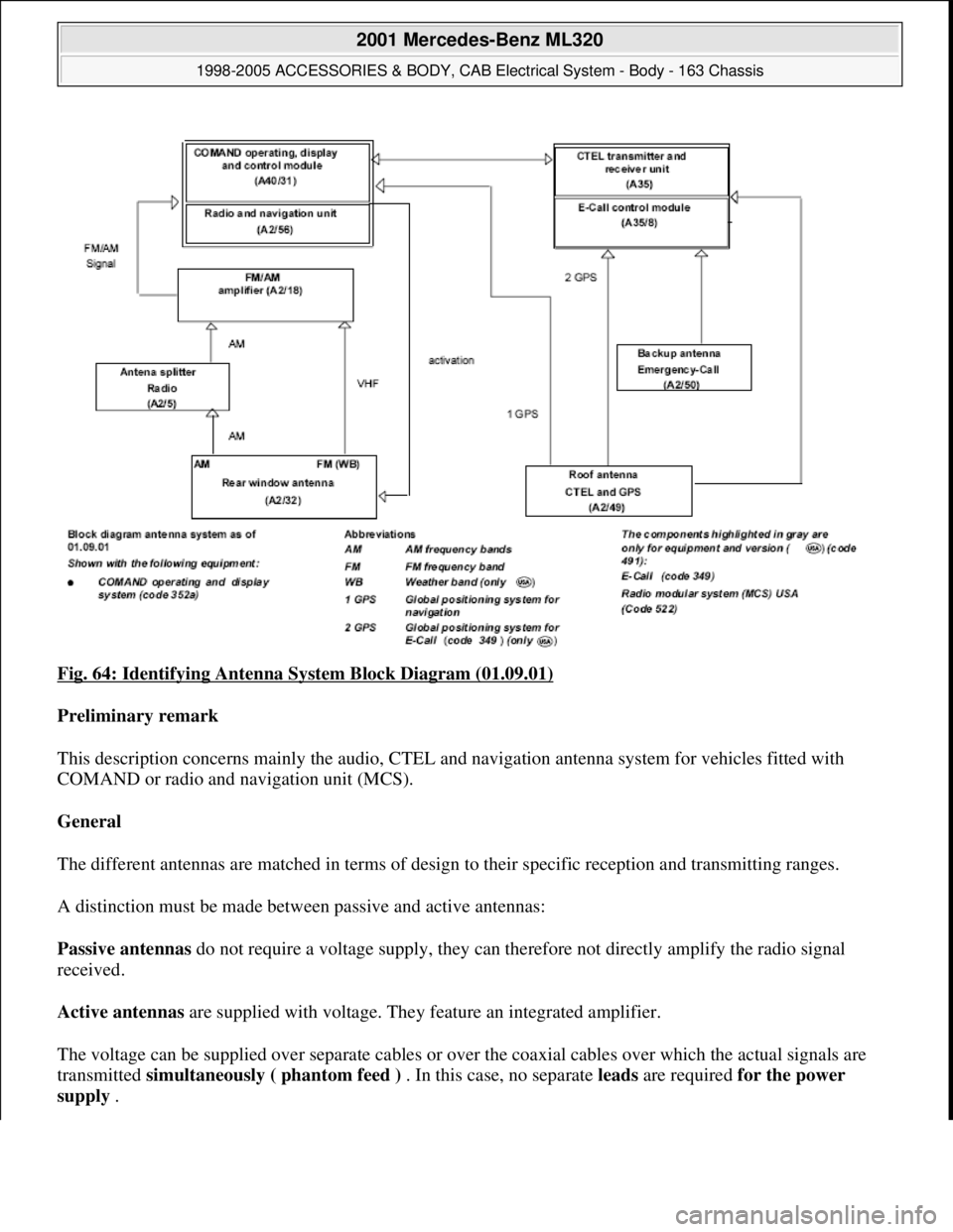
Fig. 64: Identifying Antenna System Block Diagram (01.09.01)
Preliminary remark
This description concerns mainly the audio, CTEL and navigation antenna system for vehicles fitted with
COMAND or radio and navigation unit (MCS).
General
The different antennas are matched in terms of design to their specific reception and transmitting ranges.
A distinction must be made between passive and active antennas:
Passive antennas do not require a voltage supply, they can therefore not directly amplify the radio signal
received.
Active antennas are supplied with voltage. They feature an integrated amplifier.
The voltage can be supplied over separate cables or over the coaxial cables over which the actual signals are
transmitted simultaneously ( phantom feed ) . In this case, no separate leads are required for the power
supply .
2001 Mercedes-Benz ML320
1998-2005 ACCESSORIES & BODY, CAB Electrical System - Body - 163 Chassis
me
Saturday, October 02, 2010 3:30:05 PMPage 110 © 2006 Mitchell Repair Information Company, LLC.
Page 1608 of 4133
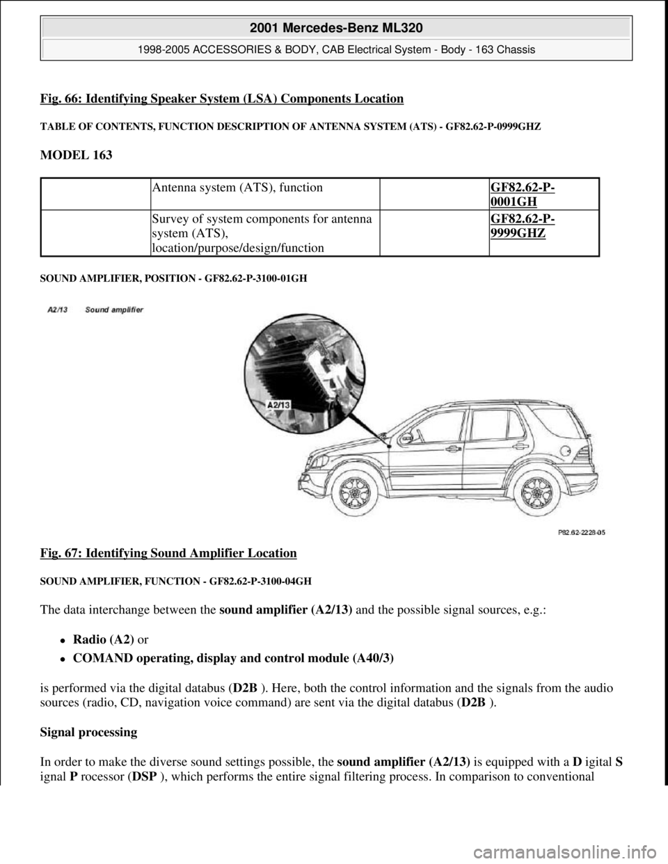
Fig. 66: Identifying Speaker System (LSA) Components Location
TABLE OF CONTENTS, FUNCTION DESCRIPTION OF ANTENNA SYSTEM (ATS) - GF82.62-P-0999GHZ
MODEL 163
SOUND AMPLIFIER, POSITION - GF82.62-P-3100-01GH
Fig. 67: Identifying Sound Amplifier Location
SOUND AMPLIFIER, FUNCTION - GF82.62-P-3100-04GH
The data interchange between the sound amplifier (A2/13) and the possible signal sources, e.g.:
Radio (A2) or
COMAND operating, display and control module (A40/3)
is performed via the digital databus (D2B ). Here, both the control information and the signals from the audio
sources (radio, CD, navigation voice command) are sent via the digital databus (D2B ).
Signal processing
In order to make the diverse sound settings possible, the sound amplifier (A2/13) is equipped with a D igital S
ignal P rocessor (DSP ), which performs the entire signal filtering process. In comparison to conventional
Antenna system (ATS), function GF82.62-P-
0001GH
Survey of system components for antenna
system (ATS),
location/purpose/design/function GF82.62-P-
9999GHZ
2001 Mercedes-Benz ML320
1998-2005 ACCESSORIES & BODY, CAB Electrical System - Body - 163 Chassis
me
Saturday, October 02, 2010 3:30:06 PMPage 113 © 2006 Mitchell Repair Information Company, LLC.
Page 1609 of 4133
analog filters, digital filters contain the following significant advantages:
the filter parameters (sound settings) do not alter throughout the period, this thus means that all the
settings can be repeated exactly
low noise level
the component outlay is significantly reduced, as the filter parameters are set by the software and not by
varying component values (resistances, capacitances or inductance values), thus the number of possible
filter settings is increased
Sound optimizations
Each of the six amplifier channels is equipped with an individual compensation, which can, when requested,
rectify the vehicle's acoustics. In addition further sound optimization settings can be made and effects such as,
e.g. 'voice emphasizing' or 'stereoscopic sound' invoked.
Bass, treble, volume, balance, fader and the dynamic loudness function can be individually set.
Noise suppression
The output level of the six 6 output stages is constantly monitored and regulated such that distortion is kept to a
minimum.
Automatic Vehicle Noise Compensation (VNC))
With the aid of the sound amplifier microphone (B25/6) , which is connected directly to the sound amplifier
(A2/13) , the noise level in the vehicle is measured. The volume of the music output signal is constantly adapted
to this noise level. To this end the sound amplifier (A2/13) must be able to detect which of the measured
signals are noise emissions from the moving vehicle and which are audio signals. This is conducted by
comparing the output signal of the sound amplifier (A2/13) with the measured signal.
Put simply, the vehicle noise level is the difference between the two signals.
Diagnosis
The sound amplifier (A2/13) can set up the following messages which are relevant for the diagnosis:
Operating status
Undervoltage
Internal fault in the sound amplifier (A2/13)
The messages are sent over the digital databus ( D2B ) to the COMAND operating, display and control
module (A40/3) or the radio (A2) , and can be read out there over the ( K-wire ) diagnostics line.
SOUND AMPLIFIER, LOCATION/TASK/DESIGN/FUNCTION - GF82.62-P-3100GH
MODEL 163 with CODE (810) sound system
2001 Mercedes-Benz ML320
1998-2005 ACCESSORIES & BODY, CAB Electrical System - Body - 163 Chassis
me
Saturday, October 02, 2010 3:30:06 PMPage 114 © 2006 Mitchell Repair Information Company, LLC.
Page 1610 of 4133
REAR WINDOW ANTENNAS, DESIGN - GF82.62-P-3106-03GH
Model 163
Antenna ranges
Sound amplifier,
position GF82.62-P-3100-
01GH
Sound amplifier, taskProcessing (sound settings)
and amplification of all audio
signals (radio, cassette, CD,
navigation voice command,..)
Sound amplifier, designDigital databus interface
(D2B)
Connection for sound
amplifier microphone
(B25/6) for automatic
vehicle noise
compensation
Digital filter technology
outputs distributed
across following
loudspeaker groups:
Treble
Medium treble
Medium bass
Bass
These are distributed as
follows:
Left front
Right front
Left rear
Rear right
Center
Woofer
Sound amplifier,
function GF82.62-P-3100-
04GH
2001 Mercedes-Benz ML320
1998-2005 ACCESSORIES & BODY, CAB Electrical System - Body - 163 Chassis
me
Saturday, October 02, 2010 3:30:06 PMPage 115 © 2006 Mitchell Repair Information Company, LLC.
Page 1613 of 4133
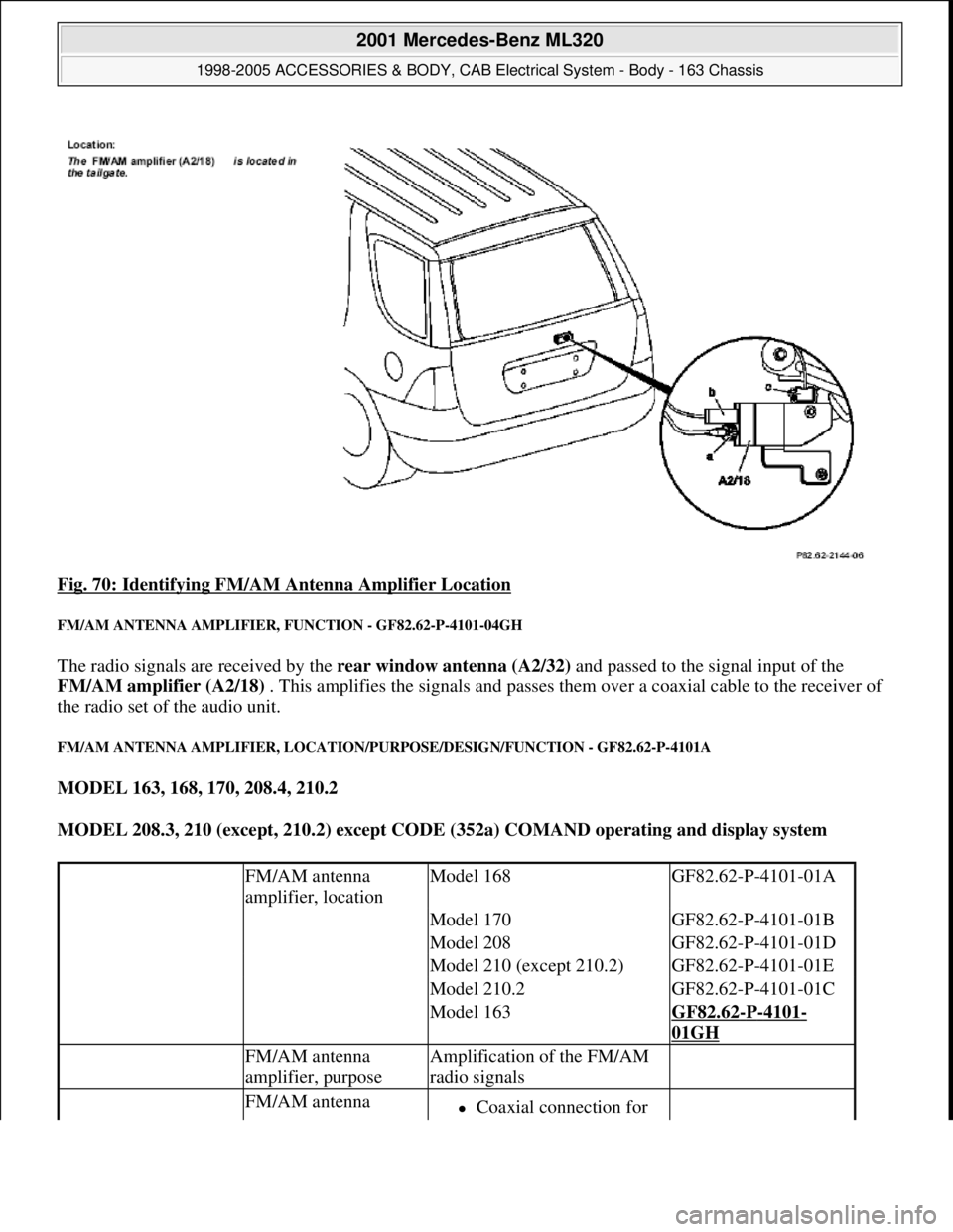
Fig. 70: Identifying FM/AM Antenna Amplifier Location
FM/AM ANTENNA AMPLIFIER, FUNCTION - GF82.62-P-4101-04GH
The radio signals are received by the rear window antenna (A2/32) and passed to the signal input of the
FM/AM amplifier (A2/18) . This amplifies the signals and passes them over a coaxial cable to the receiver of
the radio set of the audio unit.
FM/AM ANTENNA AMPLIFIER, LOCATION/PURPOSE/DESIGN/FUNCTION - GF82.62-P-4101A
MODEL 163, 168, 170, 208.4, 210.2
MODEL 208.3, 210 (except, 210.2) except CODE (352a) COMAND operating and display system
FM/AM antenna
amplifier, locationModel 168GF82.62-P-4101-01A
Model 170GF82.62-P-4101-01B
Model 208GF82.62-P-4101-01D
Model 210 (except 210.2)GF82.62-P-4101-01E
Model 210.2GF82.62-P-4101-01C
Model 163GF82.62-P-4101-
01GH
FM/AM antenna
amplifier, purposeAmplification of the FM/AM
radio signals
FM/AM antenna Coaxial connection for
2001 Mercedes-Benz ML320
1998-2005 ACCESSORIES & BODY, CAB Electrical System - Body - 163 Chassis
me
Saturday, October 02, 2010 3:30:06 PMPage 118 © 2006 Mitchell Repair Information Company, LLC.