1997 MERCEDES-BENZ ML320 length
[x] Cancel search: lengthPage 1611 of 4133
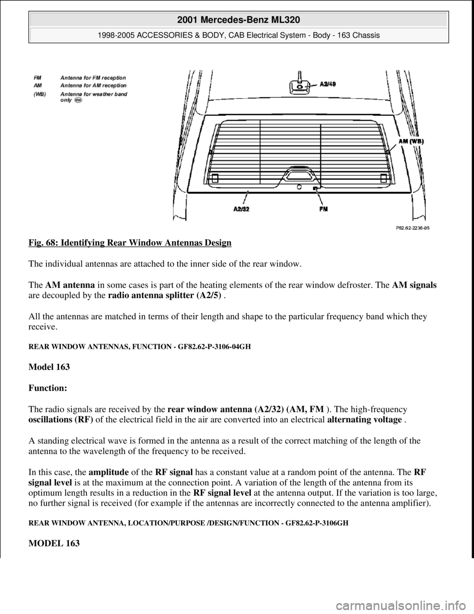
Fig. 68: Identifying Rear Window Antennas Design
The individual antennas are attached to the inner side of the rear window.
The AM antenna in some cases is part of the heating elements of the rear window defroster. The AM signals
are decoupled by the radio antenna splitter (A2/5) .
All the antennas are matched in terms of their length and shape to the particular frequency band which they
receive.
REAR WINDOW ANTENNAS, FUNCTION - GF82.62-P-3106-04GH
Model 163
Function:
The radio signals are received by the rear window antenna (A2/32) (AM, FM ). The high-frequency
oscillations (RF) of the electrical field in the air are converted into an electrical alternating voltage .
A standing electrical wave is formed in the antenna as a result of the correct matching of the length of the
antenna to the wavelength of the frequency to be received.
In this case, the amplitude of the RF signal has a constant value at a random point of the antenna. The RF
signal level is at the maximum at the connection point. A variation of the length of the antenna from its
optimum length results in a reduction in the RF signal level at the antenna output. If the variation is too large,
no further signal is received (for example if the antennas are incorrectly connected to the antenna amplifier).
REAR WINDOW ANTENNA, LOCATION/PURPOSE /DESIGN/FUNCTION - GF82.62-P-3106GH
MODEL 163
2001 Mercedes-Benz ML320
1998-2005 ACCESSORIES & BODY, CAB Electrical System - Body - 163 Chassis
me
Saturday, October 02, 2010 3:30:06 PMPage 116 © 2006 Mitchell Repair Information Company, LLC.
Page 1667 of 4133
CDS AND DVDS ARE NOT EJECTED - AF82.60-P-6061A
MODEL 129, 140, 163, 168, 170, 171, 202, 203, 208, 209, 210, 211, 215, 220, 230, 414, 463
Modification notes
5 Reinstall antenna
splitterAR82.70-P-8953GH
6 Reinstall AM/FM
amplifierAR82.62-P-8347GH
17.5.04Cause/remedy 3 added
Damage codeCauseRemedy
The causes listed in
this document are not a
malfunction of the CD
drive. Operations in
this context are not
covered b
y warranty or
goodwill .
Cause 1: Remedy 1:
CD thickness is not within
tolerance, e.g. DVDs with
recordings on both sides
(side 1: video data, side 2
audio data).1 Inform customer that
CDs should correspond
to specifications.
CD occasionally not
pulled in, light pressure
required in addition. Then,
CD is not ejected. Drives fulfill
specifications.
CD does not satisfy
specifications. According to
CD standards, the thickness
must be within the tolerance
range of 1.1 mm -1.5 mm.
Previously measured CDs
had a thickness of > or = 1.6
mm.
NoneCause 2: Remedy 2:
Self-made CDs/DVDs used
with self-adhesive labels.1 Advise customers not
to use CDs/DVDs with
self-adhesive labels.
Due to the various
materials used, the length
expansion differs at higher Please also advise
your coworkers in Sales.
2001 Mercedes-Benz ML320
1998-2005 ACCESSORIES & BODY, CAB Electrical System - Body - 163 Chassis
me
Saturday, October 02, 2010 3:30:07 PMPage 172 © 2006 Mitchell Repair Information Company, LLC.
Page 1825 of 4133
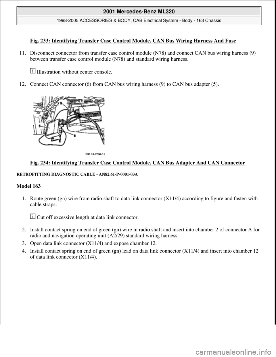
Fig. 233: Identifying Transfer Case Control Module, CAN Bus Wiring Harness And Fuse
11. Disconnect connector from transfer case control module (N78) and connect CAN bus wiring harness (9)
between transfer case control module (N78) and standard wiring harness.
Illustration without center console.
12. Connect CAN connector (6) from CAN bus wiring harness (9) to CAN bus adapter (5).
Fig. 234: Identifying Transfer Case Control Module, CAN Bus Adapter And CAN Connector
RETROFITTING DIAGNOSTIC CABLE - AN82.61-P-0001-03A
Model 163
1. Route green (gn) wire from radio shaft to data link connector (X11/4) according to figure and fasten with
cable straps.
Cut off excessive length at data link connector.
2. Install contact spring on end of green (gn) wire in radio shaft and insert into chamber 2 of connector A for
radio and navigation operating unit (A2/29) standard wiring harness.
3. Open data link connector (X11/4) and expose chamber 12.
4. Install contact spring on end of green (gn) lead on data link connector (X11/4) and insert into chamber 12
of data link connector (X11/4).
2001 Mercedes-Benz ML320
1998-2005 ACCESSORIES & BODY, CAB Electrical System - Body - 163 Chassis
me
Saturday, October 02, 2010 3:30:10 PMPage 330 © 2006 Mitchell Repair Information Company, LLC.
Page 1831 of 4133
(min. 60°), drive another
300 meters straight ahead
and then turn again, etc.
It makes no difference for
the calibration if the course
of the road does not allow
the vehicle to be driven the
specified route straight
ahead or to turn min. 60°.
This only increases the
length of the route to be
driven. Calibration is
completed when the location
is indicated in the AUDIO
mode (without active
objective guidance) when
the INFO button is pressed.
However, the location
can only be displayed when
the vehicle is driven on a
digitized road.
11Perform test driveCall up navigation menu by
pressing the NAV
multifunction button.
Enter destination (see
operating instructions) and
drive to destination.
Start-up stepAction on keypadFeedback on display
Accelerated start-up
1Insert navigation CDLoading time can take
several minutes
2Navigation menuCall navigation menu by
pressing NAV buttonLANGUAGE POS
TIME WHEEL
3Call default calibration
values Select the menu
"ADDRESS ENTRY" b
y
turning right knob (10)
and confirm by pressing
knob (10). Press
multifunction buttons 2
and 7 one after another
and then release
simultaneously. Press
multifunction button
KAL.
CAL
Select the menu Vehicle menu appears
2001 Mercedes-Benz ML320
1998-2005 ACCESSORIES & BODY, CAB Electrical System - Body - 163 Chassis
me
Saturday, October 02, 2010 3:30:11 PMPage 336 © 2006 Mitchell Repair Information Company, LLC.
Page 1921 of 4133
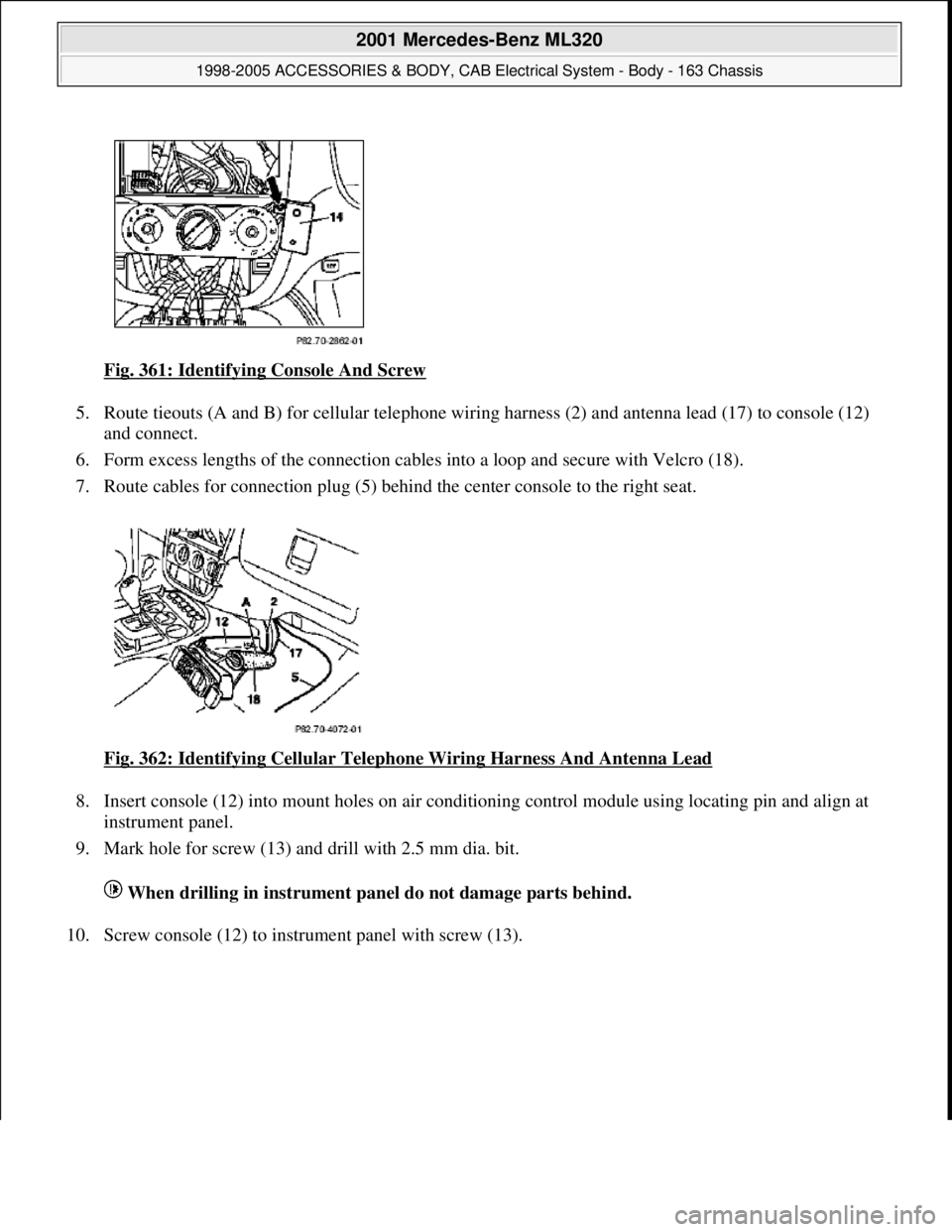
Fig. 361: Identifying Console And Screw
5. Route tieouts (A and B) for cellul ar telephone wiring harness (2) and an tenna lead (17) to console (12)
and connect.
6. Form excess lengths of the connection cables into a loop and secure with Velcro (18).
7. Route cables for connection plug (5) behi nd the center console to the right seat.
Fig. 362: Identifying Cellular Telepho ne Wiring Harness And Antenna Lead
8. Insert console (12) into mount holes on air condi tioning control module using locating pin and align at
instrument panel.
9. Mark hole for screw (13) and drill with 2.5 mm dia. bit.
When drilling in instrument pa nel do not damage parts behind.
10. Screw console (12) to instru ment panel with screw (13).
2001 Mercedes-Benz ML320
1998-2005 ACCESSORIES & BODY, CAB Electr ical System - Body - 163 Chassis
me
Saturday, October 02, 2010 3:30:13 PMPage 426 © 2006 Mitchell Repair Information Company, LLC.
Page 1926 of 4133
1. Shop-make wiring harness as specified in steps 2 to 6.
2. Cut cables at connection adapter (20) to length of approx. 150 mm.
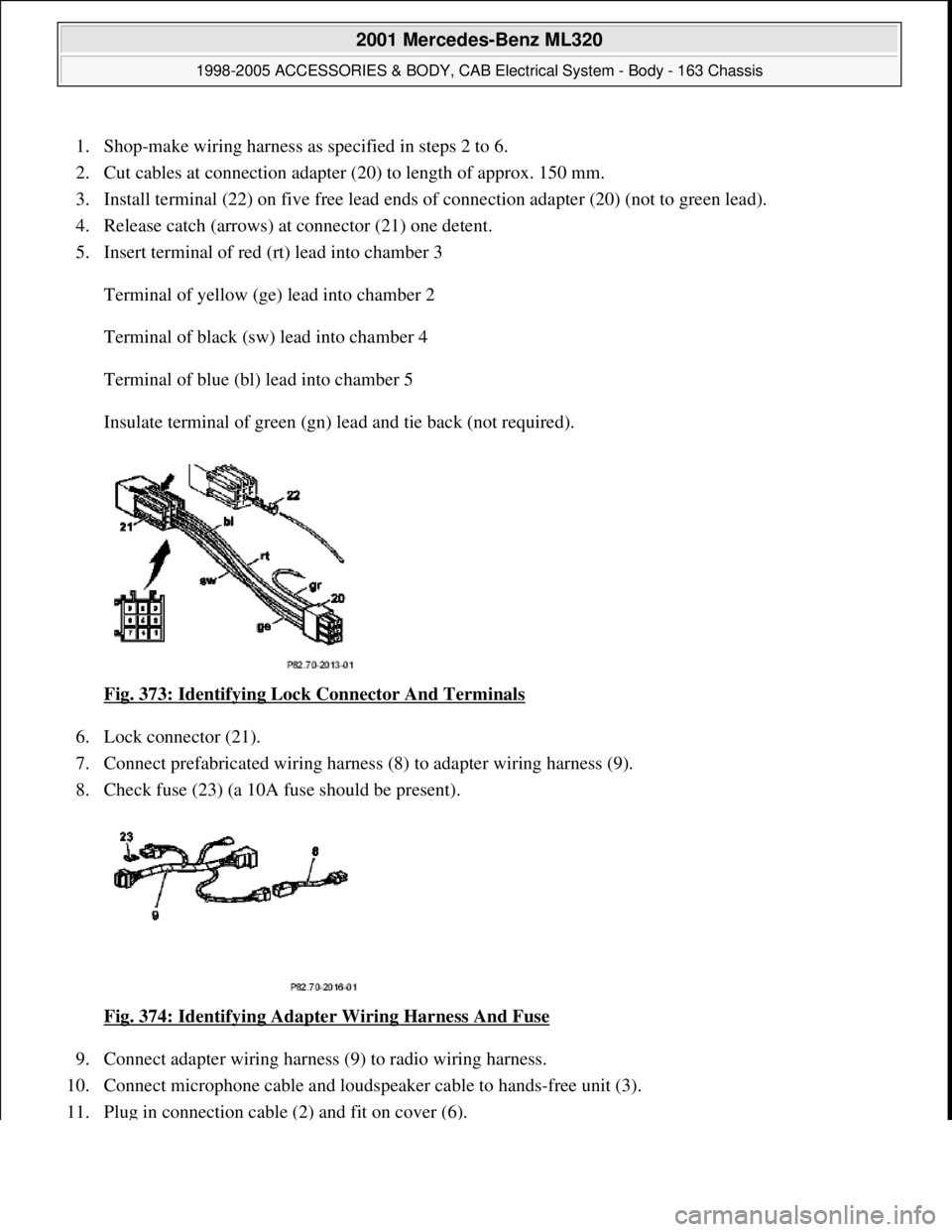
3. Install terminal (22) on five fr ee lead ends of connection adapter (20) (not to green lead).
4. Release catch (arrows) at connector (21) one detent.
5. Insert terminal of red (rt) lead into chamber 3
Terminal of yellow (ge) lead into chamber 2
Terminal of black (sw) lead into chamber 4
Terminal of blue (bl) lead into chamber 5
Insulate terminal of green (gn) lead and tie back (not required).
Fig. 373: Identifying Lock Connector And Terminals
6. Lock connector (21).
7. Connect prefabricated wiring harness (8) to adapter wiring harness (9).
8. Check fuse (23) (a 10A fuse should be present).
Fig. 374: Identifying Adapter Wiring Harness And Fuse
9. Connect adapter wiring harness (9) to radio wiring harness.
10. Connect microphone cable and loudspeaker cable to hands-free unit (3).
11. Plu
g in connection cable (2) and fit on cover (6).
2001 Mercedes-Benz ML320
1998-2005 ACCESSORIES & BODY, CAB Electr ical System - Body - 163 Chassis
me
Saturday, October 02, 2010 3:30:13 PMPage 431 © 2006 Mitchell Repair Information Company, LLC.
Page 2089 of 4133

29
Slacken cylinder head bolts (21) in stages,
unscrew
Loosen cylinder head bolts according to
loosening schematic only after engine has
cooled down to prevent cylinder head from
distorting.
AR01.30-P-5800-09B
Installation:
Observe tightening pattern
and tightening instructions of cylinder head
bolts.
Oil thread and head contact surface of
cylinder head bolts.
AR01.30-P-5800-07B
Screwdriver insert
*000589031000
Screwdriver insert
*000589041000
*BA01.30-P-1001-01D
30
Remove cylinder head
Installation:
On Engine 112/113 observe
porous points in the left and right cylinder
head. If porous points are present, sealant
must be applied to the cylinder head gasket.
Notes on application of sealant to cylinder
head gasket.
Engine 112, 113
AH01.30-P-1000-04VA
The sealant must be applied within
10 minutes.
Loctite 5900 sealant.
*BR00.45-Z-1015-01A
31
Inspect version of cylinder head gasket
Assignment of cylinder head gasket
Information for assigning the cylinder head
gaskets
Engine 112, 113
AH01.30-P-1000-06V
32
Check cylinder head bolts (21)
AR01.30-P-5800-03B
*BE01.30-P-1001-04B
33
Clean sealing surfaces, inspect for cracks,
shrink holes and flatness, clean threaded
holes.
Pay attention to dowel sleeves (26) for
locating the cylinder head.
Sealing surfaces of crankcase and
cylinder head are provided with an 0.8 mm
thick silicone layer during series production.
At the time of repair installation, silicone
sealant is applied to the sealing area only in
case of any shrink holes.
The sealant must be applied within
10 minutes.
Loctite 5900 sealant.
*BR00.45-Z-1015-01A
34
Install in the reverse order
Danger!
Risk of accident
caused by vehicle starting
off by itself when engine is running.
Risk of
injury
caused by contusions and burns when
working in engine during starting procedure
Secure vehicle to prevent it from moving.
Wear closed and snug-fitting work clothes.
Do not grasp hot or rotating parts.
AS00.00-Z-0005-01A
35
Run engine and inspect for leaks
36
Inspect cooling system for leaks
Warm up engine to operating temperature
and then inspect cooling system or leaks.
AR20.00-P-1010HA
37
Read out and erase fault memory
Stored faults which can result from cables
being disconnected or from simulation during
removal and installation or test work, have to
be processed and erased in the fault
memories after completing the work:
#
Diagnosis Manual Volume 2 Index 0:
Connecting and using test equipment.
Cylinder head/cylinder head bolts
Number
Designation
Engine
112.910/911/912/
913/914/915/
916/917/920/
921/922/923/
940/941/942/
943/944/945/
946/947/949/
951/953/954/
955/960/961/
970/972/973/975
Engine
113.940/941/
942/943/944/
945/946/948/
960/961/962/
963/965/966/
967/968/969/
980/981/982/
984/986/987/
988/990/991/
992/993
BE01.30-P-1001-04B
Cylinder head bolt
Thread diameter
M
1111
Length (L) when new
mm
141.5141.5
Length (L)
mm
T
144.5
T
144.5
Copyright DaimlerChrysler AG 20.05.2006 CD-Ausgabe G/10/04 . This WIS print-out will not be recorde
d by Modification services.
Page 5
Page 2097 of 4133

29
Slacken cylinder head bolts (21) in stages,
unscrew
Loosen cylinder head bolts according to
loosening schematic only after engine has
cooled down to prevent cylinder head from
distorting.
AR01.30-P-5800-09B
Installation:
Observe tightening pattern
and tightening instructions of cylinder head
bolts.
Oil thread and head contact surface of
cylinder head bolts.
AR01.30-P-5800-07B
Screwdriver insert
*000589031000
Screwdriver insert
*000589041000
*BA01.30-P-1001-01D
30
Remove cylinder head
Installation:
On Engine 112/113 observe
porous points in the left and right cylinder
head. If porous points are present, sealant
must be applied to the cylinder head gasket.
Notes on application of sealant to cylinder
head gasket.
Engine 112, 113
AH01.30-P-1000-04VA
The sealant must be applied within
10 minutes.
Loctite 5900 sealant.
*BR00.45-Z-1015-01A
31
Inspect version of cylinder head gasket
Assignment of cylinder head gasket
Information for assigning the cylinder head
gaskets
Engine 112, 113
AH01.30-P-1000-06V
32
Check cylinder head bolts (21)
AR01.30-P-5800-03B
*BE01.30-P-1001-04B
33
Clean sealing surfaces, inspect for cracks,
shrink holes and flatness, clean threaded
holes.
Pay attention to dowel sleeves (26) for
locating the cylinder head.
Sealing surfaces of crankcase and
cylinder head are provided with an 0.8 mm
thick silicone layer during series production.
At the time of repair installation, silicone
sealant is applied to the sealing area only in
case of any shrink holes.
The sealant must be applied within
10 minutes.
Loctite 5900 sealant.
*BR00.45-Z-1015-01A
34
Install in the reverse order
Danger!
Risk of accident
caused by vehicle starting
off by itself when engine is running.
Risk of
injury
caused by contusions and burns when
working in engine during starting procedure
Secure vehicle to prevent it from moving.
Wear closed and snug-fitting work clothes.
Do not grasp hot or rotating parts.
AS00.00-Z-0005-01A
35
Run engine and inspect for leaks
36
Inspect cooling system for leaks
Warm up engine to operating temperature
and then inspect cooling system or leaks.
AR20.00-P-1010HA
37
Read out and erase fault memory
Stored faults which can result from cables
being disconnected or from simulation during
removal and installation or test work, have to
be processed and erased in the fault
memories after completing the work:
#
Diagnosis Manual Volume 2 Index 0:
Connecting and using test equipment.
Cylinder head/cylinder head bolts
Number
Designation
Engine
112.910/911/912/
913/914/915/
916/917/920/
921/922/923/
940/941/942/
943/944/945/
946/947/949/
951/953/954/
955/960/961/
970/972/973/975
Engine
113.940/941/
942/943/944/
945/946/948/
960/961/962/
963/965/966/
967/968/969/
980/981/982/
984/986/987/
988/990/991/
992/993
BE01.30-P-1001-04B
Cylinder head bolt
Thread diameter
M
1111
Length (L) when new
mm
141.5141.5
Length (L)
mm
T
144.5
T
144.5
Copyright DaimlerChrysler AG 20.05.2006 CD-Ausgabe G/10/04 . This WIS print-out will not be recorde
d by Modification services.
Page 5